3.1. Experimentally Acquired Transmittance Spectra of Fine Powder Layers
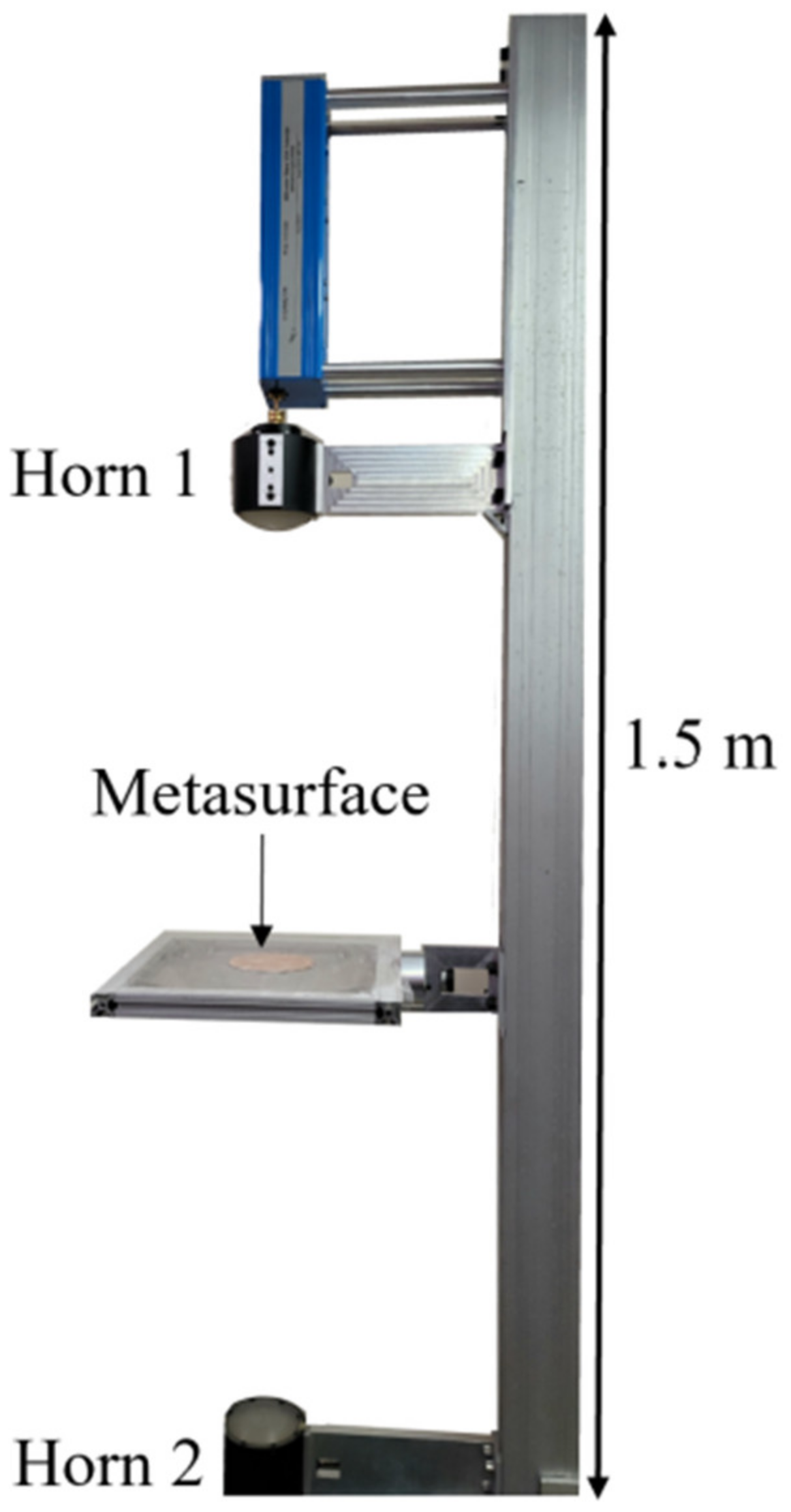
The transmittance spectra of the four powders acquired over the two experimental runs (conducted two weeks apart) were gathered using the apparatus shown in
Figure 10 and are presented in
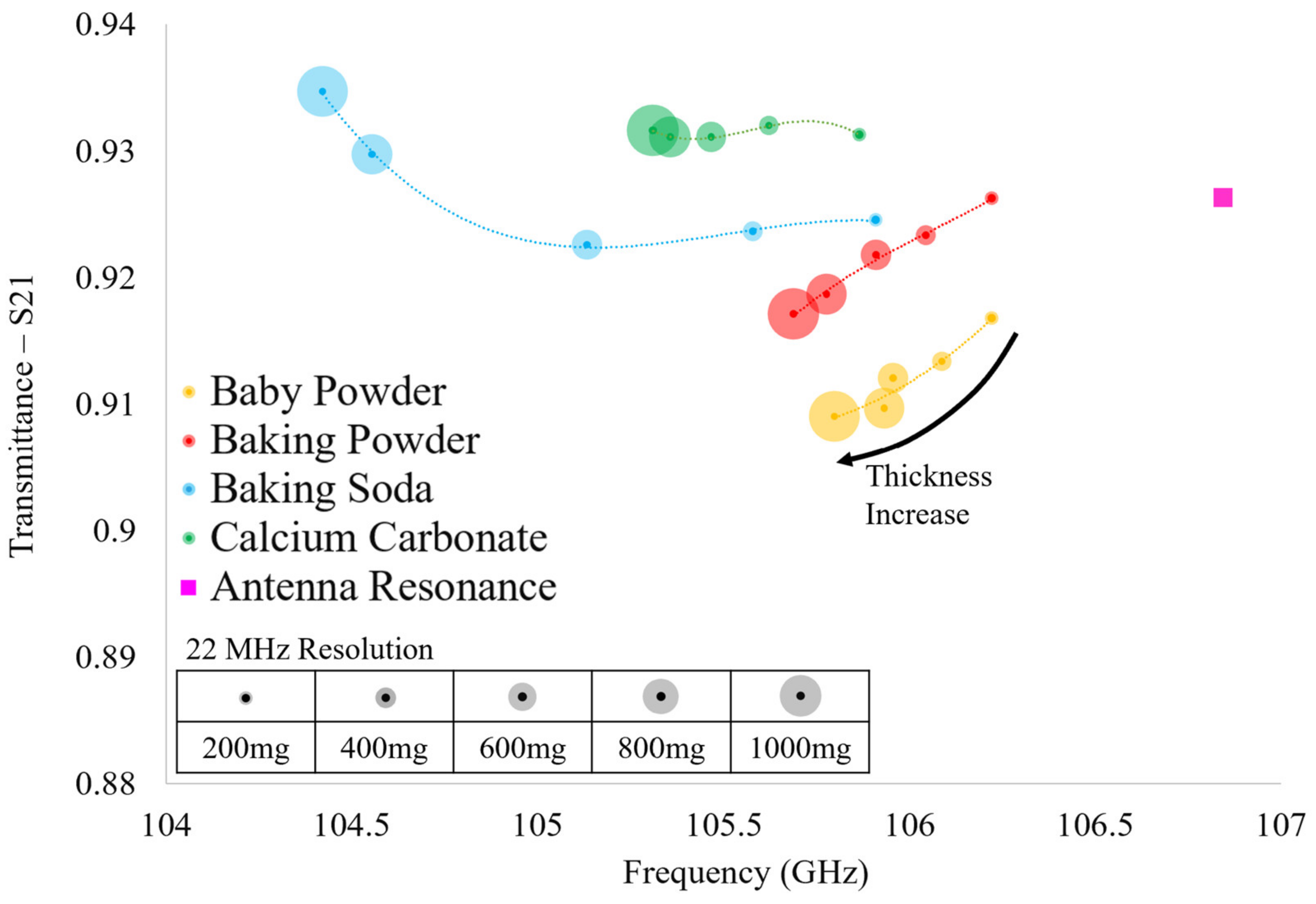
Figure 13. Looking at
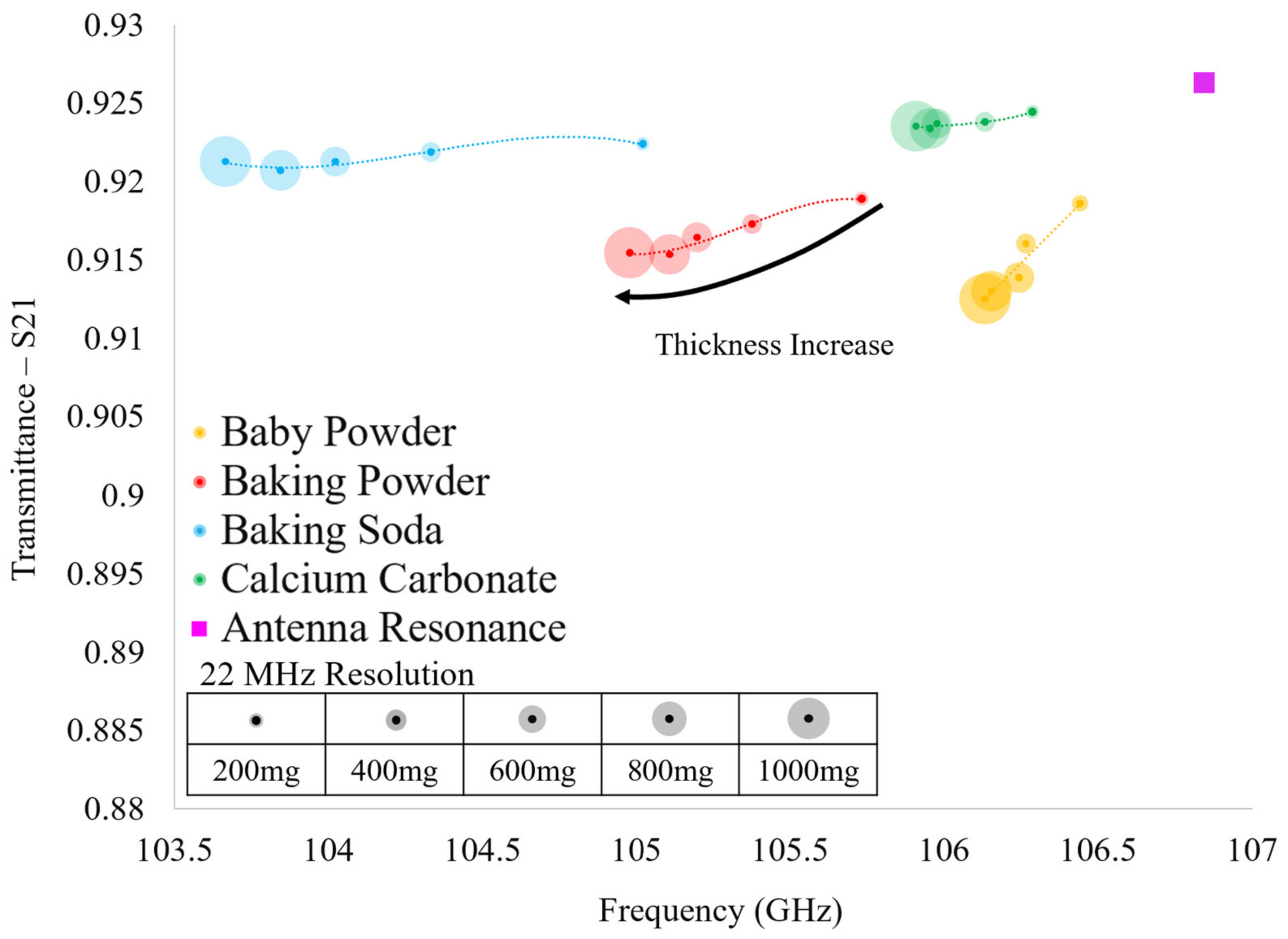
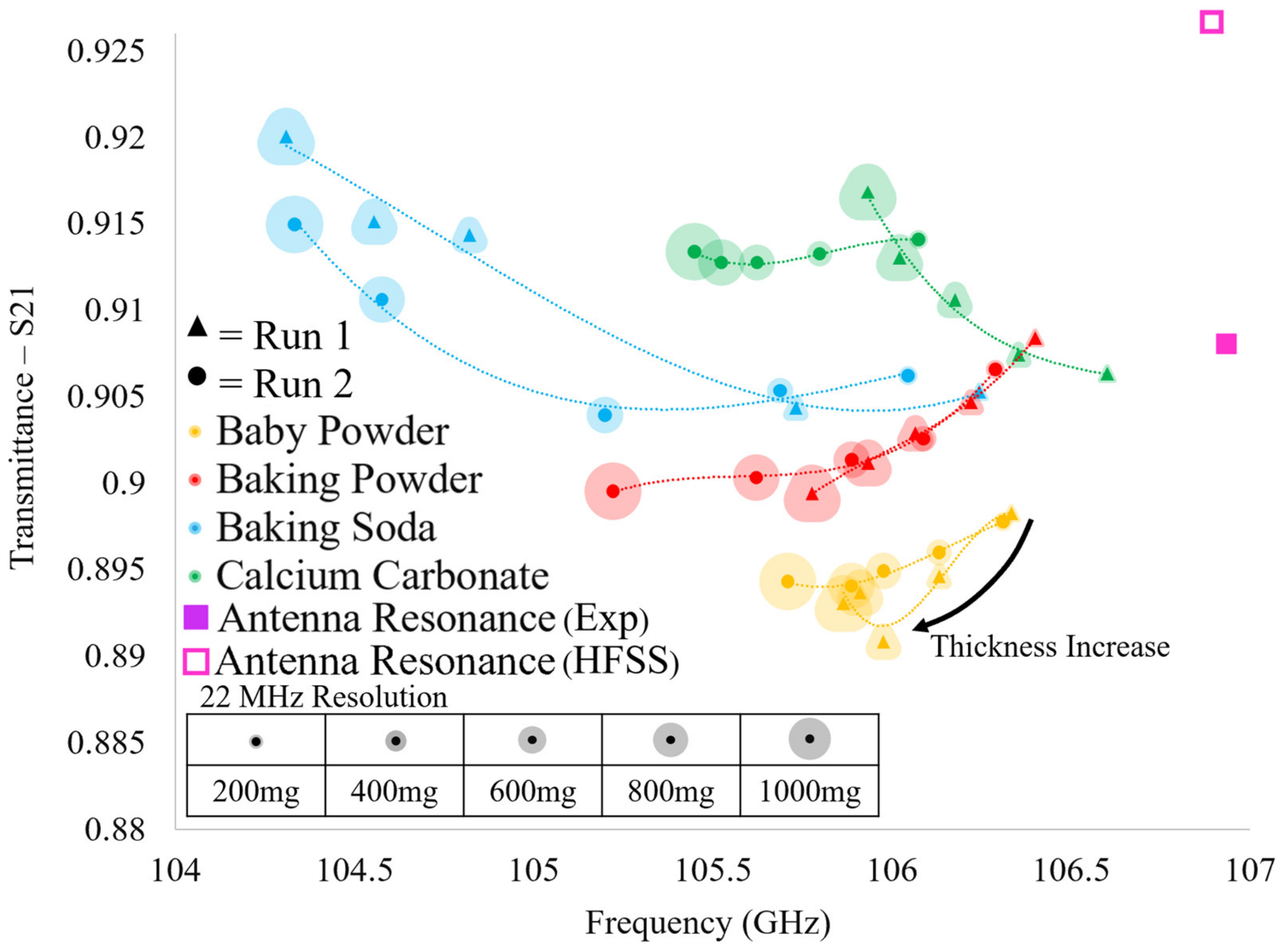
Figure 13, each point represents the maximum transmittance amplitude and the corresponding resonant frequency of each of the acquired transmittance spectra. It is clear that there are distinct differences in the evolution of the transmittance spectra between the four powders tested as a function of layer thickness. However, important similarities are observed between alike powders between successive runs, demonstrating the reproducibility and distinguishability of the proposed sensing technique. Furthermore, although we acknowledge that the relative shifts in transmittance amplitude between successive powder layers are relatively small, we suggest that this technique shows that the scale of the relative shifts in resonant values are not of great importance. We propose one must consider the resonant transmittance values of more than one powder layer on the metasurface before attempting to identify a particular powder. In so doing, one may consider each of the data points as an individual member of a distinct resonant spectral evolution belonging to a specific powder.
In this way, by viewing the evolution of the resonant transmittance values of a particular powder as a function of layer thickness, a distinct spectral signature may be produced. This spectral signature may allow one to identify a particular powder on the metasurface since, as seen in
Figure 13, no two powder species share even a similar spectral signature. Furthermore, we suggest that the spectral extremum of each powder could be acquired as a function of humidity in further experimentation, thus constraining the possible spectral evolutions for each powder. Doing so could produce a set of possible spectral signatures that may be observed using this sensing technique.
It is clear that there is a striking difference between the spectra simulated in HFSS using Maxwell Garnett effective medium theory (
Figure 12) and the experimental spectra (
Figure 13). However, they do agree with one another in that a decrease in relative resonant frequency shifts between successive powder layers is observed as the layer thickness increases (with the exception of baking soda). In further agreement with theory, the greatest relative shift in resonant frequency between adjacent resonant points of the same species is observed when increasing the layer thickness from 0 mg to 200 mg, as was observed in the experiments, indicating that the device is sensitive to minute changes in the ambient environment.
In comparing the two experimental runs, it is clear that there are similarities and differences between identical powders, but there are still unique characteristics belonging only to powders of the same species. For instance, calcium carbonate and baking soda both reliably produced transmittance spectra which rose above the bare antenna resonance values. However, spectra produced in HFSS using Maxwell Garnett effective medium theory and average effective thicknesses never produced a transmittance amplitude that surpassed the bare antenna peak. Furthermore, baking soda produced an interesting result in the experiments: in Run 1 there is a large jump in resonant frequency and transmittance amplitude from the 200 mg layer to the 400 mg layer and a similarly perplexing jump from the 600 mg layer to the 800 mg layer in Run 2 (diverging from the pattern observed in simulation and distinct from the other powders’ spectral evolution observed experimentally).
Since the two runs were carried out two weeks apart and the same anomalous transmittance responses were observed each time in baking soda and calcium carbonate (while baby powder and baking powder also remained consistent in their respective spectral evolutions between experimental runs), the anomalous responses may not be easily written off. These “jumps” and transmittance amplitudes which extend above the bare metasurface response may offer insights into some key physics taking place between the powders and the metasurface apertures (a possible explanation detailing the physical significance of these anomalous observations is offered in
Section 4).
Looking at
Table 3, the difference in total powder mass on the metasurface suggests that the spectral signatures of similar powders between experimental runs should not be identical, and indeed, they differ slightly from one another (save calcium carbonate). However, the discrepancies between simulation using Maxwell Garnett effective medium theory and the experimentally observed anomalous behavior of the thin powder layers are too great to ignore. These anomalies suggest that perhaps a new effective medium theory be realized in order to fully characterize the complex dielectric properties and effective thicknesses of thin dielectric powder layers.
3.2. An Equivalent Circuit Model of a Metasurface
This section serves as a detailed explanation of the techniques employed to produce an equivalent circuit model which reproduced the transmittance spectra acquired through simulation with a high degree of accuracy. It will be later shown in
Section 3.4 that by using the equivalent circuit model produced in this subsection to extract complex dielectric properties and effective layer thicknesses of the thin powder layers studied herein (to be used as parameters in HFSS simulations), better agreement between experimental and simulated spectra is obtained. In doing so, the physical properties of the powders were more clearly illuminated.
The series RLC circuit was the circuit upon which all transmittance spectra presented in this paper were described as each spectrum is singly resonant in nature [
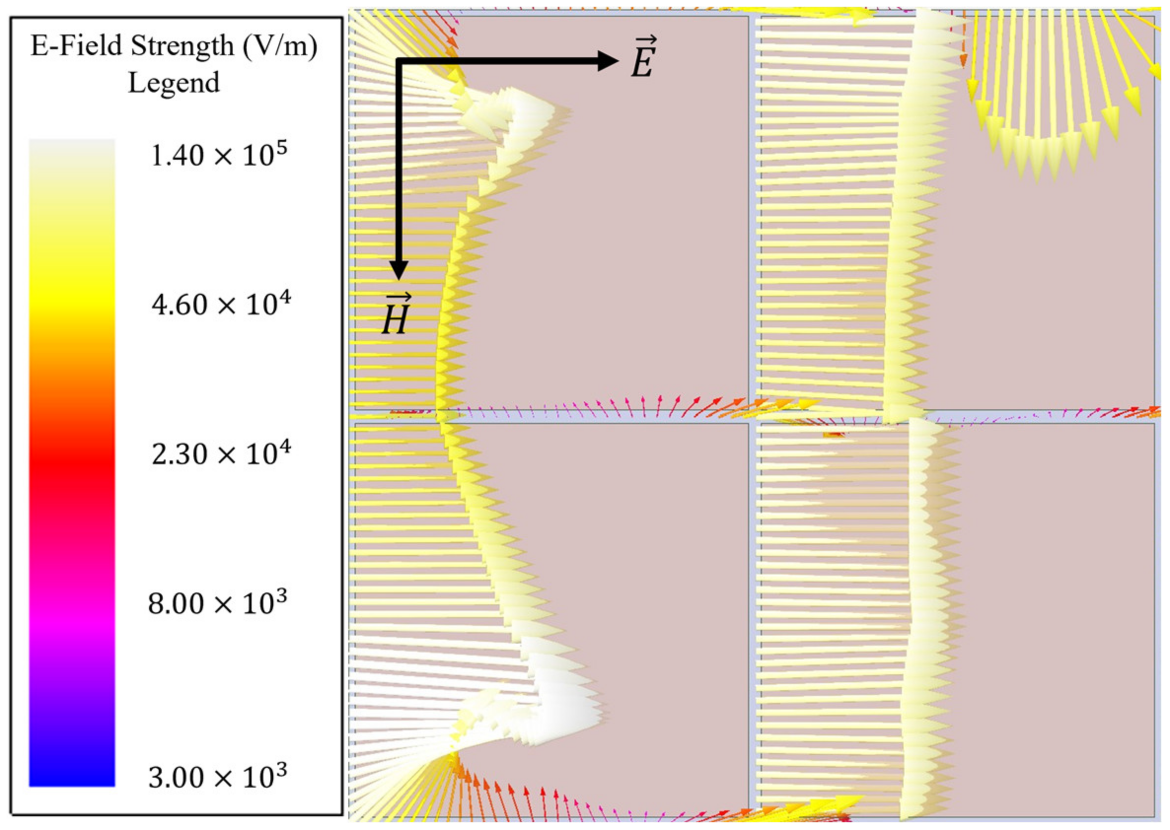
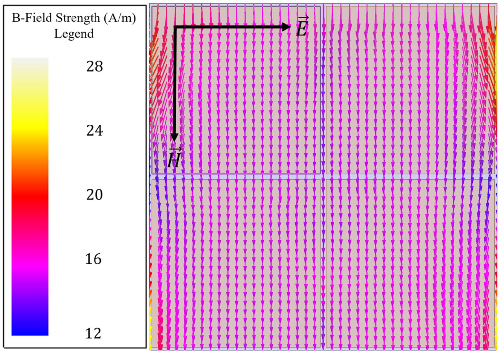
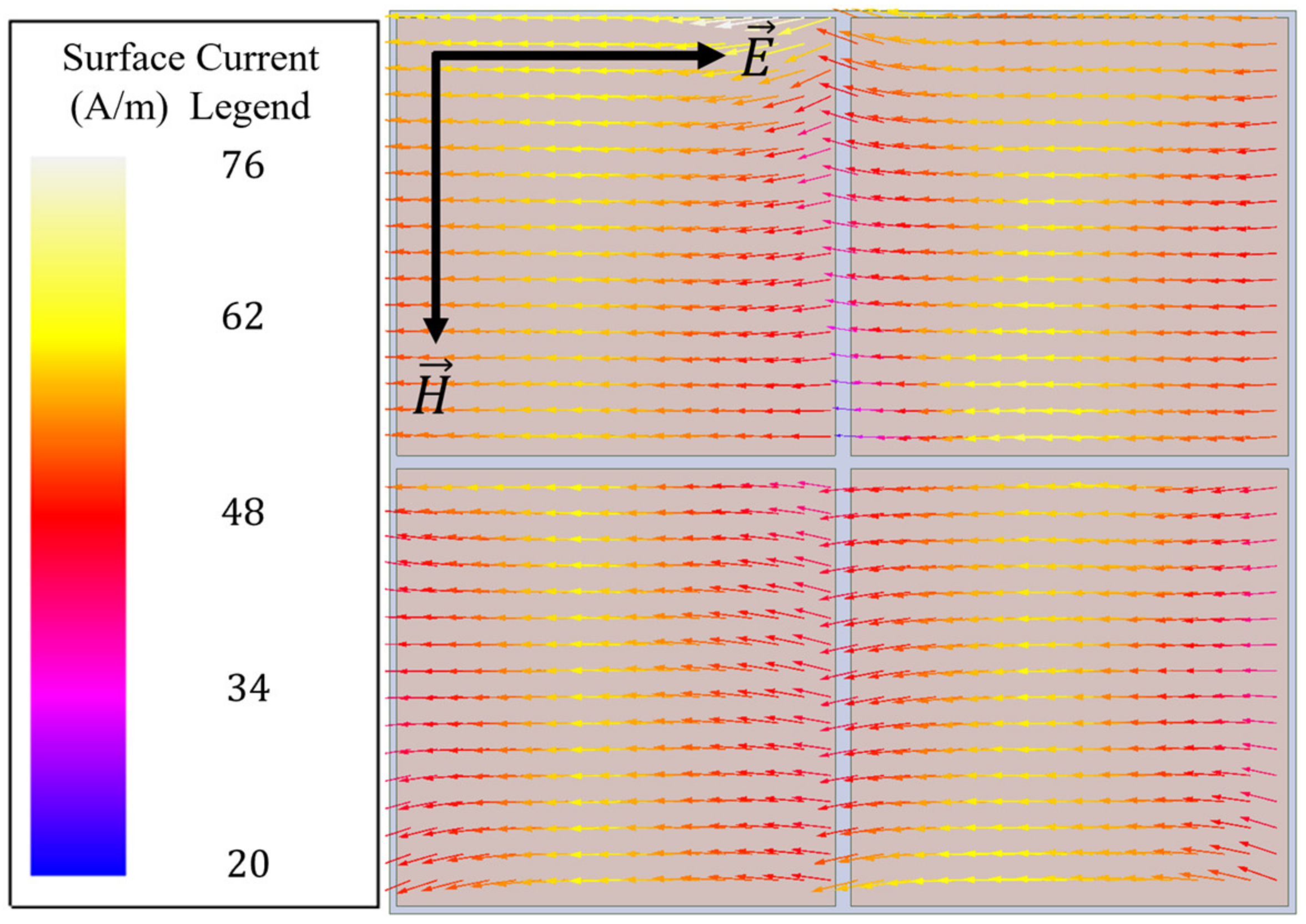
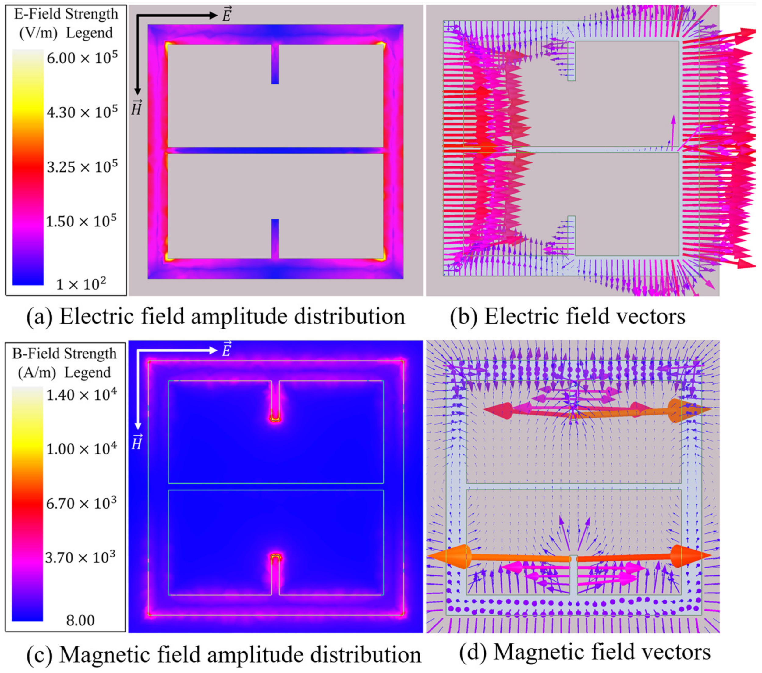
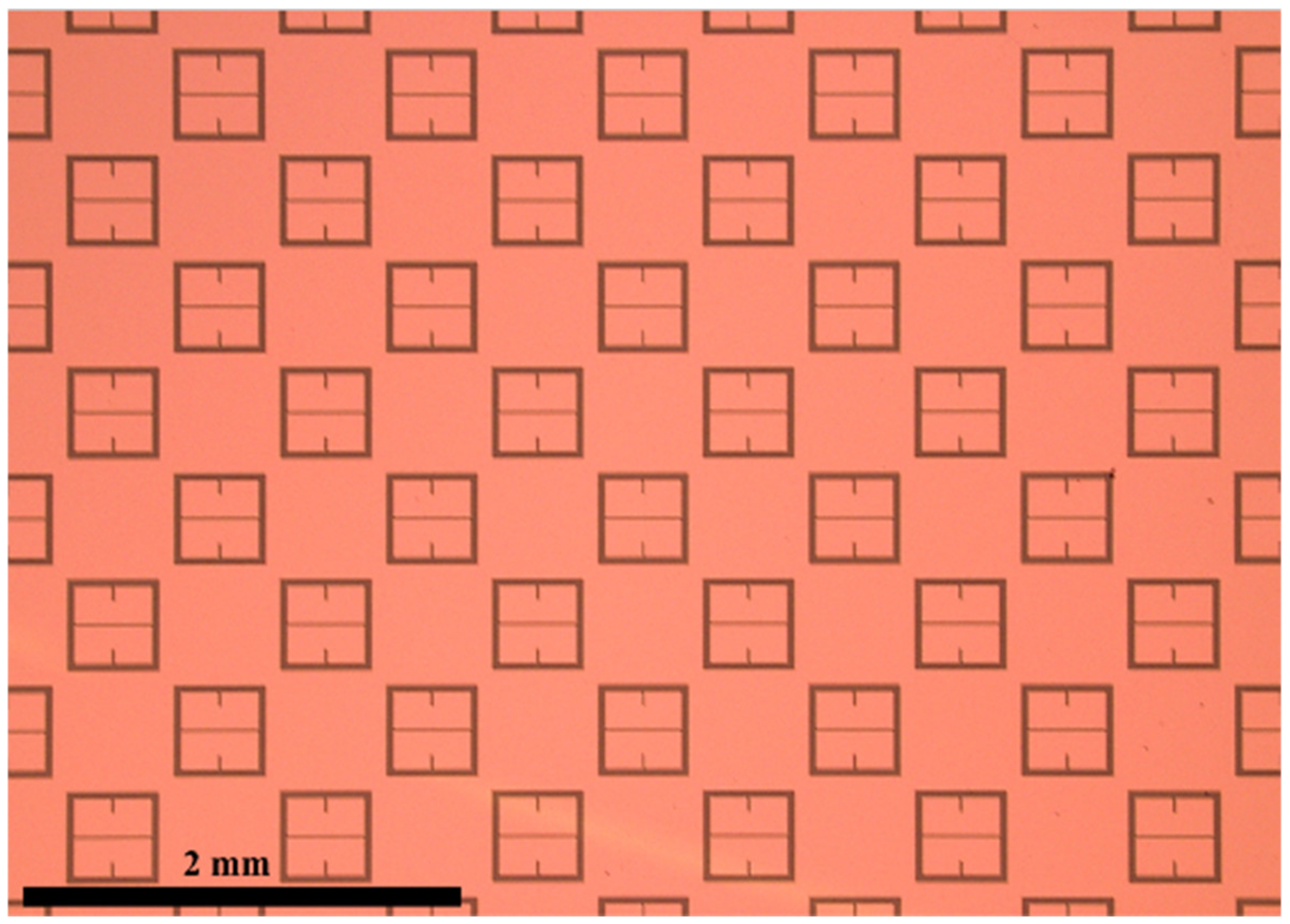
14]. For our metasurface topology, it was assumed that it behaves similar to a capacitive patch array as the electric field of the metasurface exhibits similar behavior between the gaps orthogonal to the incident electric field (as seen in
Figure 7a,b), and it is patch-like in shape. The following subsections detail the process by which the values of
R,
L, and
C were determined for the bare metasurface (to be used in the equivalent circuit method to determine powder properties).
3.2.1. The Capacitance (C) of the Metasurface
Since the metasurface is doubly periodic and, therefore, contains a non-trivial inter-patch spacing, the equation for the capacitor of the sought equivalent RLC circuit model was slightly modified from the classic form [
14] to account for the double periodicity and variable inter-patch spacing, the form of which is presented in Equation (4) [
24,
25].
In Equation (4), is the average distance between two active components within the unit cell, P is the lattice period, and are the effective permittivities of the substrate and the material directly above it, respectively, and is the permittivity of free space. The value of the capacitance of the RLC circuit is an essential parameter, for it is solely responsible for changing the position of the resonant peak of transmittance spectra between active circuit ports in frequency alone.
Finding the Average Inter-Patch Spacing ()
It was determined that the average inter-patch spacing between the two active components of the unit cell,
, could be easily found by utilizing Equation (5).
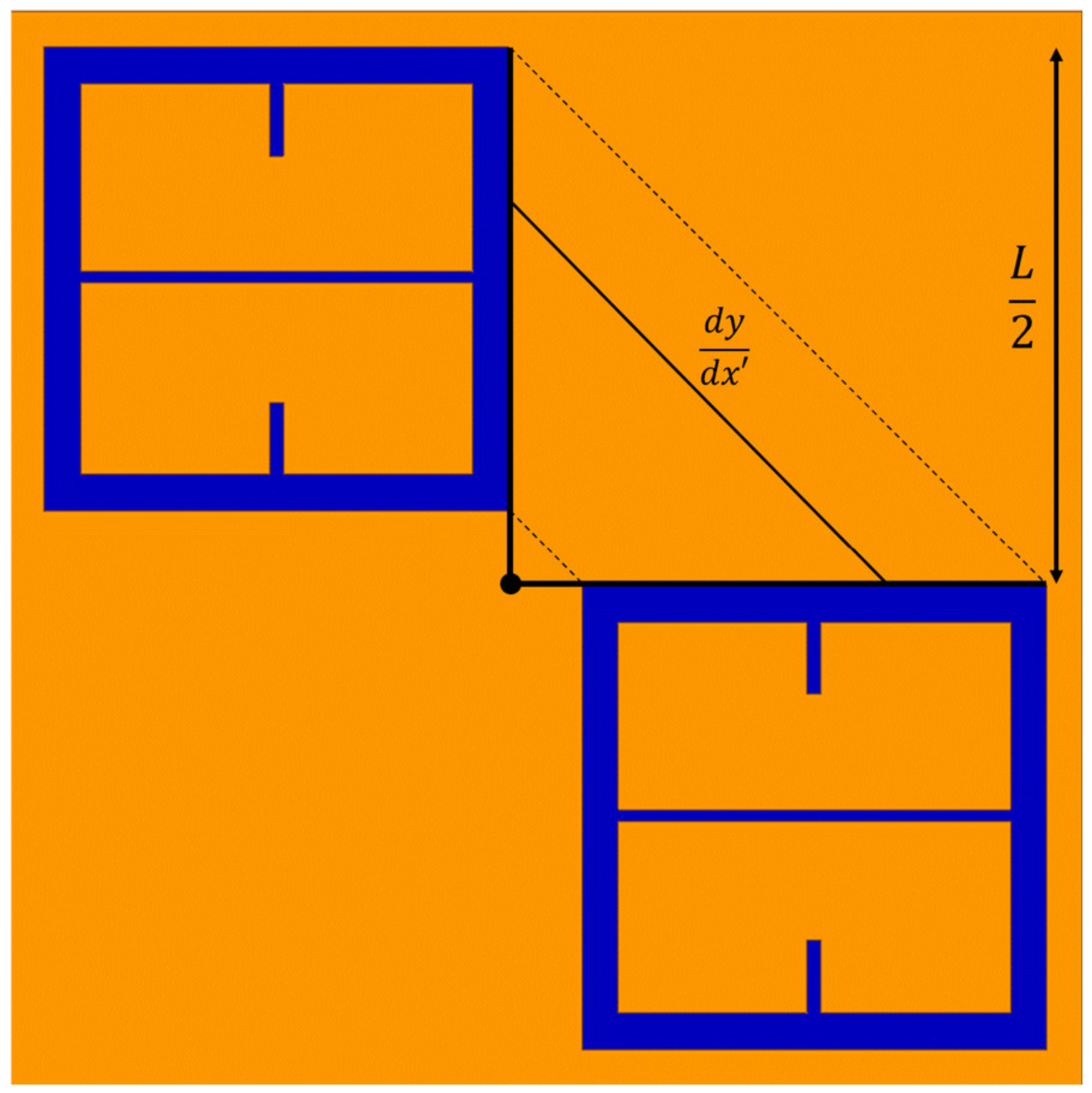
In Equation (5),
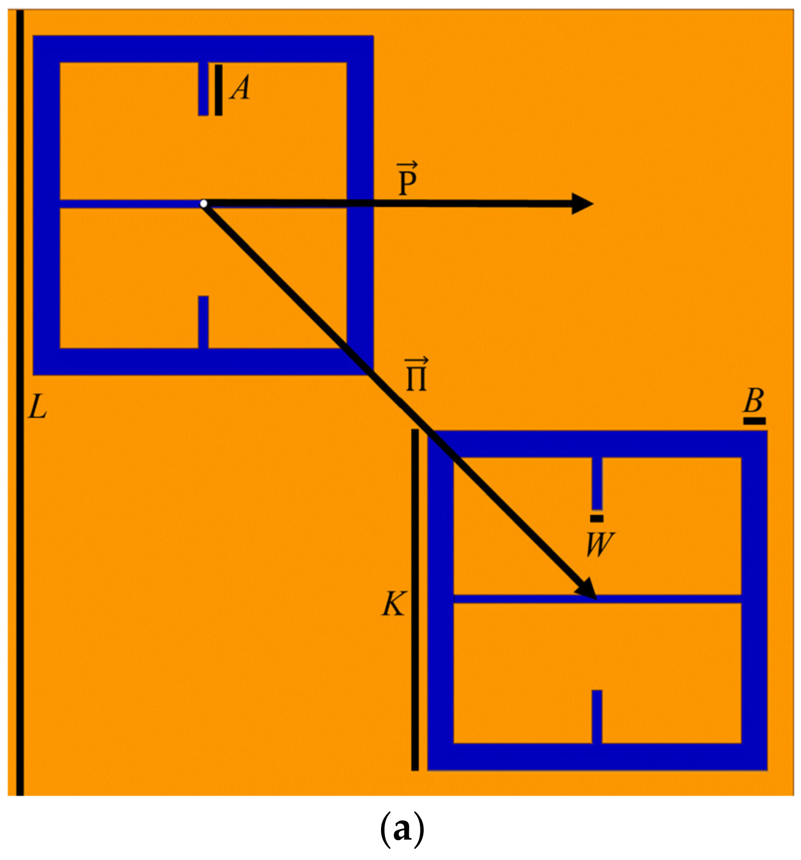
is the slope of the solid black line labeled
in
Figure 14. Since
= 1, after integration of Equation (5), it is found that
=
, where
L is depicted in
Figure 1.
Solving for the Capacitance (C)
In the case of the bare metasurface, in Equation (4), , and it was found that and . Thus, solving Equation (4), it was found that C = 1.64 fF.
3.2.2. The Inductance (L) of the Metasurface
Since at resonance the circuit impedance becomes purely resistive, one can derive an expression for the inductor as a function of the resonant frequency and the value of a capacitor [
31]. This equation is presented as Equation (8).
In Equation (8),
is
times the resonant frequency of the bare metasurface
, and
C = 1.64 fF. This produces an inductor value of
, which is held constant in all the following circuit simulations presented in this study (why this is so is explained later in
Section 3.2.4).
3.2.3. The Resistance (R) of the Metasurface
Since the metasurface simulated in HFSS is not perfectly transmissive at resonance, a resistor was placed in series with the inductor and capacitor to accurately model the resonant response of the metasurface. The resistor lowers the amplitude at which resonance occurs and does not affect the resonant frequency. Similarly, holding the value of the inductor constant in this study, the capacitor explicitly controls the position of the resonant frequency.
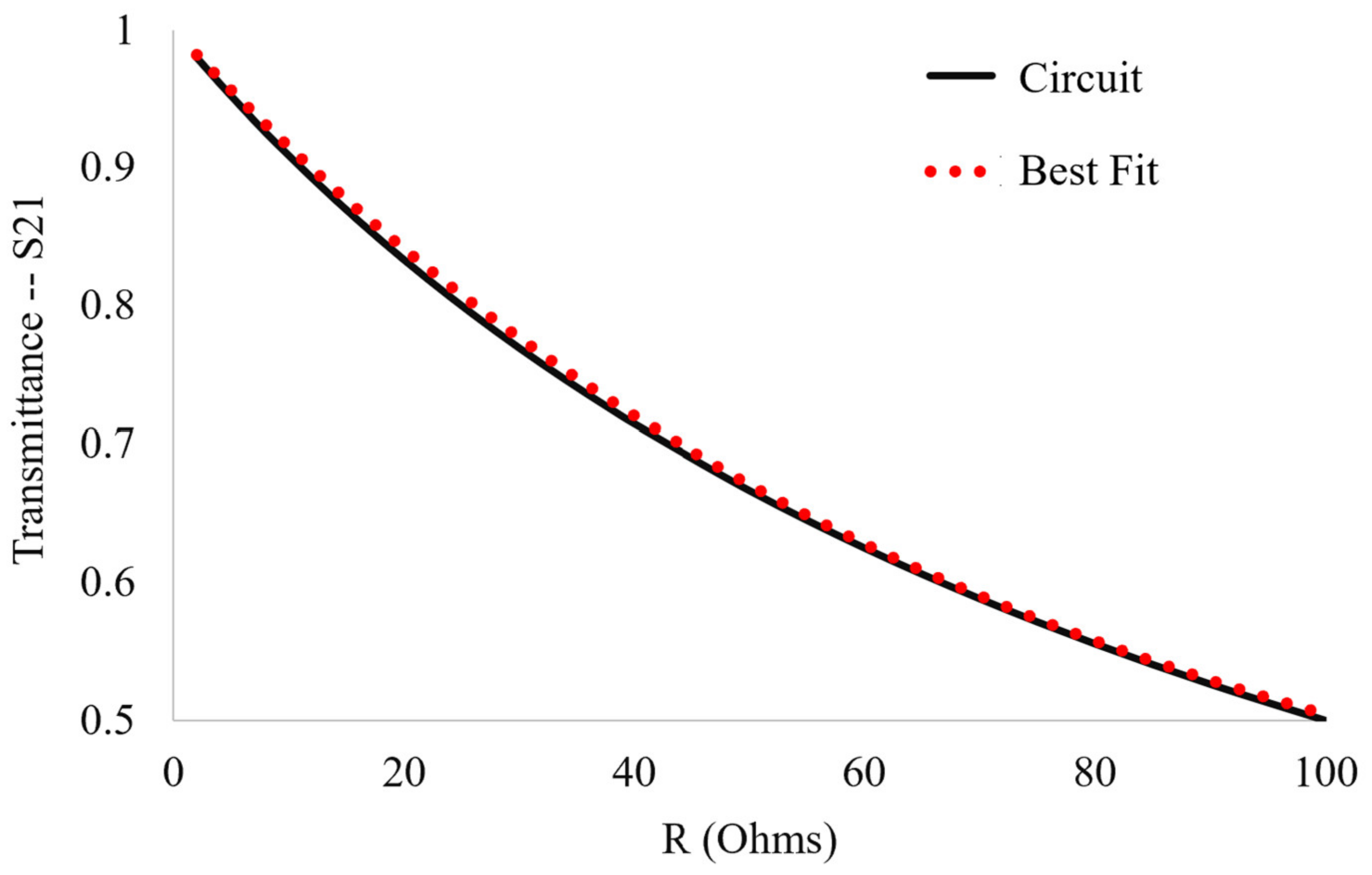
To find
R, the resonant response of the fundamental circuit (the circuit with the constant capacitance and inductance of the bare metasurface) as a function of the resistor value was modeled by utilizing the fact that the envelope of the energy dissipation rate in a series RLC circuit falls off in a manner proportional to
. Upon probing the transmittance response of the equivalent circuit model in QUCS (a circuit simulation software) to changes in
R, the best fit very closely matches:
where
L is the equivalent circuit value of the inductor (the metasurface inductance, 1.35 nH), a constant throughout this paper, and
, which is the inverse of the resonant frequency of the bare metasurface. Equation (9) allows one to estimate a value for
R given any maximum transmittance amplitude through the metasurface–powder interactions. The graph and best fit of the transmittance vs. resistor value for the fundamental circuit, given by Equation (9), is presented in
Figure 16.
Fitting the response of the fundamental circuit to changes in resistor value to Equation (9) produces a good agreement, within 0.5%. The correct series resistor value was determined to be R = 7.92 Ω for the bare metasurface transmittance amplitude as simulated in HFSS.
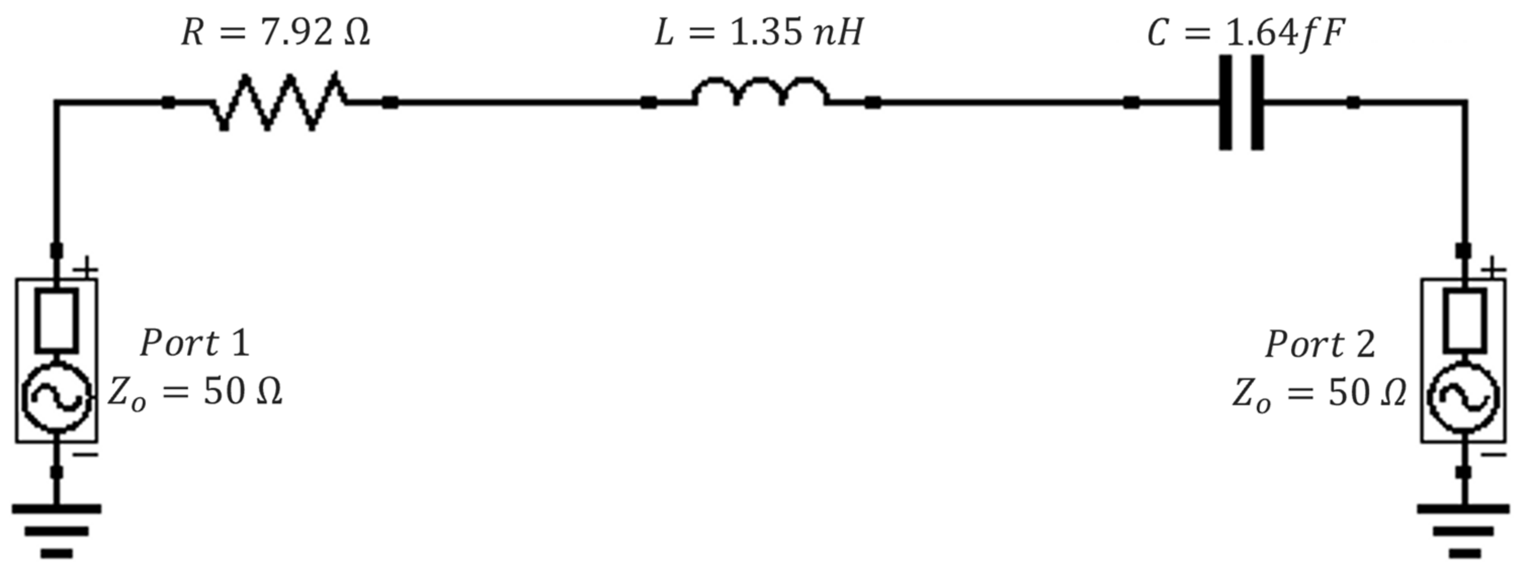
3.2.4. The Resulting Equivalent Circuit Model for the Bare Metasurface
Since
R,
L and
C for the bare metasurface are known values, the equivalent circuit for the metasurface is presented in
Figure 17. It was found that one could change the position of the resonant peak of the transmittance spectra of the equivalent circuit by changing the value of the capacitance and resistance and holding the inductance constant. This fact will prove advantageous in determining effective dielectric constants and layer thicknesses of powders, whose methodology is be presented in
Section 3.3.
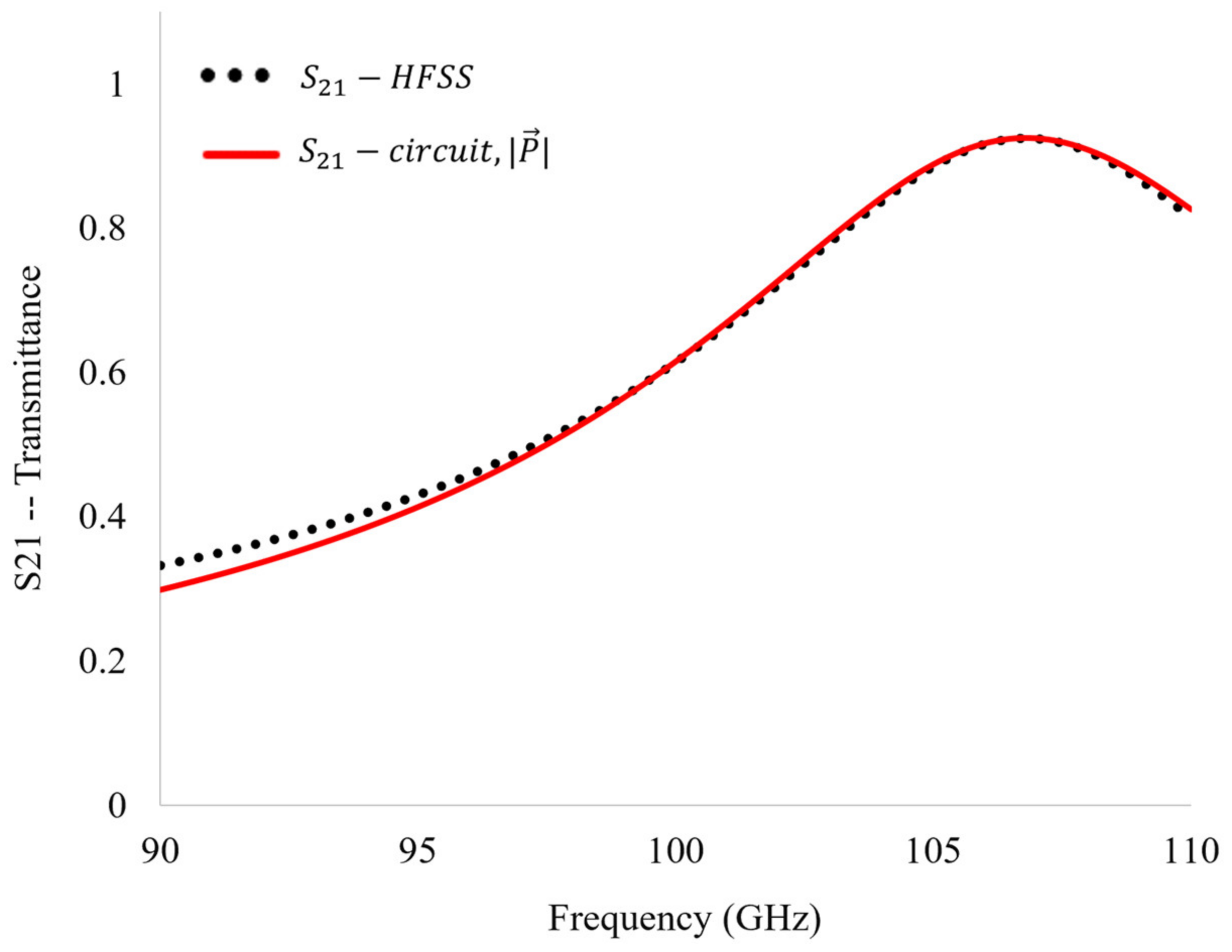
The transmittance spectra of the circuit were simulated using QUCS. It was shown that the equivalent circuit with the values of
R,
L, and
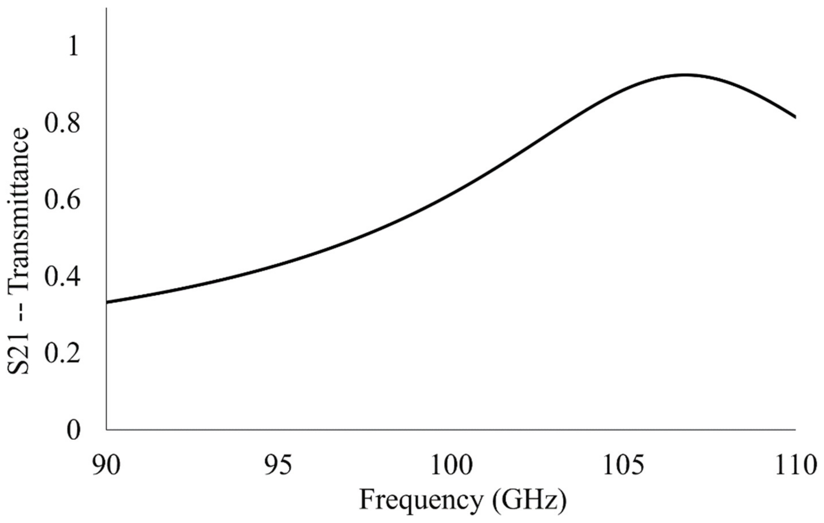
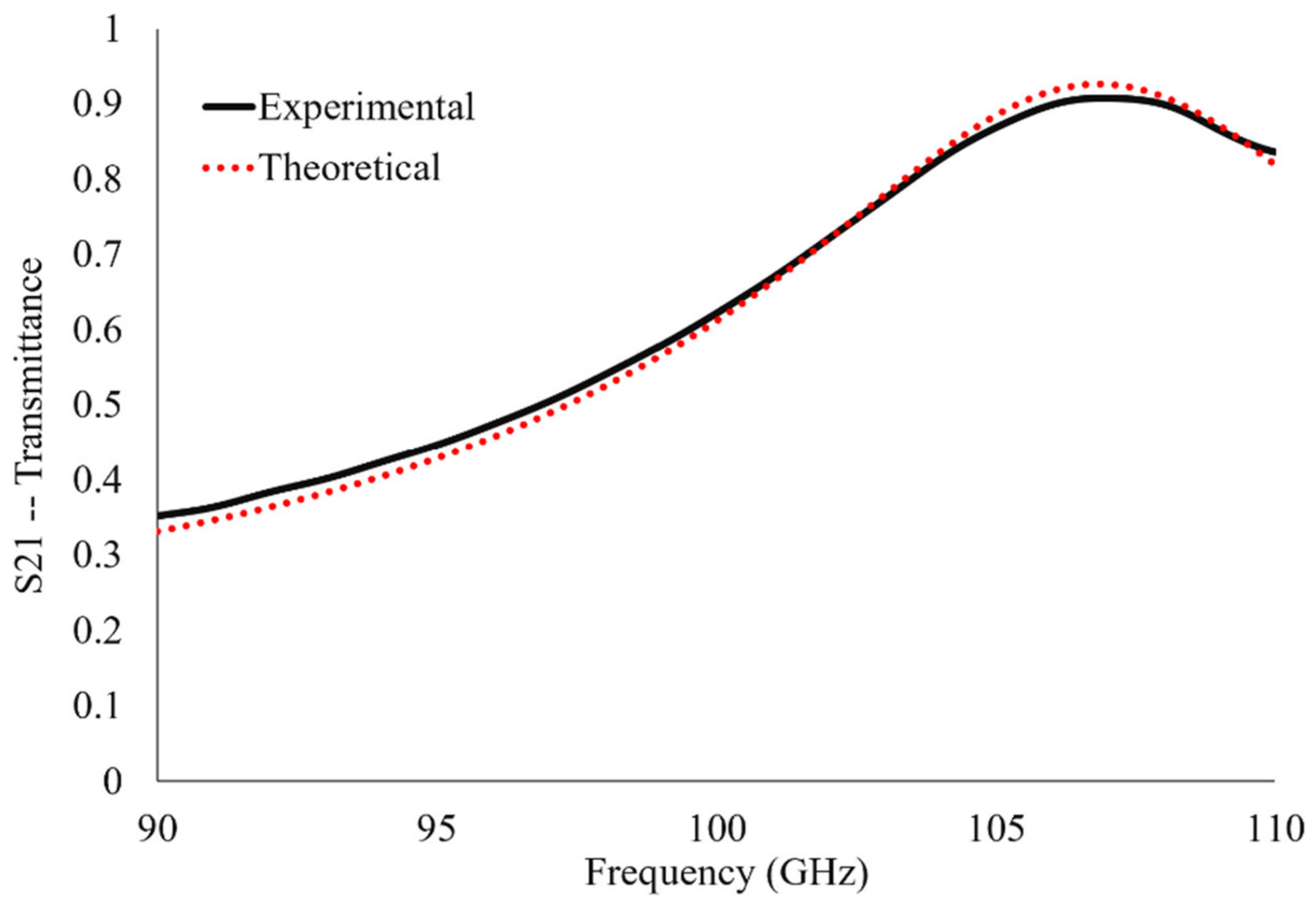
C derived in the previous subsections produces a unique solution which matches the bare metasurface’s transmittance spectrum obtained in HFSS (
Figure 18). It was found that there was a 0.95% difference between the transmittance spectra produced in QUCS and those obtained through metasurface simulation in HFSS. This agreement confirms that our metasurface was justly treated as a modified capacitive patch array.
3.3. Effective Complex Dielectric Properties and Thicknesses of Thin Inhomogeneous Dielectric Powder Layers Extracted from an Equivalent Circuit Model of a Metasurface
It was previously shown that poor agreement between the experimental (
Figure 13) and simulated (
Figure 12) transmittance spectra of thin inhomogeneous powder layers was produced using average effective thicknesses and Maxwell Garnett effective medium theory (whose values were derived using the methods described in
Section 2.5). We propose that if one could find a set of complex dielectric constants and powder layer thicknesses which (when simulated in HFSS) produce relative shifts in resonant frequency and transmittance amplitude for each powder layer observed experimentally, that the powder layers could be effectively characterized. After the dielectric properties of each powder layer were extracted using the equivalent circuit approach (and each effective powder layer thickness approximated), simulations of the metasurface with powder layers on it (which carry the equivalent circuit derived effective complex dielectric properties and layer thicknesses) were conducted in HFSS. The resulting simulated resonant spectra were then compared to those obtained via experimentation. The exact method employed to perform this study is detailed directly below.
Since an equivalent circuit model was obtained (
Section 3.2.4) which describes the bare metasurface transmittance spectra to within 1% (sharing the same maximum transmittance amplitude and resonant frequency), it was suggested that it could be used to extract the effective complex dielectric properties and layer thicknesses of each inhomogeneous powder layer tested. This is possible in part because the value of the capacitor in the equivalent circuit (see Equation (4)) is determined solely by the permittivity of the material in contact with the metasurface,
(where all the other parameters in Equation (4) are static, physical features of the metasurface structure).
As a note, since each powder layer has a unique layer thickness and set of complex dielectric constants produced using this technique, for sake of brevity, only Run 2 experimental data will be characterized and presented in this paper (whose resonant spectra are presented in
Figure 13).
Though the differences in resonant frequency and transmittance maxima between the two curves in
Figure 11 appear to be small, they are significant on the scale of the experimentally measured data (see
Figure 13, solid and hollow square data points). In order for the equivalent circuit model to extract accurate complex dielectric constant and effective thickness values suitable for predicting experimental spectra, the differences between measured and simulated resonant frequency and transmittance maxima were compensated for. Consequently, the relative shifts in transmittance amplitude and resonant frequency were used to compare the simulated and experimentally acquired transmittance spectra. Therefore, if a powder produced a resonant frequency and maximum transmittance amplitude in the experiment which departed from the bare antenna resonance values by
(%) and
(%), respectively, the resonant frequency used in the acquisition of effective dielectric constants and thickness values using the equivalent circuit technique was:
and similarly for transmittance:
where
and
are the transmittance amplitude and resonant frequency of the bare antenna, respectively, as simulated in HFSS. Values of
and
for each powder layer are presented in
Table 8. Since the value of the inductor is held constant (1.35 nH) in this study, one can plug in the shifted resonant frequency values (found after solving Equation (10) for each powder layer) into Equation (8), and the effective value of the capacitor, C, can be found for each powder layer. Then, by plugging
C into Equation (4), one can solve for
, where all other parameters are known. The values of the real component of the effective permittivity,
, of each powder layer found using the relative frequency shifts are presented in
Table 8 (labeled as
.
By holding constant two of the three parameters necessary to perform a simulation in HFSS (the thickness and the real component of the complex permittivity), the response of the metasurface to changes in the value of dielectric loss tangent for powders could be studied. The thickness for each powder species was kept constant at the median thickness value of the five powder layers previously estimated using the average effective thickness method, which are presented in
Table 5. The median thickness of each of the species, therefore, was three times the individual average effective thicknesses in
Table 5 (since in total five layers were applied). The real component of the permittivity of each of the clads were also held constant at the median value extracted by use of the equivalent circuit model, presented in
Table 8, for each powder species. Justification for this procedure follows below.
This treatment assumed that the transmittance amplitudes of the spectra should remain relatively stable upon changes to the thickness or real component of the permittivity, which was later confirmed. Upon parametric fitting of the response of the metasurface-powder transmittance spectra to changes in the loss tangent of a powder, a unique equation for each powder as a function of loss tangent was obtained. This allows one to estimate the loss tangent of each powder layer as a function of transmittance amplitude using the equation:
In Equation (12), α can take the values of 1 or 4 for each powder, and is the exponential component which characterizes the energy dissipation of the RLC circuit. is the minimum resistor value predicted via Equation (9) for each powder (the minimum resistor value was chosen arbitrarily since fit parameters may account for changes). is the transmittance amplitude of the metasurface as predicted in HFSS with no powder on the surface, is the loss tangent of the pressed powder whose effective values were extracted using a Fresnel fitting procedure and Maxwell Garnett theory, and and γ are constant factors which are found using a parametric fitting procedure.
The justification for using as an estimate in Equation (12) lies in the fact that the volumetric density and fill factor of the powders (which are directly determined by their densities) as they sat on the metasurface (after it was attempted to apply 1000 mg) were known with greatest certainty. Equation (12) allows one to plug in a relative transmittance value,, into the left-hand side, and the appropriate parameters into the right-hand side; then, using a computational solver of choice, a value for the loss tangent of the powder layer which produces the input relative transmittance amplitude was obtained.
It was determined that even though two of the three parameters necessary to perform a simulation in HFSS were held constant, a much better agreement in transmittance spectra between experiment and simulation was observed in comparison with simulations using Maxwell Garnett effective medium theory and the average effective thickness treatment of each powder layer (still, we felt it could be improved upon even further by extracting effective layer thicknesses with the aid of the equivalent circuit model). The final values of the loss tangent for each powder layer are presented in
Table 8 as
. A possible explanation of the significance of the negative values of
is offered in
Section 4.
Finally, to further increase the agreement between experiment and theory, more accurate effective thicknesses of each powder layer were determined. For each 200 mg layer of powder that was attempted to be deposited onto the metasurface, the percent divergence from the resonant frequencies of the bare antenna resonance (in experiment and HFSS) versus the mass of each powder layer were parametrically fit using a third order polynomial of the form:
where
are the parameters of best fit and
is the layer-mass in milligrams. It was found that the adjusted effective thickness (
) of each powder layer could be estimated using Equation (14).
In Equation (14),
is the equation of best fit for the experimental relative frequency shifts,
is the equation of best fit for the the relative frequency shifts obtained using the equivalent circuit method previously described, and
is the median thickness used to simulate each powder while probing the resonant response of the metasurface as a function of loss tangent. The success in utilizing the adjusted effective thickness values with equivalent circuit derived dielectric properties is presented in the next subsection. The improved estimates of effective thicknesses
of each powder layer are presented in
Table 8.
3.4. Simulated Transmittance Spectra of Thin Inhomogeneous Dielectric Powder Layers Using Equivalent Circuit Derived Parameters
We sought an effective medium theory whose dielectric constants and layer thicknesses might produce simulated transmittance spectra (in HFSS) that more accurately represent those observed in experiments (and therefore physically characterize the powder layers) in a way the Maxwell Garnett effective medium theory could not. Such an ability could aid in the identification of powders present on a metasurface. We elected to use an equivalent circuit model to extract the complex dielectric properties and effective layer thicknesses of each powder layer experimentally tested (whose values were found using the methodology of
Section 3.3). The spectra produced in HFSS using the three essential components estimated using the equivalent circuit method (
,
and
, whose values are presented
Table 8) are presented in
Figure 19.
As can be seen in
Figure 19, the spectral signatures simulated in HFSS (using equivalent circuit derived complex dielectric properties and layer thicknesses) have forms much more familiar than those produced in HFSS using Maxwell Garnett derived complex dielectric constants. This becomes increasingly evident when one directly compares the spectral signatures of Run 2 data (
Figure 13) with those presented in
Figure 19. However, because of the difference in experimental bare metasurface resonance values and those produced in simulation (see the difference between solid and hollow squares in
Figure 12), the “shape” of each spectral signature alone is not sufficient to make a true comparison. Therefore, we offer the relative shifts in frequency and transmittance amplitude from the bare metasurface simulated using the equivalent circuit method derived complex dielectric constants and thicknesses (HFSS) to be compared with the experimentally acquired transmittance spectra and those simulated using the Maxwell Garnett effective medium theory derived complex dielectric constants (HFSS). The relative shifts in resonant frequency and transmittance amplitude induced by the presence of a powder layer (the relative shifts in maximum transmittance amplitude and resonant frequency from the bare metasurface resonance values found in experiment and simulation) are presented in
Figure 20 and
Figure 21, respectively.
In
Figure 20 and
Figure 21, there is a marked improvement in agreement between the relative frequency and transmittance amplitude shifts measured in the experiments (in black), those determined using circuit derived complex dielectric constants (in red) and the values of effective thicknesses over Maxwell Garnett effective medium theory (in blue). This is true for all examples presented herein, except for the relative shifts in transmittance amplitude for the 800 mg and 1000 mg baby powder layers (
Figure 21a).
It was determined that it is possible to describe the anomalous transmittance enhancement above the bare antenna transmittance value as an effective medium with known thicknesses and possessing negative imaginary components of the effective permittivity. This suggests that there may be some enhancement mechanism which is not accounted for using the Maxwell Garnett effective medium theory (as it was observed in both experimental runs). A possible explanation for this enhancement is provided in
Section 4). However, because the proposed equivalent circuit method with which the effective thicknesses were extracted and the complex dielectric constant values derived utilizes equations of best fit for the loss tangent, it is clear that a complete theory needs to be realized.


