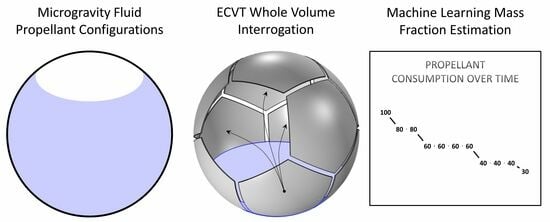
An ECVT sensor consists of a tessellation of metal electrode plates around the surface of a region of interest (RoI).
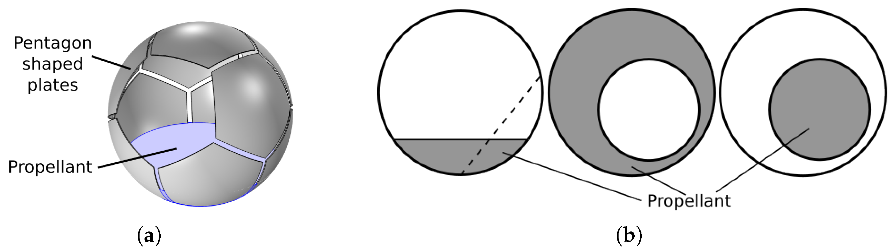
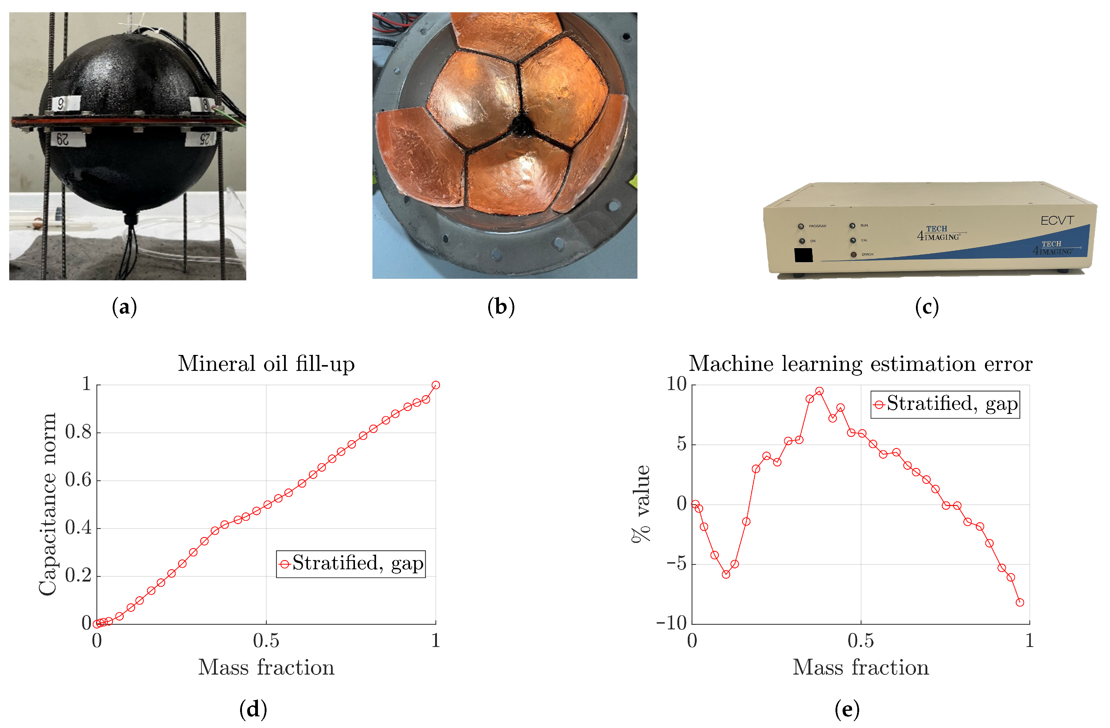
Figure 1a shows the sensor used here, which is of spherical shape with pentagonal plates, similar to a soccer ball. This mimics the spherical fuel tanks usually used in spacecrafts. The sensor consists of 12 equal-sized plates, a geometry called a spherical dodecahedron. The intersection region among three adjacent plates is referred to as a ‘gap’ here. There are 20 gaps for the present case. The plates are connected to a data acquisition device, which excites the plates in a sequential order and records the mutual capacitance among all possible plate pairs. The total number of measurements for an
n-plate sensor is therefore provided as
, which is 66 for the present 12-plate sensor. The mutual capacitance between two plates
is defined as
where
denotes the measured current at plate
i,
denotes the applied voltage at plate
j, and
denotes the angular frequency of the excitation signal. The rest of the plates are grounded during this process. A plate pair is often referred to as a ‘channel’. Each channel is normalized with respect to empty and full capacitance data as
Here,
and
refer to the capacitance data when the sensor is filled with the low- and high-permittivity materials, respectively, which are the air,
, and the propellant,
, for the present case. A partially filled fuel tank acts as a two-phase flow medium. The two-phase capacitance data,
C, contain information regarding the mass distribution in the RoI, from which the total mass fraction can be estimated through an appropriate inversion algorithm. It should be noted that two-plate sensors have been deployed for mass fraction estimation [
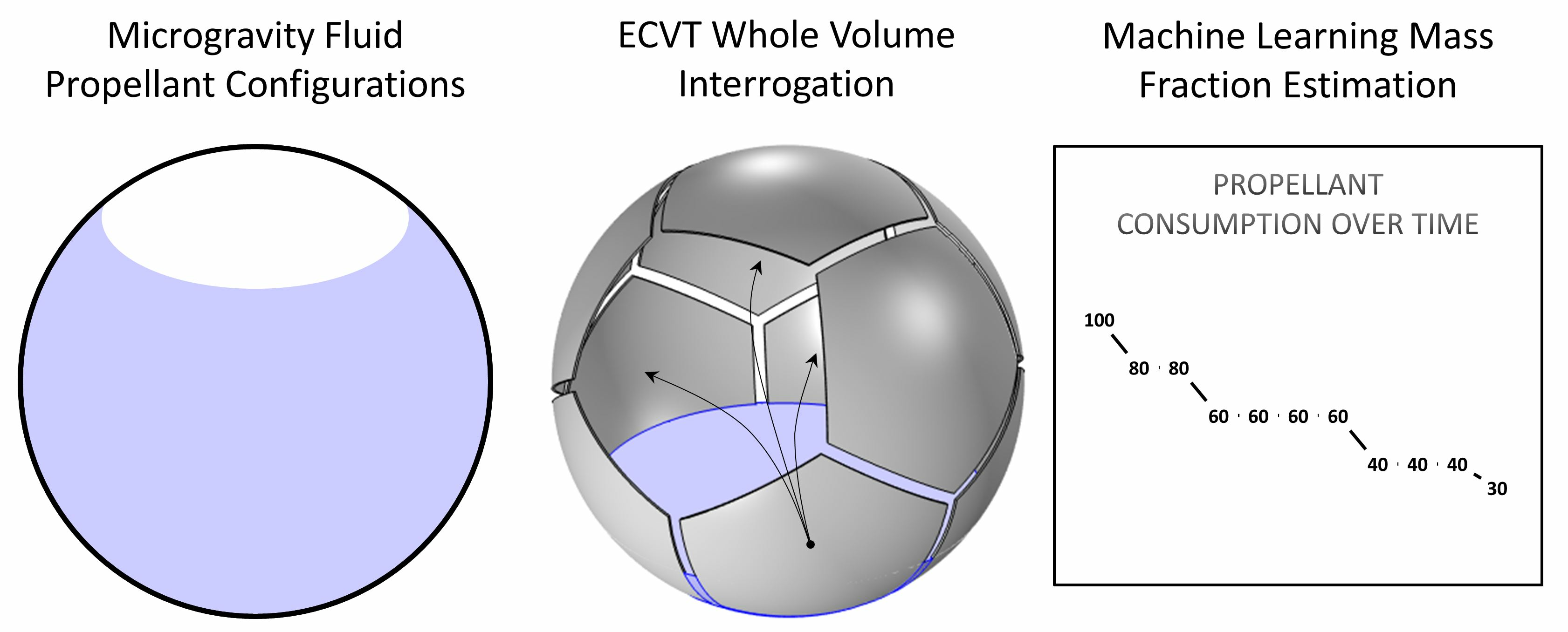
18]; however, they are suitable for rotationally stable flow regimes only. In micro-gravity conditions, the fluid configuration changes significantly, as illustrated in
Figure 1b, resulting in signal changes as a result of fluid position changes at constant fluid mass. An algorithm relying on only two plates or one data channel would inevitably misinterpret this as changes in mass fraction, producing erroneous results. This would become worse if the fuel mass is close to the gap between the plates, the region with the highest sensitivity. With additional plates, additional information is available for an algorithm to determine if changes in signal are due to changes in fluid mass or fluid position, or both, producing more accurate estimations. Also, a higher number of plates offer imaging capabilities in addition to mass fraction estimation, which provides complete information of the RoI. Moreover, it is possible to synthesize a two-plate sensor out of
n plates by electronically connecting the physical plates [
19]. The dodecahedron geometry shown in
Figure 1a is less sensitive to fluid position changes as compared to an octahedron, as reported in [
20]. This particular design has a high degree of rotational symmetry and a good balance between electrode surface area and number of electrodes, which helps in maximizing signal-to-noise ratio (SNR) and minimizing the positional sensitivity of capacitance data, thus improving estimation accuracy. This optimization performed at the sensor design stage has reduced many complications at the data inversion step that may have occurred otherwise.
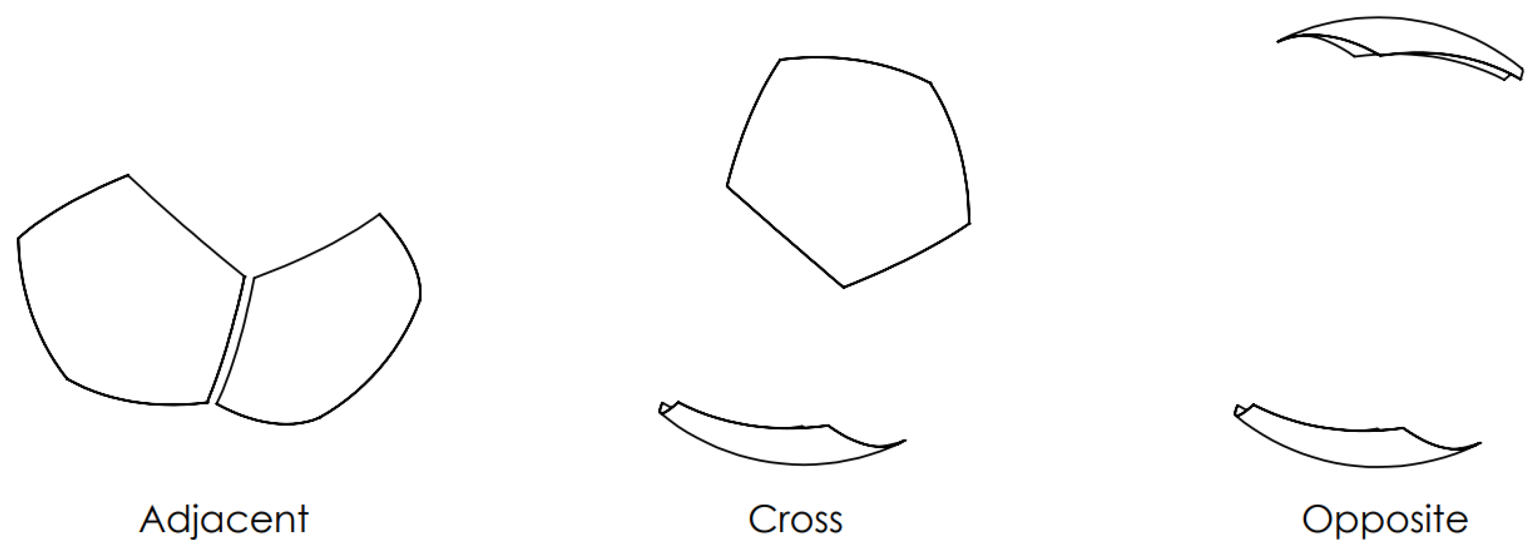
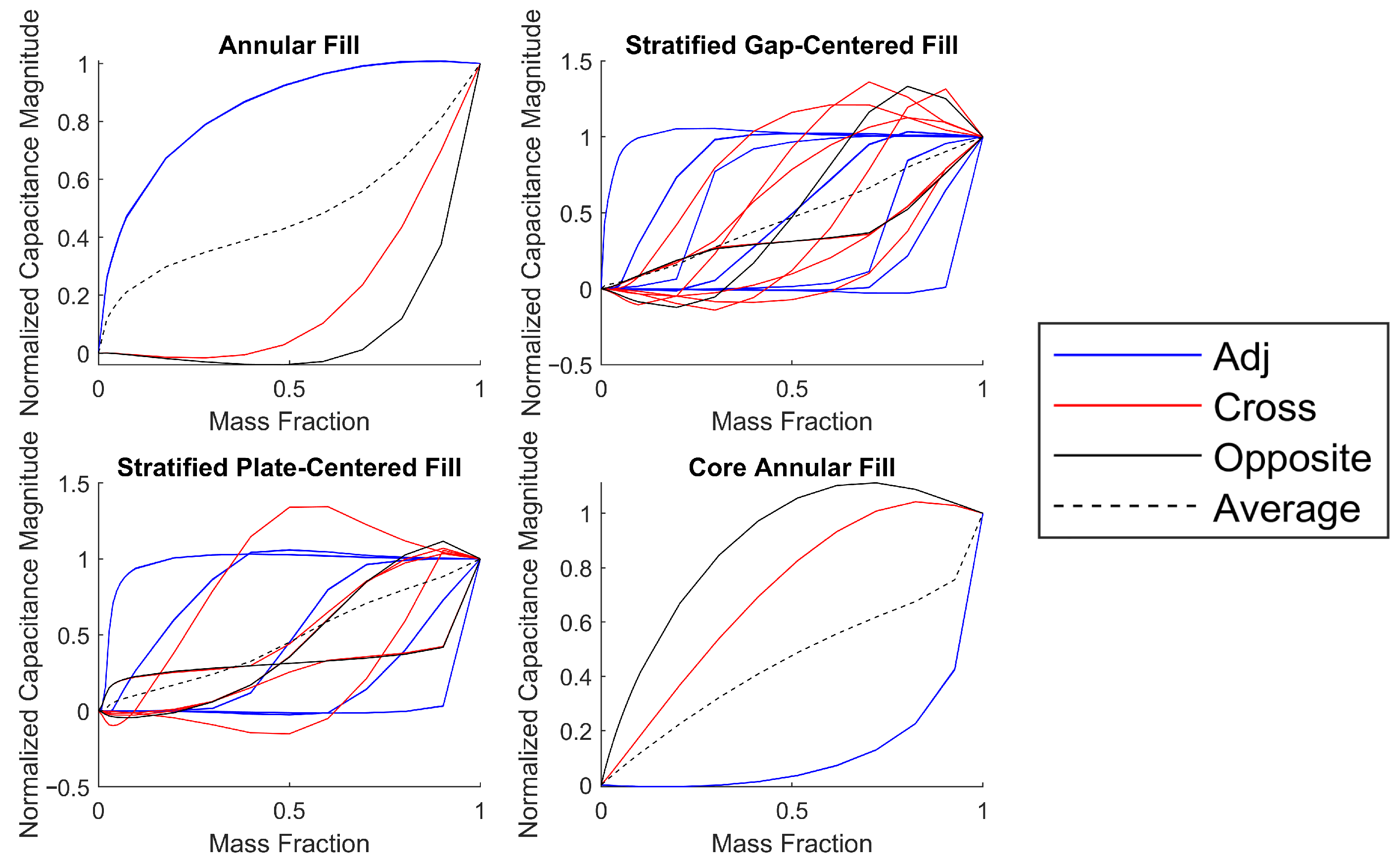
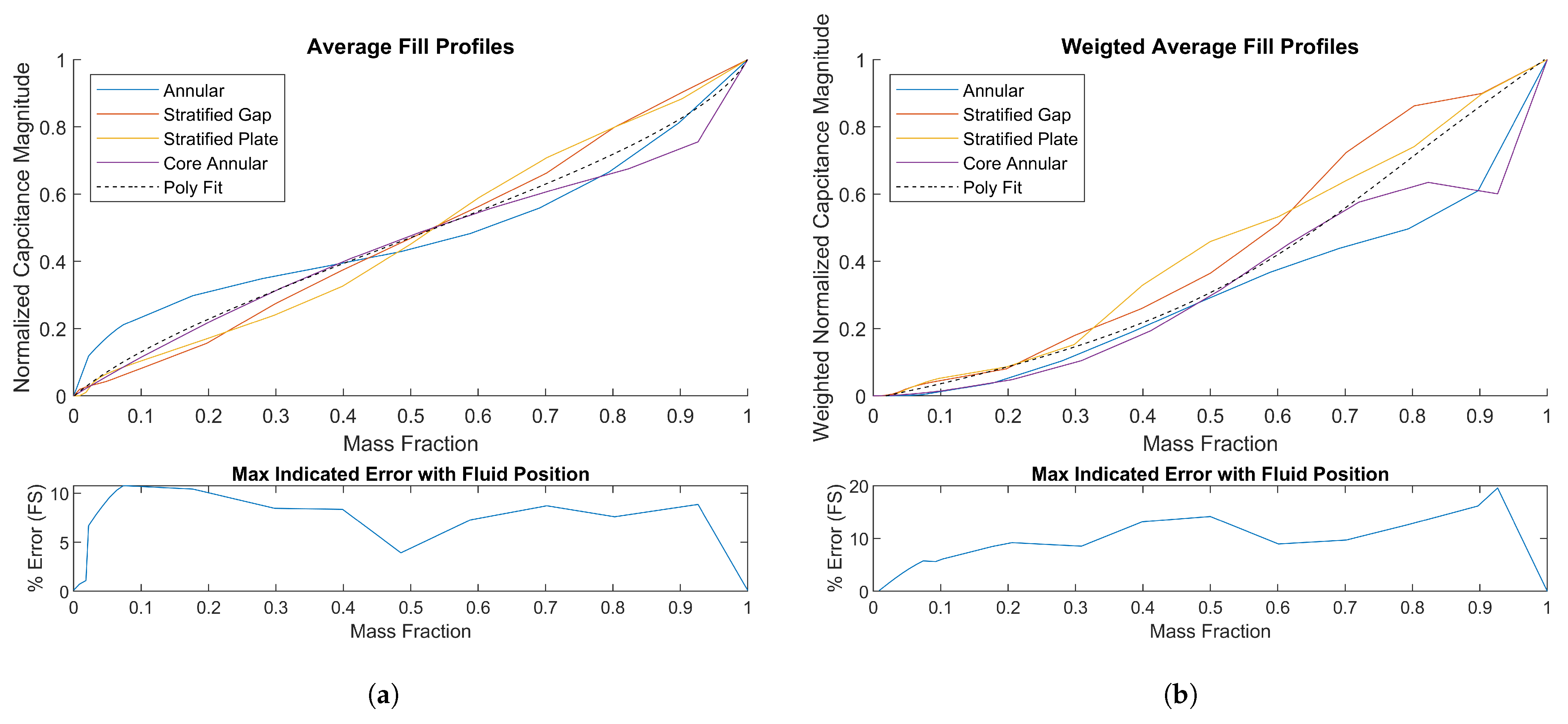
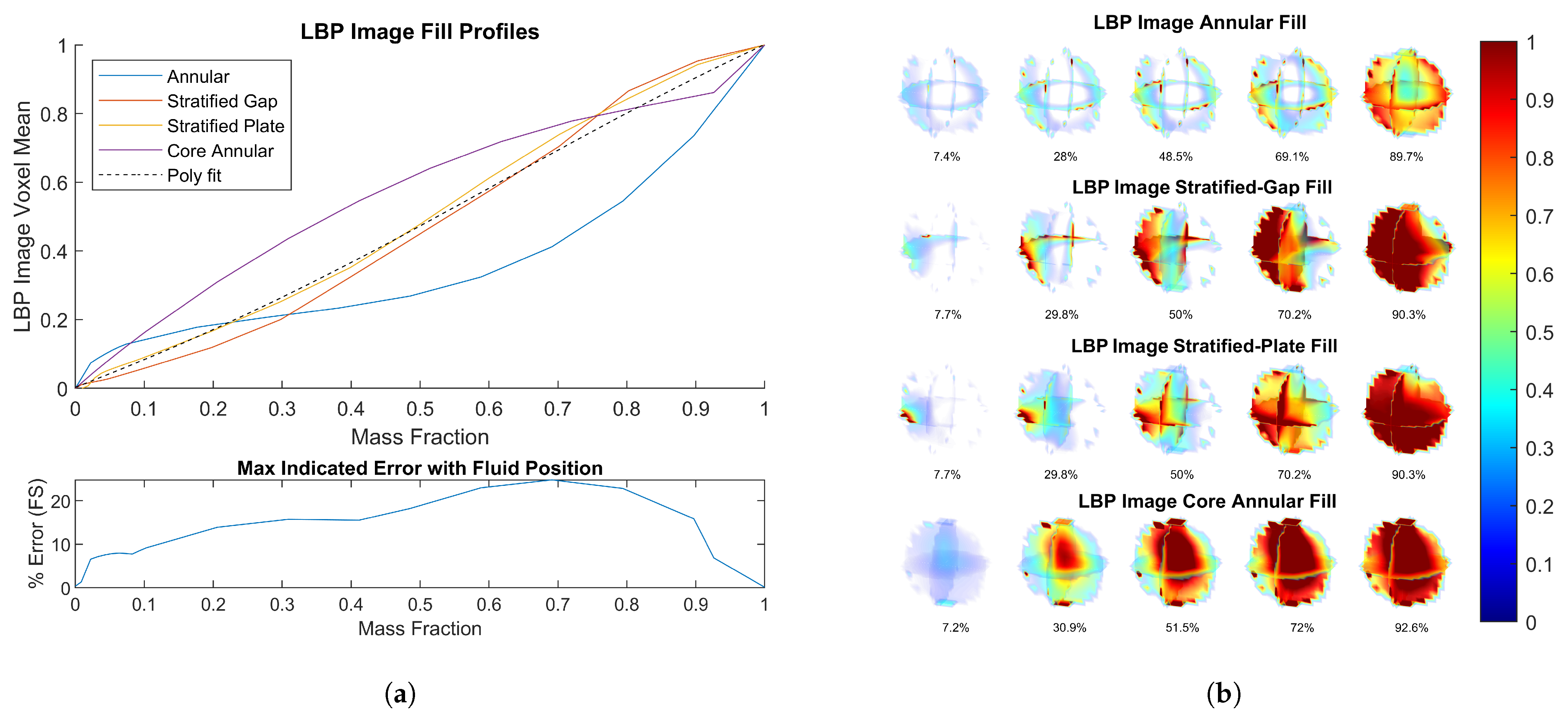
Different fill types may occur under micro-gravity conditions, such as stratified, annular, and core-annular, as shown in
Figure 1b. The ‘stratified’ fill, also known as ‘settled’, may occur under thrusting conditions. The fuel mass may settle at different directions, as indicated by a dotted line in the figure. Two possible positions are considered here for this fill type: settled on a ‘plate’ and settled on a ‘gap’. The annular fill may occur when the fuel sticks to the inner wall of the tank, with possible off-centered conditions, as shown in the figure. Lastly, the core-annular fill may occur when the fuel mass floats inside the tank, with possible off-centered conditions. It is difficult to obtain micro-gravity conditions on Earth. Two common methods for that purpose include drop-tower tests and parabolic airplane flights [
7,
21]. However, computational techniques allow simulating such conditions with great efficiency and accuracy. To this end, the COMSOL Multiphysics 6.0 software is used here to simulate the various fill cases at different mass fractions. A complete list of the different fill types is discussed later in
Section 3.5.

 ,
, 


