
A Review of Lunar Communications and Antennas: Assessing Performance in the Context of Propagation and Radiation

 ,
,  , ,
, ,  ,
,
Abstract
:1. Introduction
2. Lunar Surface Propagation Path Loss Models
3. Lunar Communication Challenges
4. Lunar Antenna Types
4.1. Planar Antennas
4.1.1. Patch Antennas
4.1.2. Slot Antennas
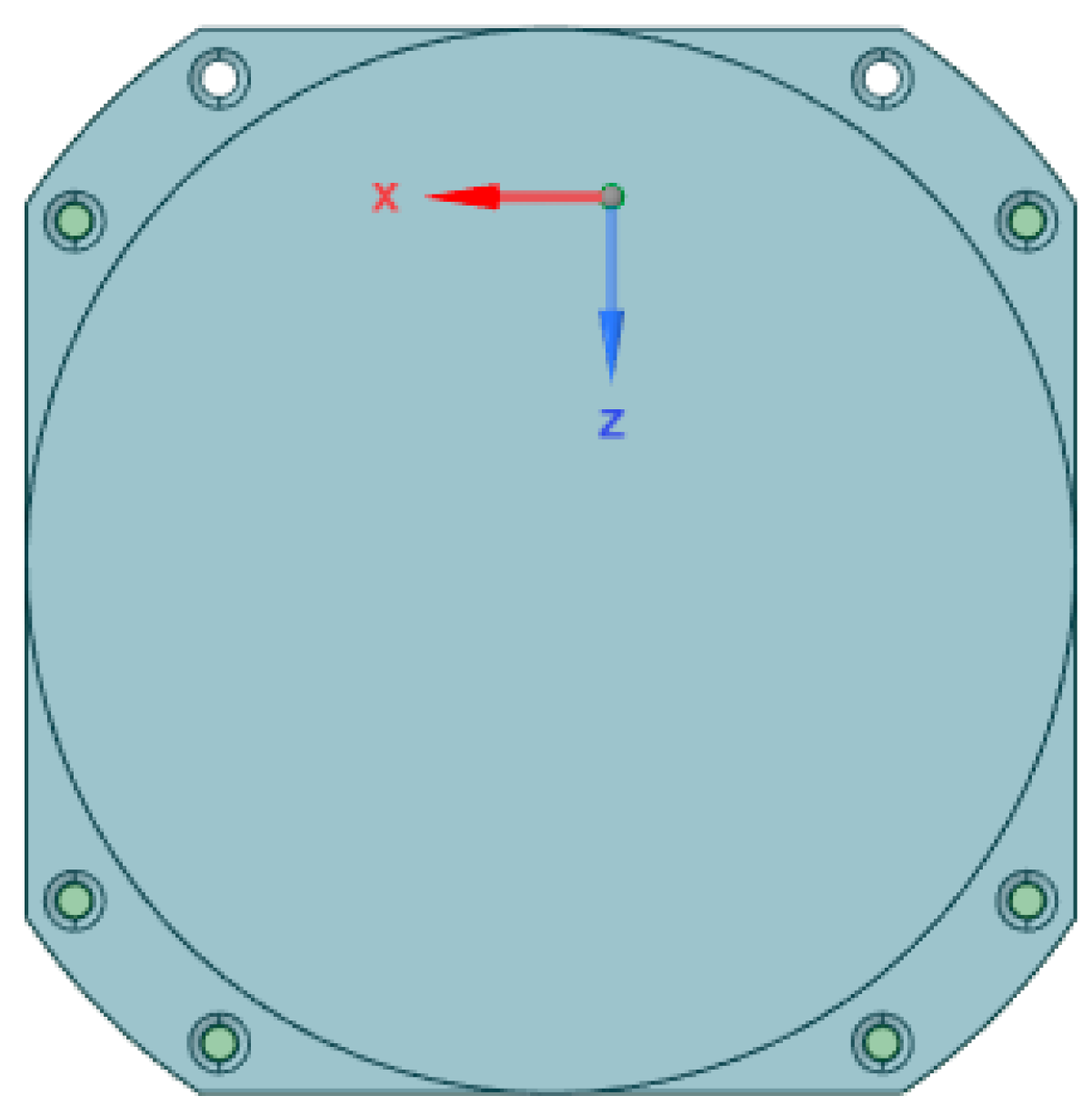
4.1.3. All-Metal Circular Patch Antenna
4.2. Reflector Antennas
4.2.1. Inflatable Impulse-Radiating Antenna (Inf-IRA)
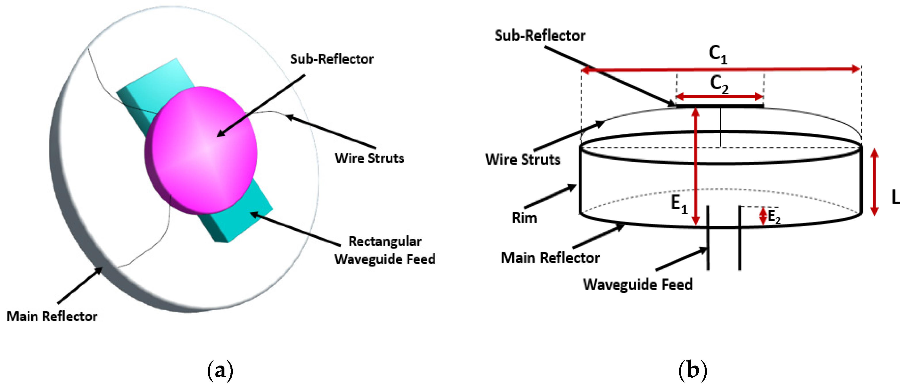
4.2.2. All-Metal Reflector Antennas
4.3. Antennas for Low-Frequency Radio Astronomy
4.3.1. Lunar Gravitational-Wave Antennas (LGWAs)
4.3.2. Polyimide Film Antennas
4.4. Wire Antennas
4.4.1. Dipole Antennas
4.4.2. Monopole Antennas
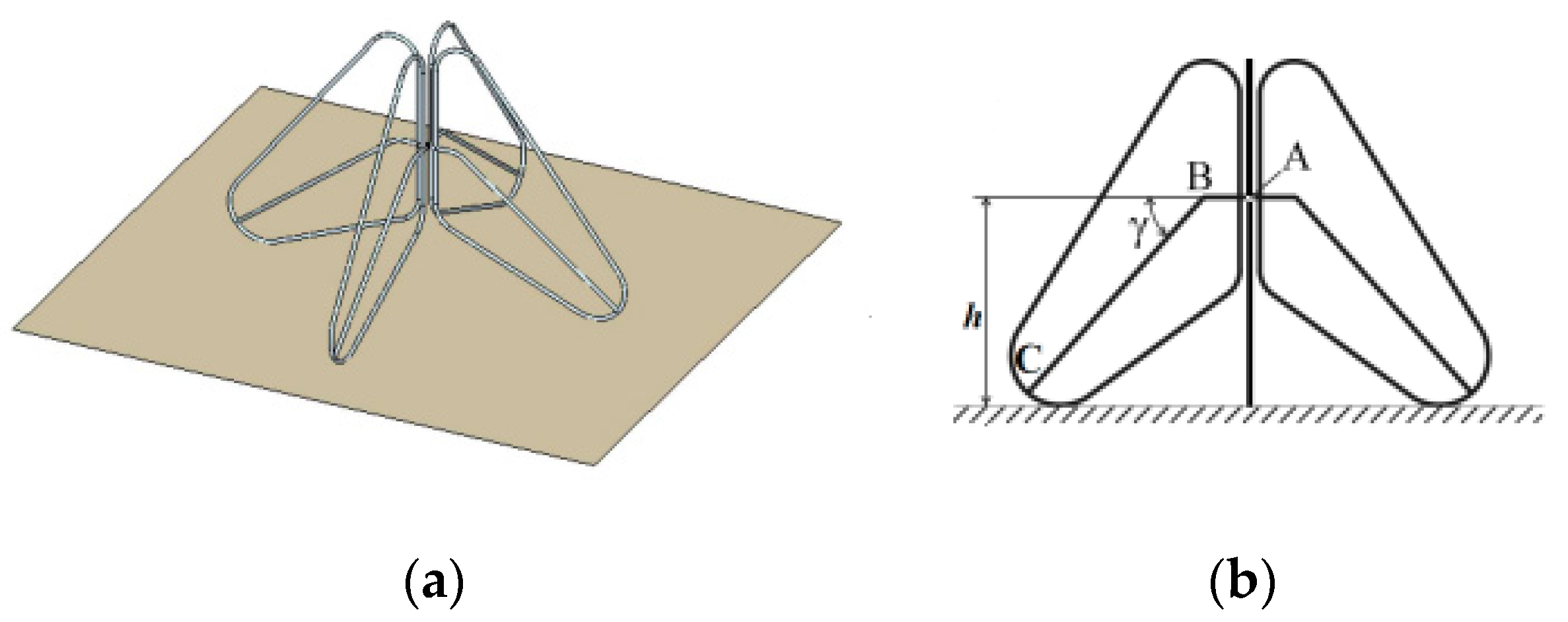
4.4.3. Bow-Tie Antennas
4.4.4. Sleeve Dipole Antennas
5. Discussion
6. Conclusions
Author Contributions
Funding
Institutional Review Board Statement
Informed Consent Statement
Data Availability Statement
Acknowledgments
Conflicts of Interest
References
- Dick, S. NASA 50th Anniversary Proceedings: NASA’s First 50 Years: Historical Perspectives: NASA’s First 50 Years, Historical Perspectives; US National Aeronautics & Space Administration: Washington, DC, USA, 2010; Volume 4704. [Google Scholar]
- Sarkissian, J. On Eagle’s Wings: The Parkes Observatory’s Support of the Apollo 11 Mission. Publ. Astron. Soc. Aust. 2001, 18, 287–310. [Google Scholar] [CrossRef]
- Mission Evaluation Team. Apollo 11 Mission Report; NASA: Washington, DC, USA, 1969. [Google Scholar]
- Science and Technology Division. Astronautics and Aeronautics 1969 Chronology on Science, Technology, and Policy; Library of Congress, Ed.; NASA Historical Division, Office of Policy: Washington, DC, USA, 1970; pp. 3–536. [Google Scholar]
- Flanegan, M.; Gal-Edd, J.; Anderson, L.; Warner, J.; Ely, T.; Lee, C.; Shah, B.; Vaisnys, A.; Schier, J. NASA lunar communication and navigation architecture. In Proceedings of the SpaceOps 2008 Conference, Heidelberg, Germany, 12–16 May 2008. [Google Scholar]
- O’Keefe, S. The Vision for Space Exploration; National Aeronautics and Space Administration: Washington, DC, USA, 2004; pp. 1–38. [Google Scholar]
- Bhasin, K.; Warner, J.; Anderson, L. Lunar Communication Terminals for NASA Exploration Missions: Needs, Operations Cocepts and Architectures. In Proceedings of the 26th International Communications Satellite Systems Conference (ICSSC), San Diego, CA, USA, 10–12 June 2008. [Google Scholar]
- NASA. Artemis Plan “NASA’s Lunar Exploration Program Overview”; NASA: Washington, DC, USA, 2020. [Google Scholar]
- Weisz, K. NASA’s artemis 1 program and recent launch issues. In Skywatchers: Newsletter of the China Astronomical Society; NASA: Washington, DC, USA, 2022; Volume 59, pp. 1–11. [Google Scholar]
- Bailey, B.; Bleacher, J.; Lawrence, S.; Mahoney, E.; Robinson, J.A. The Artemis Program: Enabling Human Exploration of the Moon. In The Impact of Lunar Dust on Human Exploration; LPIB Lunar and Planetary Institute: Houston, TX, USA, 2020. [Google Scholar]
- Kobayashi, T.; Lee, S.R.; Kumamoto, A.; Ono, T. GPR observation of the Moon from orbit: Kaguya Lunar Radar Sounder. In Proceedings of the 15th International Conference on Ground Penetrating Radar, Brussels, Belgium, 30 June–4 July 2014. [Google Scholar]
- Porcello, L.; Jordan, R.; Zelenka, J.; Adams, G.; Phillips, R.; Brown, W.; Ward, S.; Jackson, P. The Apollo lunar sounder radar system. Proc. IEEE 1974, 62, 769–783. [Google Scholar] [CrossRef]
- Potter, N. Chandrayaan-3 Moon Landing: Win for a “New India” It’s only the fourth country ever to manage a successful lunar landing. IEEE Spectrum. 29 August 2023. Available online: https://spectrum.ieee.org/india-lunar-landing (accessed on 4 October 2023).
- Lohn, J.D.; Linden, D.S.; Blevins, B.; Greenling, T.; Allard, M.R. Automated Synthesis of a Lunar Satellite Antenna System. IEEE Trans. Antennas Propag. 2015, 63, 1436–1444. [Google Scholar] [CrossRef]
- Almaeeni, S.; Els, S.G.; Almarzooqi, H. To a dusty Moon: Rashid’s mission to observe lunar surface Processes close-up. In Proceedings of the 52nd Lunar and Planetary Science Conference, Virtually, 15–19 March 2021. [Google Scholar]
- Convenevole, C.; Valigi, N.; Guiglia, F.; Bintoudi, A.D. Lunar SOURCE: Lunar SOUnding Radar Cubesat Experiment. In Proceedings of the 2020 IEEE Aerospace Conference, Big Sky, MT, USA, 7–14 March 2020; pp. 1–10. [Google Scholar]
- Serria, E.; Gadhafi, R.; AlMaeeni, S.; Mukhtar, H.; Copiaco, A.; Abd-Alhameed, R.; Lemieux, F.; Mansoor, W. Lunar Environment Evaluation of Sleeve Antenna. In Proceedings of the 2023 IEEE Conference on Antenna Measurements and Applications (2023 IEEE CAMA), Genoa, Italy, 15–17 November 2023. [Google Scholar]
- Almaeeni, S.; Winter, P.; Almarzooqi, H. Efficient Lunar-Earth communication system based on Software Defined Radio for the Emirates Lunar Mission. In Proceedings of the 72nd International Astronautical Congress, Dubai, United Arab Emirates, 25–29 October 2021. [Google Scholar]
- Santra, S.; Paet, L.B.; Staudinger, E.; Yoshida, K. Radio Propagation modelling for coordination of lunar micro-rovers. In Proceedings of the International Symposium on Artificial Intelligence, Robotics and Automation in Space (I-SAIRAS), Virtual Conference, 19–21 October 2020. [Google Scholar]
- Foore, L.; Ida, N. Path Loss Prediction Over the Lunar Surface Utilizing a Modified Longley-Rice Irregular Terrain Model; NASA: Washington, DC, USA, 2007. [Google Scholar]
- Zhu, Q.; Wang, C.; Chen, X.; Chen, C.; Wang, X.; Zhang, C. Path Loss Prediction Model of Radio Propagation over Lunar Surface. In Proceedings of the International Conference on High Performance Networking, Computing and Communication Systems, Singapore, 5–6 May 2011; pp. 556–562. [Google Scholar]
- Pan, H.; Qiuming, Z.; Cuiwei, X.; Xueqiang, C.; Yu, H. Path loss prediction over lunar surface with obstacle diffraction. In Proceedings of the 2014 IEEE Workshop on Advanced Research and Technology in Industry Applications (WARTIA), Ottawa, ON, Canada, 29–30 September 2014. [Google Scholar]
- Pabari, J.P.; Acharya, Y.B.; Desai, U.B.; Merchant, S.N.; Krishna, B.G. Radio Frequency Modelling for Future Wireless Sensor Network on Surface of the Moon. Int. J. Commun. Netw. Syst. Sci. 2010, 03, 395–401. [Google Scholar] [CrossRef]
- Hwu, S.; Upanavage, M.; Sham, C. Lunar surface propagation modeling and effects on communications. In Proceedings of the 26th International Communications Satellite Systems Conference (ICSSC), San Diego, CA, USA, 10–12 June 2008. [Google Scholar]
- NASA. LRO—Lunar Reconnaissance Orbiter; National Aeronautics and Space Administration: Washington, DC, USA, 2013. [Google Scholar]
- Paige, D.; Foote, M.; Greenhagen, B.; Schofield, J.; Calcutt, S.; Vasavada, A.; Preston, D. The lunar reconnaissance orbiter diviner lunar radiometer experiment. Space Sci. Rev. 2010, 150, 125–160. [Google Scholar] [CrossRef]
- Harms, J.; Ambrosino, F.; Angelini, L.; Braito, V.; Branchesi, M.; Brocato, E.; Cappellaro, E.; Coccia, E.; Coughlin, M.; Della Ceca, R.; et al. Lunar Gravitational-wave Antenna. Astrophys. J. 2021, 910, 1. [Google Scholar] [CrossRef]
- Silburta, A.; Ali-Diba, M.; Zhub, C.; Jacksona, A.; Valenciaa, D.; Kissinb, Y.; Tamayo, D.; Menou, K. Lunar crater identification via deep learning. ICARUS 2019, 317, 27–38. [Google Scholar] [CrossRef]
- Yang, C.; Zhao, H.; Bruzzone, L.; Benediktsson, J.A.; Liang, Y.; Liu, B.; Zeng, X.; Guan, R.; Li, C.; Ouyang, Z. Lunar impact crater identification and age estimation with Chang’E data by deep and transfer learning. Nat. Commun. 2020, 11, 1–15. [Google Scholar] [CrossRef]
- Noble, S. The Lunar Regolith; NASA: Washington, DC, USA, 2003. [Google Scholar]
- McKay, D.S.; Heiken, G.; Basu, A.; Blanford, G.; Simon, S.; Reedy, R.; French, B.M.; Papike, J. The lunar regolith. In Lunar Sourcebook; Cambridge University Press: Cambridge, UK, 1991; pp. 285–356. [Google Scholar]
- Theinat, A.K.; Modiriasari, A.; Bobet, A.; Melosh, H.J.; Dyke, S.J.; Ramirez, J.; Maghareh, A.; Gomez, D. Lunar lava tubes: Morphology to structural stability. ICARUS 2020, 338, 113442. [Google Scholar] [CrossRef]
- Mardon, A.A. Lunar lava tubes and artificial tunnels: Habitations for the near term future. In Proceedings of the Lunar and Planetary Science Conference, Houston, TX, USA, 17–21 March 1997. [Google Scholar]
- Sauro, F.; Pozzobon, R.; Massironi, M.; De Berardinis, P.; Santagata, T.; De Waele, J. Lava tubes on Earth, Moon and Mars: A review on their size and morphology revealed by comparative planetology. Earth-Sci. Rev. 2020, 209, 103288. [Google Scholar] [CrossRef]
- Miaja, P.F.; Navarro-Medina, F.; Aller, D.G.; León, G.; Camanzo, A.; Suarez, C.M.; Alonso, F.G.; Nodar, D.; Sauro, F.; Bandecchi, M.; et al. RoboCrane: A system for providing a power and a communication link between lunar surface and lunar caves for exploring robots. Acta Astronaut. 2022, 192, 30–46. [Google Scholar] [CrossRef]
- Hora, M.; Szalay, J.R.; Kempf, S.; Schmidt, J.; Gru, E.; Srama, R.; Sternovsky, Z. A permanent, asymmetric dust cloud around the Moon. Nature 2015, 522, 324–326. [Google Scholar]
- Krüger, H.; Krivov, A.V.; Sremčević, M.; Grün, E. Impact-generated dust clouds surrounding the Galilean moons. ICARUS 2003, 164, 170–187. [Google Scholar] [CrossRef]
- Abuhdima, E.; Liu, J.; Zhao, C.; Elqaouaq, A.; Comert, G.; Huang, C.-T.; Pisu, P.; Nazeri, A.H. Impact of Dust and Sand on 5G Communications for Connected Vehicles Applications. IEEE J. Radio Freq. Identif. 2022, 6, 229–239. [Google Scholar] [CrossRef]
- Ravat, D.; Purucker, M.E.; Olsen, N. Lunar magnetic field models from Lunar Prospector and SELENE/Kaguya along-track magnetic field gradients. J. Geophys. Res. Planets 2020, 125, e2019JE006187. [Google Scholar] [CrossRef]
- Whipple, E.C., Jr. The signature of parallel electric fields in a collisionless plasma. J. Geophys. Res. 1977, 82, 1525–1531. [Google Scholar] [CrossRef]
- Stubbs, T.J.; Halekas, J.S.; Farrell, W.M.; Vondrak, R.R. Lunar surface charging: A global perspective using Lunar Prospector data. Dust Planet. Syst. 2007, 643, 181–184. [Google Scholar]
- He, Q. Investigation on peculiar SNR variation at TianMa radio telescope. Sci. Rep. 2019, 9, 18421. [Google Scholar] [CrossRef]
- Deal, W.; Qian, Y.; Itoh, T.; Radisc, V. Planar integrated antenna technology. Channels 1999, 4, 5G. [Google Scholar]
- Nessel, J.; Barr, P.; Zaman, A.; Miranda, F. Miniature antennas for lunar and planetary surface communications. In Proceedings of the 2006 IEEE Antennas and Propagation Society International Symposium, Albuquerque, New Mexico, 9–14 July 2006; pp. 631–634. [Google Scholar]
- Lambert, K.M.; Anzic, G.; Zakrajsek, R.J.; Zaman, A.J. An Overview of the antenna measurement facilities at the NASA Glenn Research Center. In Proceedings of the 24th Annual Meeting and Symposium of the Antenna Measurement Techniques Association, Cleveland, OH, USA, 3–8 November 2002. [Google Scholar]
- Oraizi, H.; Jam, A.S. Analysis of the tapered slot antenna by the method of least squares. Iran. J. Sci. Technol. Trans. B-Eng. 2005, 29, B4. [Google Scholar]
- Mousavi, P.; Miners, B.; Basir, O. Wideband L-shaped circular polarized monopole slot antenna. IEEE Antennas Wirel. Propag. Lett. 2010, 9, 822–825. [Google Scholar] [CrossRef]
- Ma, Z.; Chen, J.; Li, C.; Jiang, Y. A monopole broadband circularly polarized antenna with coupled disc and folded microstrip stub lines. EURASIP J. Wirel. Commun. Netw. 2023, 2023, 30. [Google Scholar] [CrossRef]
- Rana, M.M.; Khanom, R.; Rahman, M.M. Design and analysis of Vivaldi antennas. In Proceedings of the 2018 International Conference on Innovation in Engineering and Technology (ICIET), Dhaka, Bangladesh, 27–28 December 2018. [Google Scholar]
- Lu, W.; Li, Y.; Ji, Y.; Tang, C.; Zhou, B.; Fang, G. Ultra-wideband MIMO array for penetrating lunar regolith structures on the Chang’e-5 lander. Electronics 2020, 10, 8. [Google Scholar] [CrossRef]
- Panzer, B. Development of an Electrically Small Vivaldi Antenna: The Cresis Aerial Vivaldi (CAV-A); University of Kansas: Lawrence, KS, USA, 2007. [Google Scholar]
- Guha, D.; Antar, Y.M. Microstrip and Printed Antennas: New Trends, Techniques and Applications; John Wiley & Sons: Hoboken, NJ, USA, 2011. [Google Scholar]
- Kishk, A. Advancement in Microstrip Antennas with Recent Applications; BoD–Books on Demand: Norderstedt, Germany, 2013. [Google Scholar]
- Yektakhah, B. High Resolution through-the-Wall and Subsurface Imaging Using Small Number of Transceivers on Moving Robotic Platforms; University of Michigan: Ann Arbor, MI, USA, 2019. [Google Scholar]
- Rahmat-Samii, Y.; Haupt, R. Reflector antenna developments: A perspective on the past, present and future. IEEE Antennas Propag. Mag. 2015, 57, 85–95. [Google Scholar] [CrossRef]
- Balanis, C. Antenna Theory; John Wiley & Sons: Hoboken, NJ, USA, 2005. [Google Scholar]
- Ha, A.; Kim, K. Inflatable impulse radiating antenna for lunar penetrating radar. In Proceedings of the 9th International Workshop on Advanced Ground Penetrating Radar (IWAGPR), Edinburgh, UK, 28–30 June 2017. [Google Scholar]
- Baum, C. An equivalent-charge method for defining geometries of dipole antennas. In Sensor and Simulation Notes; Defense Technical Information Center: Fort Belvoir, VI, USA, 1969; Volume 72, pp. 90167–90168. [Google Scholar]
- Singh, D.; Pande, D.; Bhattacharya, A. Improved feed design for enhance performance of reflector based impulse radiating antennas. In Sensor and Simulation Notes; Defense Technical Information Center: Fort Belvoir, VI, USA, 2013; Volume 565, p. 15. [Google Scholar]
- Simons, R.N.; Zemba, M.J.; Piasecki, M.T.; Pember, T.C.; Dever, S.M.; Miranda, F.A. All-Metal Antennas for Lunar Exploration. In Proceedings of the 2023 United States National Committee of URSI National Radio Science Meeting (USNC-URSI NRSM), IEEE, Boulder, CO, USA, 10–14 January 2023. [Google Scholar]
- Binion, J.D.; Lier, E.; Hand, T.H.; Jiang, Z.H.; Werner, D.H. A metamaterial-enabled design enhancing decades-old short backfire antenna technology for space applications. Nat. Commun. 2019, 10, 108. [Google Scholar] [CrossRef] [PubMed]
- Ehrenspeck, H.W.; Strom, J.A. Short-backfire antenna-A highly efficient array element. Microw. J. 1977, 20, 47–49. [Google Scholar]
- Kumar, A. Backfire antennas aim at direct broadcast TV. Microwaves 1978, 17, 106–108. [Google Scholar]
- Large, A.C. Short backfire antennas with waveguide and linear fields. Microw. J. 1976, 19, 49–52. [Google Scholar]
- Simons, R.N.; Miranda, F.A. All-Metal Antennas for Applications in Extreme Space Environments. In Proceedings of the 2022 IEEE USNC-URSI Radio Science Meeting (Joint with AP-S Symposium), Denver, CO, USA, 10–15 July 2022. [Google Scholar]
- Jones, D.L.; Lazio, J.; Giersch, L.; Hartman, J.; MacDowall, R.; Stewart, K.; Polisensky, E.; Bradley, R.; Weiler, K.; Burns, J. Low frequency antenna options for the lunar surface. In Proceedings of the 2013 IEEE Aerospace Conference, Big Sky, MT, USA, 2–9 March 2013; pp. 1–9. [Google Scholar]
- Bath, A.; Thakur, A.; Sharma, J.; Prasad, B. Analyzing the different parameters of dipole antenna. Int. J. Electr. Electron. Eng. 2014, 1, 11–15. [Google Scholar]
- Tareq, M.; Alam, D.A.; Islam, M.; Ahmed, R. Simple half-wave dipole antenna analysis for wireless applications by CST microwave studio. Int. J. Comput. Appl. 2014, 94, 21–23. [Google Scholar] [CrossRef]
- Lazio, T.J.W.; MacDowall, R.; Burns, J.O.; Jones, D.; Weiler, K.; Demaio, L.; Cohen, A.; Dalal, N.P.; Polisensky, E.; Stewart, K.; et al. The radio observatory on the lunar surface for solar studies. Adv. Space Res. 2011, 48, 1942–1957. [Google Scholar] [CrossRef]
- Bale, S.D.; Reiner, M.J.; Bougeret, J.-L.; Kaiser, M.L.; Krucker, S.; Larson, D.E.; Lin, R.P. The source region of an interplanetary type II radio burst. Geophys. Res. Lett. 1999, 26, 1573–1576. [Google Scholar] [CrossRef]
- Stanislavsky, L.A.; Bubnov, I.N.; Konovalenko, A.A.; Tokarsky, P.L.; Yerin, S.N. The first detection of the solar U+III association with an antenna prototype for the future lunar observatory. Res. Astron. Astrophys. 2021, 21, 187. [Google Scholar] [CrossRef]
- Zahid Kausar, A.S.M.; Reutens, D.C.; Weber, E.; Vegh, V. Monopole antenna array design for 3 T and 7 T magnetic resonance imaging. PLoS ONE 2019, 14, 4. [Google Scholar]
- Weiner, M.M. Monopole Antennas; CRC Press: Boca Raton, FL, USA, 2003. [Google Scholar]
- Jung, J.; Choi, W.; Choi, J. A small wideband microstrip-fed monopole antenna. In IEEE Microwave and Wireless Components Letters; IEEE: New York, NY, USA, 2005. [Google Scholar]
- Fang, G.-Y.; Zhou, B.; Ji, Y.-C.; Zhang, Q.-Y.; Shen, S.-X.; Li, Y.-X.; Guan, H.-F.; Tang, C.-J.; Gao, Y.-Z.; Lu, W.; et al. Lunar Penetrating Radar onboard the Chang’e-3 mission. Res. Astron. Astrophys. 2014, 14, 1607–1622. [Google Scholar] [CrossRef]
- Kiminami, K.; Hirata, A.; Shiozawa, T. Double-sided printed bow-tie antenna for UWB communications. IEEE Antennas Wirel. Propag. Lett. 2004, 3, 152–153. [Google Scholar] [CrossRef]
- Rahim, M.; Aziz, M.A.; Goh, C. Bow-tie microstrip antenna design. In Proceedings of the 2005 13th IEEE International Conference on Networks Jointly Held with the 2005 IEEE 7th Malaysia International Conf on Communic; 2005. [Google Scholar]
- El-Aziz, D.A.A.; Abouelnaga, T.G.; Abdallah, E.A.; El-Said, M.; Abdo, Y.S.E. Analysis and design of UHF bow-tie RFID tag antenna input impedance. Open J. Antennas Propag. 2016, 04, 85–107. [Google Scholar] [CrossRef]
- Ardakani, M.D.; Tabatabaefar, M. A transparent robust quasi-isotropic circularly polarized antenna for Cub-Sat and outdoor wireless. Eng. Rep. 2020, 2, e12224. [Google Scholar] [CrossRef]
- Bhattacharya, A.; Porwal, A.; Dhingra, S.; De, S.; Venkataraman, G. Remote estimation of dielectric permittivity of lunar surface regolith using compact polarimetric synthetic aperture radar data. Adv. Space Res. 2015, 56, 2439–2448. [Google Scholar] [CrossRef]
- Li, C.; Xing, S.; Lauro, S.E.; Su, Y.; Dai, S.; Feng, J.; Cosciotti, B.; Di Paolo, F.; Mattei, E.; Xiao, Y.; et al. Pitfalls in GPR Data Interpretation: False Reflectors Detected in Lunar Radar Cross Sections by Chang’e-3. IEEE Trans. Geosci. Remote. Sens. 2018, 56, 1325–1335. [Google Scholar] [CrossRef]
- Copeland, M.; Bennet, F.; Birch, M.; Ferguson, K.; Grosse, D.; Rey, N.M.; Travouillon, T. A transmitter and receiver for lunar communications on the anu optical ground station. In Proceedings of the Free-Space Laser Communications XXXV, San Francisco, CA, USA, 30 January–1 February 2023; Volume 12413, pp. 207–213. [Google Scholar] [CrossRef]
- Crossley, D.J.; Murphy, J.T.; Liang, J. Comprehensive analysis of superconducting gravimeter data, GPS, and hydrology modelling in support of lunar laser ranging at apache point observatory, New Mexico. Geophys. J. Int. 2023, 232, 1031–1065. [Google Scholar] [CrossRef]
- Wei, G.; Li, X.; Zhang, W.; Tian, Y.; Jiang, S.; Wang, C.; Ma, J. Illumination conditions near the moon’s south pole: Implication for a concept design of China’s Chang’e- 7 lunar polar exploration. Acta Astronaut. 2023, 208, 74–81. [Google Scholar] [CrossRef]
- Guardabasso, P.; Paternostro, S.; Bedialauneta, P.; Fonteyne, R. Lunar landing necessary building blocks and good practices for a sustainable development of human lunar activities. Acta Astronaut. 2023, 202, 782–790. [Google Scholar] [CrossRef]
- Israel, D.J.; Gramling, C.J. LunaNet Interoperability Specification Document-V5; NASA: Washington, DC, USA, 2023. [Google Scholar]
- Flahaut, J.; van der Bogert, C.H.; Crawford, I.A.; Vincent-Bonnieu, S. Scientific perspectives on lunar exploration in Europe. NPJ Microgravity 2023, 9, 50. [Google Scholar] [CrossRef]


| Ref | Models Considered | ||||||
|---|---|---|---|---|---|---|---|
| Free-Space | Freznel | Reflection | Two-Ray | Diffraction | Irregular Terrain | Multipath | |
| [19] | ✓ | ✓ | ✓ | ✓ | |||
| [20] | ✓ | ✓ | |||||
| [21] | ✓ | ✓ | ✓ | ||||
| [22] | ✓ | ✓ | ✓ | ||||
| [24] | ✓ | ✓ | ✓ | ||||
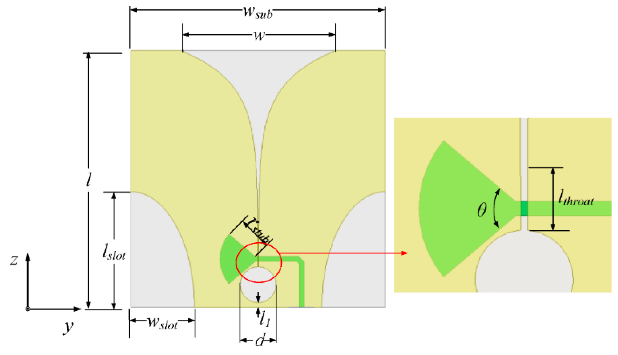
| Parameter | Value (mm) |
|---|---|
| wsub and l | 100 |
| W | 60.8 |
| lslot | 40 |
| wslot | 25 |
| D | 14 |
| lthroat | 4.27 |
| rstub | 15 |
| l1 | 1.7 |
| Antenna Type | Antenna Name | Ref | Frequency Band | Mission/Research | Application |
|---|---|---|---|---|---|
| Planar | CMMA (patch) | [44] | S band | Research | Omnidirectional antenna |
| fHCFA (patch) | [44] | S and Ku bands | Research | Lunar surface network communications and planetary exploratory missions | |
| Vivaldi (array, slot) | [50] | L and S bands | Mission | Lunar regolith penetrating radar | |
| All-Metal Circular Patch Antenna | [18] | S band | Mission | Moon–Earth direct communication |
| Ref | Operating Frequency (MHz) | Bandwidth Fractional (%) | Gain (dBi) | S11 (dB at Centre Frequency) |
|---|---|---|---|---|
| [44] | 2050 | 6.3 | n/a | −24 |
| [44] | 2300 and 16,800 | 0.5 and 3 | n/a | −29 and −27 |
| [50] | 1000–4750 | 130.43% | 2–8 | −15–(−17.5) |
| [18] | 2101.2 and 2266 | 0.004 | 6 | ˂−15 dB |
| Ref | Size mm (W × L × H) | Substrate | er | Software |
|---|---|---|---|---|
| [44] | 12 × 12 × 11 | Duroid 5880 | 2.2 | Zeland’s IE3D electromagnetic simulator |
| [44] | 5 × 5 × 4.5 | Duroid 5880 | 2.2 | Zeland’s IE3D electromagnetic simulator |
| [50] | 100 × 100 × 1 (single antenna) | Polyimide | 3.8 | n/a |
| [18] | 65 (diameter of circular patch) | Aluminium | - | FEKO |
| Parameter | Value |
|---|---|
| C1 | 2λo |
| C2 | 0.6λo–0.7λo |
| L | 0.5λo |
| E1 | 0.6λo |
| E2 | 0.25λo |
| λo | 35.61 mm |
| Antenna Type | Antenna Name | Ref | Frequency Band | Mission/Research | Application |
|---|---|---|---|---|---|
| Reflector | Inflatable Impulse-Radiating Antenna (inf-IRA) | [57] | VHF-S | Research | Radar |
| Backfire (all-metal) | [60] | X-band | Research | Communication and navigation |
| Ref. | Operating Frequency (MHz) | Bandwidth Fractional (%) | Gain (dBi) |
|---|---|---|---|
| [57] | 50–4000 | 195.06 | ≅2–17 |
| [60] | 8920–9400 (cylindrical) 8000–8420 (hexagonal) | 5.24 (cylindrical) 5.11 (hexagonal) | 13.4–15.6 (cylindrical) 12.5–14.2 (hexagonal) |
| Ref. | Size (Diameter in m) | Dielectric Materials Used (If Any) | er | Software |
|---|---|---|---|---|
| [57] | 0.3 | Mylar and Kapton | 2.8–3.7 | FEKO (http://www.feko.info/, accessed on 4 October 2023) |
| [60] | 0.07 | n/a | n/a | Ansys HFSS |
| Antenna Type | Antenna Name | Ref | Frequency Band | Mission/Research | Application |
|---|---|---|---|---|---|
| Wire | Dipole | [69] | HF | Mission | Near-side low radio frequency imaging |
| Small-Sized Active Dipoles | [71] | HF | Research | Lunar radio telescopes | |
| CH1 (monopole) | [75] | VHF | Mission | Lunar penetrating radar | |
| CH2 (bow-tie) | [75] | VHF-UHF | Mission | Lunar penetrating radar | |
| Sleeve Antenna (dipole) | [17] | S | Mission | Lunar surface communication |
| Ref | Operating Frequency (MHz) | Bandwidth Fractional (%) | Gain (dBi) | Size (mm) | Software |
|---|---|---|---|---|---|
| [69] | 1–10 | 163.3 | n\a | 8 × 30.51 | CST 2023 |
| [71] | 1–70 | 194.36 | n\a | 2.8 × 23 | n/a |
| [75] | 40–80 | 66.66 | n\a | n/a | FEKO |
| [75] | 250–750 | 100 | −7.5 | 336 × 120 | FEKO |
| [17] | 2400–2700 | 17.64 | 2.23 | 12 × 159.5 | CST |
| Band | Frequency (GHz) | Application |
|---|---|---|
| UHF Band | 0.3–1 |
|
| S | 2–4 |
|
| X | 8–12 |
|
| Ka | 26.5–40 |
|
| G | 110–300 |
|
Disclaimer/Publisher’s Note: The statements, opinions and data contained in all publications are solely those of the individual author(s) and contributor(s) and not of MDPI and/or the editor(s). MDPI and/or the editor(s) disclaim responsibility for any injury to people or property resulting from any ideas, methods, instructions or products referred to in the content. |
© 2023 by the authors. Licensee MDPI, Basel, Switzerland. This article is an open access article distributed under the terms and conditions of the Creative Commons Attribution (CC BY) license (https://creativecommons.org/licenses/by/4.0/).
Share and Cite
Serria, E.; Gadhafi, R.; AlMaeeni, S.; Mukhtar, H.; Copiaco, A.; Abd-Alhameed, R.; Lemieux, F.; Mansoor, W. A Review of Lunar Communications and Antennas: Assessing Performance in the Context of Propagation and Radiation. Sensors 2023, 23, 9832. https://doi.org/10.3390/s23249832
Serria E, Gadhafi R, AlMaeeni S, Mukhtar H, Copiaco A, Abd-Alhameed R, Lemieux F, Mansoor W. A Review of Lunar Communications and Antennas: Assessing Performance in the Context of Propagation and Radiation. Sensors. 2023; 23(24):9832. https://doi.org/10.3390/s23249832
Chicago/Turabian StyleSerria, Elham, Rida Gadhafi, Sara AlMaeeni, Husameldin Mukhtar, Abigail Copiaco, Raed Abd-Alhameed, Frederic Lemieux, and Wathiq Mansoor. 2023. "A Review of Lunar Communications and Antennas: Assessing Performance in the Context of Propagation and Radiation" Sensors 23, no. 24: 9832. https://doi.org/10.3390/s23249832