Simple Summary
Wireless power transfer using electric coupling can deliver the power by electric field between two metal plates, and a copper plate is generally used for metal material. This study presents that a transparent and flexible metal mesh material can replace the existing copper plate in resonance-based wireless power transfer using electric coupling. In wireless power transfer using electric coupling, a phenomenon called null power point occurs depending on the relative positions of the transmitter and receiver, which negatively affects the efficiency of power transfer. This study also clarified the reason for the occurrence of null power points in the power transfer process.
Abstract
This study provides information on the transfer efficiency of four-plate-structured copper plate and metal mesh sheet couplers, the cause of null-power point. The couplers are compared based on the equivalent circuit model analysis, experimental results of fabricated couplers, and simulation results of the High-Frequency Structure Simulator (HFSS) tool. It was confirmed that the metal mesh material exhibits the same performance as the existing copper plate and can be fully used as a coupler material for the electrical resonance wireless power transfer system. In addition, the null-power point phenomenon is only determined by the main coupling and cross coupling between the transmitter and receiver, which are most dominantly affected by the coupler structure.
1. Introduction
The electrical resonance wireless power transfer (ER-WPT) method transmits power without any direct contact based on alternating electric field coupling between two couplers. The coupler of the magnetic resonance wireless power transfer (MR-WPT) system based on magnetic field coupling incurs a high cost for the system and heavy weight because of a mass of litz wires and ferrite plates. There are other disadvantages, e.g., power loss in coil winding, eddy current loss in the nearby medium, and adverse effects on humans owing to electromagnetic interference [1,2]. In the ER-WPT system, on the other hand, a metal plate is usually used, which makes a lighter coupler than coil and can be implemented at a low cost. In addition, the electric field in ER-WPT can pass through the metal plate without significant power loss [2,3]. The closer the transfer distance, the greater the reduction in the fringing effect, and the electric field is only limited between the metal plates; therefore, it can be safely used regardless of the surrounding environment [4].
ER-WPT is evaluated as an excellent alternative to the MR-WPT method. It is widely used in short-range applications (mW to kW levels), that is, low-power biomedical devices, charging drones, and high-power electric vehicles [5,6,7]. In recent times, to reduce the inductance required for resonance, a high-frequency (MHz or higher) AC voltage source has been used and included a matching network and rectifier structure. The coupler of the ER-WPT system mainly consists of copper and aluminum plates due to the high conductivity and low cost. However, to achieve high-efficiency WPT despite the shape change of the coupler, there has been a recent study of grafting a conductor with high flexibility and transparency. This study has been conducted to improve user convenience in wearable applications [8,9]. However, these studies were conducted using the MR-WPT method only. There is a study that uses graphene film material to ER-WPT for wearable biomedical sensors [10], but the graphene film material is quite different from the metal mesh film material, and the system only implements series resonance without matching. In a recent study about the four-plate coupler ER-WPT system, the coupling capacitance component in the misalignment state was analyzed [11]. However, it only shows the change in each capacitor component in the coupler, with no discussion about the null power point phenomenon, which can occur in the four-plate coupler. The contribution of this study can be summarized in two parts.
- Metal mesh (flexible and transparent material) is used as an ER-WPT coupler and its performance is compared with conventional copper plate material.
- A null power point analysis is conducted and clarifies the reason why the null power point occurs in ER-WPT.
In this study, a four-plate coupler structure is implemented using metal mesh and copper plate materials, and the characteristics of both materials are measured and compared. An analysis of the null power point phenomenon during misalignment is also evaluated using the parameter. Based on actual measurements, it is concluded that a coupler using a metal mesh material can exhibit almost the same characteristics and performance as a copper plate and be used as an ER-WPT coupler material instead of the copper plate. The metal mesh material is more flexible than the copper plate; thus, the shape and structure of the coupler can be designed to be more flexible and lightweight.
2. WPT System Model
2.1. Configuration of ER-WPT System
Figure 1 shows the block diagram of the ER-WPT system to which the proposed capacitive coupler is applied. The AC voltage source generates AC voltage with a desired operating frequency, and the proposed system is designed to possess a resonance frequency of 6.78 MHz. The generated current passes through a matching circuit that matches the impedance of primary and secondary side, and the Lumped-L, which will generate resonance at the desired frequency, and is delivered to the plate of the coupler. The coupler includes a four-plate structure, and the electrical coupling occurring between the plates facing each other operates as a capacitive element. Power can be wirelessly transferred from the primary to the secondary through the electrical coupling.
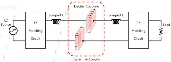
Figure 1.
Block diagram of proposed ER-WPT system.
2.2. Structure of Capacitive Coupler
The four-plate coupler structure shown in Figure 2 is used in the ER-WPT system [12,13,14] and comprises four metal plates, i.e., , and . The horizontal and vertical lengths are and , respectively, and between the two plates is used. and of the proposed coupler each measure 100 mm, and is also designed to be 100 mm.
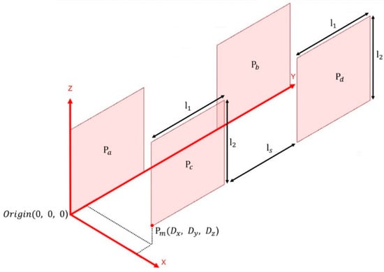
Figure 2.
Parameters of the proposed capacitive coupler.
The and plates are defined as the primary side, and the and plates are arranged as the secondary side. In general, the secondary side is separated from the primary side by , and in a misalignment situation, it can be moved along the and directions (denoted as a misaligned point ).
As seen from Figure 3, the four-plate coupler structure includes six coupling capacitances. and are formed by two facing plates known as main-coupling capacitances. The capacitances formed by the two plates on the same side are self-capacitances (denoted as and ). The capacitances in the opposite direction are known as cross-coupling capacitances (denoted as and ). The equivalent circuit of the four-plate coupler structure can be presented, as shown in Figure 4a, with the mutual capacitance and the equivalent capacitances and on both sides. If and are the voltage that defines the primary port and secondary port voltage, the electric charge of each plate is , , and ; the voltage is defined as , , and . If is set as the reference voltage, i.e., , the primary input voltage can be defined as = , and the secondary output voltage can be defined as . If Kirchhoff’s current law is applied, the relationship between the voltage and current of each plate can be expressed as a matrix, as defined in Equation (1). The self-capacitance components , and are not considered because they are smaller than the capacitance between any two plates [15].
where
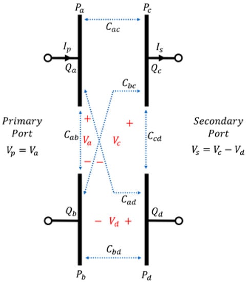
Figure 3.
Physical coupler model.
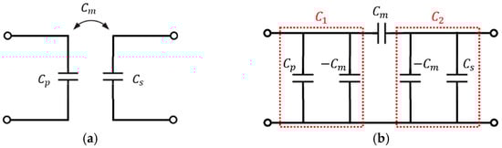
Figure 4.
Circuit model of the capacitive coupler. (a) Basic illustration of the capacitive coupler. (b) Pi model.
The matrix of Equation (1) and the relationship among , and can be expressed as (2) and (3)
Using a similar method, the relationship among , , and can be expressed as
Equations (2) and (3) are combined to obtain equivalent capacitances , , and on the primary and secondary sides, as shown in Figure 4a.
2.3. Measured Equivalent Circuit Model and Power Efficiency
Figure 5 shows the practical equivalent circuit of the ER-WPT system of this study including the Pi model. For resonance in several MHz bands, the parasitic components of the capacitor are not considered because they are negligibly small; however, the parasitic component of an inductor is non-negligible and every parasitic is considered. To define the capacitance based on the actual measured values, six capacitance components between each plate shown in Figure 3 were measured using an RLC meter. The measurement was conducted on the copper plate and metal mesh materials at , and the calculated , and values are listed in Table 1.
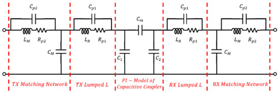
Figure 5.
Practical equivalent circuit model.

Table 1.
RLC Meter Measured Capacitance Components.
As a result of the measurement, the copper plate and metal mesh exhibit almost same capacitances under the same . LCL matching was applied to the fabricated system [6]. The value of the components used in the circuit are listed in Table 2.
Table 2.
Experimental circuit component parameters.
The large external inductor in the transmitter and receiver side is connected in series with a capacitive coupler to decrease the resonant frequency of the system. The combination of and operates like low-pass filter. Therefore, the high-order harmonics components cannot flow into the coupler.
A general two-port network is shown in Figure 6, and the WPT efficiency can be expressed as in [16].
where:
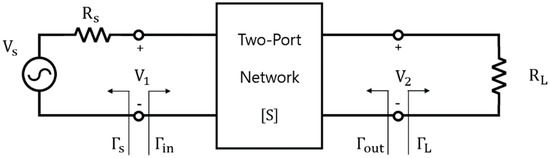
Figure 6.
Block diagram of two-port network [16].
: average power supplied to the network.
: average power supplied to the load.
: reflection coefficient seen looking toward the source.
: reflection coefficient seen looking into Port 2 of the network where Port 2 is terminated by .
: reflection coefficient seen looking into port 2 of the network when port 1 is terminated by .
: reflection coefficient seen looking toward the load.
As the reflection coefficients and are 0 under the condition that the circuit is perfectly resonant, implies the same concept as the efficiency of WPT.
2.4. Null-Power Point and Mutual Capacitance
Since, in mutual capacitive coupling, the higher the better, research has been conducted to increase the mutual capacitance [17]. The null power point is a phenomenon in which transfer characteristics are temporarily lost in a specific misalignment point [18]. It occurs when the becomes zero, and the reason becomes zero in the misalignment situation is that the product of the two main-coupling capacitance components ( and ) and the product of the cross-coupling capacitance components ( and ) become the same as Equation (8).
Therefore, at the point where Equation (8) is satisfied, even though the coupler is located within the effective charging area, power transfer is impossible.
3. Results and Discussion
3.1. Verification of the Proposed Approach
3.1.1. Fabricated Model
Figure 7 shows the fabricated four-plate coupler structure using metal mesh and copper plate for the ER-WPT system. As shown in Figure 7a, a pair of metal mesh couplers is fabricated for the ER-WPT system, and a pair of copper plate couplers of the same size and structure is also fabricated, as shown at the top of Figure 7a. An acrylic structure is used to fix the plate at the desired position. In addition, to place the matching circuit far enough from the coupler, IS680-320 substrate is used, which has and all the conductors were removed except for the copper line. The IS680-320 board is connected to the FR-4 board that contains the Lumped-L and matching circuit through a short wire. The dielectric constant of the FR-4 substrate is , and the parameters of the components listed in Table 2 are attached to the T-shaped copper line structure, as shown in Figure 7b. In the case of the , the two inductors of and are connected in series to match the appropriate inductance. To minimize the parasitic components, the circuit and path should be simplified; however, the circuit structure is designed to improve the convenience of the measurements by replacing various matching circuits without significantly affecting the system. Finally, an SMA connector is used for vector network analyzer (VNA) measurements.
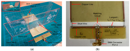
Figure 7.
Fabricated proposed ER-WPT system. (a) Fabricated model. (b) Matching circuit structure.
Figure 8 shows the metal mesh material. The metal mesh material is a transparent electrode made of a micro copper wire and a conductor with light transmittance and flexibility. The metal mesh used in this study has a light transmittance, thickness, and conductivity of 80%, 260 nm, and 1.51E + 06 S/m, respectively.
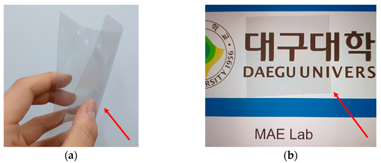
Figure 8.
Metal mesh film characteristics. (a) Flexibility. (b) Transparency.
3.1.2. Experimental and Simulation Results
The simulation using an electromagnetic analysis tool (HFSS) and equivalent circuit analysis program was conducted. The practical equivalent circuit model was used for equivalent circuit (EC) analysis in Figure 5, and all parameters listed in Table 2 and Table 3 were applied for each component. The analysis results were compared and verified with the VNA measurement results.
Table 3.
Plate capacitance value by misalignment.
Figure 9 shows the equivalent circuit model analysis, the experimental results based on the VNA measurements, and the electromagnetic analysis simulation results at the same time. Each result is expressed as an S-Parameter at . Despite applying a matching circuit that resonates at 6.78 MHz, the equivalent circuit model and electromagnetic simulation results have a 9 MHz resonance frequency, unlike the VNA measurement result. The reason for the discrepancy between the simulation (EC, HFSS) and VNA results is that the parasitic capacitance stemming from fabrication influences the system as a self-capacitance component. Even though we considered the parasitic circuit components in Table 2, The additional parasitic components during fabrication also affect the completed model. Except for the resonance frequency mismatch with the VNA measurement results, all results show good agreement. The is improved after matching, and the bandwidth of the resonant frequency is increased.
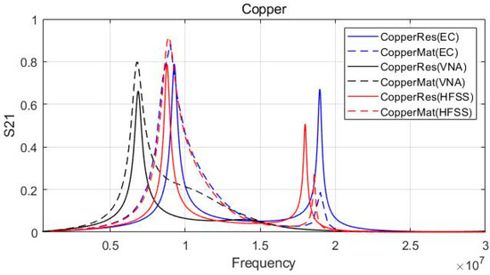
Figure 9.
Experimental and simulation result (copper plate).
Figure 10 shows the results of the metal mesh coupler at . The metal mesh demonstrates almost the same result as using a copper plate. This result validates Table 1 in that the , , and values of the copper plate and metal mesh are nearly identical. Thus, the subsequent simulation results only indicated the metal mesh coupler case. Except for the resonant frequency error of the VNA measurement, it was possible to verify that all three results exhibited similar trends and the magnitude of . Therefore, the results obtained based on the simulation and equivalent circuit analysis can be regarded as reasonable.
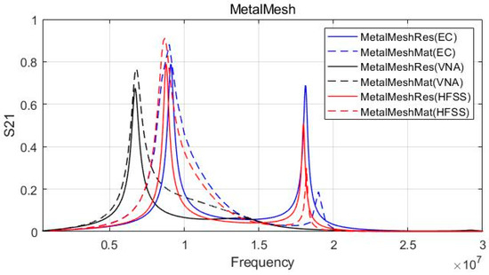
Figure 10.
Experimental and simulation result (metal mesh).
3.2. Power Efficiency Calculated Based on the Proposed Approach
Since it was confirmed in the previous section that the HFSS simulation and equivalent circuit analysis results were reliable, the transmission characteristics of the coupler were analyzed at various distances and misalignment cases. To evaluate the transmission characteristics, the and were plotted.
Figure 11 shows the maximum values of before and after matching based on the of the metal mesh coupler. swept from 5 to 300 mm. The efficiency of the metal mesh after matching significantly improved by 0.2–0.25 compared to without matching. had a high value of 10 pF at , but exponentially decreased to 1 pF when increased from 5 to 50 mm. As the increased beyond, it gradually converged to 0 pF. When changed from 10 mm to 50 mm, there was sharp decrease in efficiency both after and before matching, i.e., 0.87–0.71 and 0.68–0.54, respectively. When changed from 50 mm to 300 mm, the efficiency gradually decreased from 0.71 to 0.59 and 0.54 to 0.34 after and before matching, respectively. A similar trend for and was also observed.
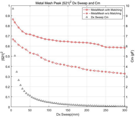
Figure 11.
Efficiency and mutual capacitance variation under distance () sweep: 5–300 mm.
Figure 12 shows the maximum values of before and after matching with 0 to 300 mm and misalignment case. is fixed at 10 mm in every case. In and misalignment situations, the efficiency after matching remarkably improved (0.1–0.25) compared to without matching. Both values for the change of and rapidly decreased from 5 to 0.8 pF together until and . After the exceeded 100 mm, the gradually converged to 0 pF until 300 mm. The efficiency before and after matching in the misalignment tended to uniformly decrease. Consequently, in the case of the misalignment, the efficiency and variation exhibited a similar decreasing trend with the sweep in Figure 11. After the exceeded 100 mm, the sharp decrease of was not alleviated, unlike the of the misalignment. Then, the value became 0 pF at and slightly increased to 0.3 pF until 200 mm. The value of the misalignment demonstrated a clear difference from the of and in that it became zero at . Until , the efficiency before and after matching gradually decreased from 0.65 to 0.58 and 0.75 to 0.69, respectively. Although the after matching efficiency still gradually decreased in the range from 80 mm to 120 mm, the before matching efficiency started to decrease exponentially from 80 mm. In the end, both efficiencies simultaneously reached zero at = 135 mm. There was a noticeable increase in the efficiency between 135 and 160 mm, where it returned to the same level of efficiency as before, i.e., 0.39 and 0.65 for before and after matching, respectively. Both efficiencies slightly increased up to 200 mm and continued to decrease until 300 mm. As seen from this result, if only a minimum of exists, a moderate level of efficiency of 0.6–0.65 can be achieved with matching alone. However, in order to increase the transfer efficiency of the system above 0.65, the matching condition alone is not enough and the needs to be much larger; thus, the value of needs to be lower in a misalignment situation. These characteristics can be selected according to the user application as a trade-off.
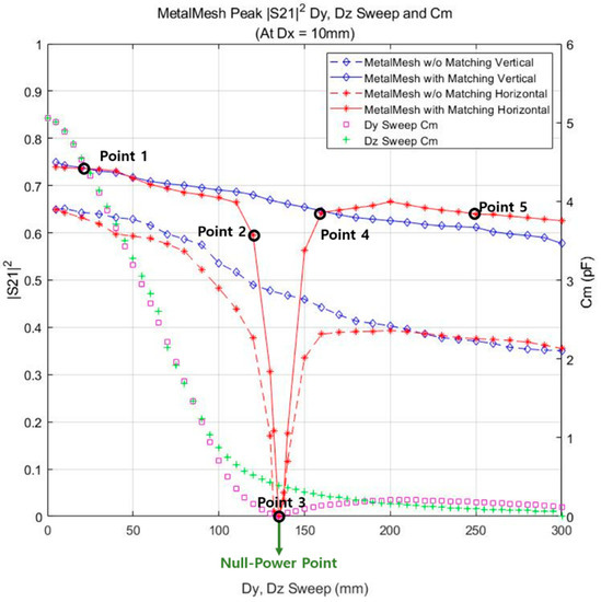
Figure 12.
Efficiency and mutual capacitance variation under distance () sweep: 0–300 mm.
3.3. Null Power Point
Depending on the misalignment direction, certain cross-capacitance components can rapidly increase, and during the main-coupling capacitance components can significantly decrease. From the specific misalignment point, the cross-coupling component becomes more dominant than the main-coupling component in determining . This is known as the null power point and refers to the point where the coupling is not properly formed even if the receiver is within the effective charging area.
In the proposed ER-WPT system, the null power point can be observed at . Table 3 lists the main and cross-capacitor components and for five points around the null power point. points were selected around 135 mm. The absolute values are taken to prevent from being negative. As seen from Table 3, the is larger than the at Point 1, which means main-coupling is much more dominant to compose . At Point 2, the component is still larger than the component; however, the difference is not significant. The becomes equal to at Point 3, which can be defined as the null power point. After Point 3, the dominant component constituting is the . At five points, cm is calculated as 4.528, 0.156, 0.006, 0.134, and 0.18 pF, respectively. In conclusion, the null power point does not occur unless the cross-capacitance component becomes larger than the main-coupling capacitance.
4. Conclusions
In this study, the four-plate structure consisting of copper plates and a metal mesh coupler for the ER-WPT system was implemented and measured. The validity was confirmed by comparing them with the HFSS simulation and the circuit analysis results using the Pi model. As a result, it was confirmed that the coupler using the metal mesh material exhibited the same performance as the copper plates. Therefore, the metal mesh material can be used as a substitute for the copper plate. It can be applied to various applications that cannot be realized with conventional copper plates, such as watchstraps, wearable biomedical devices, and curved electric devices. The analysis of the null power point was also conducted. The cause of the null power point is that the mutual capacitance becomes zero at the point where the product component of the cross-capacitances becomes larger than the product component of the coupling capacitances; it occurs in ER-WPT systems with multiple plates. This phenomenon is only determined by the structure of the coupler and is not related with any other factors, such as matching state or circuitry characteristics. In this study, the null power is found at ; however, it may vary depending on the shape and design of the coupler. In order to overcome the null power point phenomenon, it is necessary to design a coupler with a large difference between the main-coupling and the cross-coupling even when the system is in a misalignment state. The specific coupler design for overcoming the null power point can be dealt with in future work.
Author Contributions
Data curation, H.B.; validation, H.B.; investigation, K.B. and S.P.; formal analysis, H.B.; visualization, K.B.; software, K.B.; writing—original draft preparation, K.B.; writing—review and editing, S.P.; supervision, S.P. All authors have read and agreed to the published version of the manuscript.
Funding
This work was supported by the Daegu University of the Republic of Korea (No. 2019-0589).
Institutional Review Board Statement
Not applicable.
Informed Consent Statement
Not applicable.
Data Availability Statement
Not applicable.
Conflicts of Interest
The authors declare no conflict of interest.
References
- Covic, G.A.; Boys, J.T. Modern Trends in Inductive Power Transfer for Transportation Applications. IEEE J. Emerg. Sel. Top. Power Electron. 2013, 1, 28–41. [Google Scholar] [CrossRef]
- Yan, Z.; Zhang, Y.; Kan, T.; Lu, F.; Zhang, K.; Song, B.; Mi, C.C. Frequency Optimization of a Loosely Coupled Underwater Wireless Power Transfer System Considering Eddy Current Loss. IEEE Trans. Ind. Electron. 2018, 66, 3468–3476. [Google Scholar] [CrossRef]
- Chen-Yang, X.; Chao-Wei, L.; Juan, Z. Analysis of power transfer characteristic of capacitive power transfer system and inductively coupled power transfer system. In Proceedings of the 2011 International Conference on Mechatronic Science, Electric Engineering and Computer (MEC), Jilin, China, 19–21 August 2011; pp. 1281–1285. [Google Scholar]
- Maji, S.; Sinha, S.; Regensburger, B.; Monticone, F.; Afridi, K.K. Reduced-Fringing-Field Multi-MHz Capacitive Wireless Power Transfer System Utilizing a Metasurface-based Coupler. In Proceedings of the 2020 IEEE 21st Workshop on Control and Modeling for Power Electronics (COMPEL), Aalborg, Denmark, 9–12 November 2020; pp. 1–6. [Google Scholar]
- Tarek, M.T.; Muharam, A.; Hattori, R. Wireless battery charging system for drones via capacitive power transfer. In Proceedings of the 2017 IEEE PELS Workshop on Emerging Technologies: Wireless Power Transfer (WoW). IEEE, Chongqing, China, 20–22 May 2017; pp. 1–6. [Google Scholar]
- Koruprolu, A.; Nag, S.; Erfani, R.; Mohseni, P. Capacitive Wireless Power and Data Transfer for Implantable Medical Devices. In Proceedings of the 2018 IEEE Biomedical Circuits and Systems Conference (BioCAS), Cleveland, OH, USA, 17–19 October 2018; pp. 1–4. [Google Scholar]
- Zhang, H.; Lu, F.; Hofmann, H.; Liu, W.; Mi, C.C. A four-plate compact capacitive coupler design and LCL-compensated topology for capacitive power transfer in electric vehicle charging application. IEEE Trans. Power Electron. 2016, 31, 8541–8551. [Google Scholar] [CrossRef]
- Kang, S.H.; Park, S.; Jung, C.W. Textile resonators using a sintered metal conductor for wearable MR-WPT with high efficiency and wearability. Microw. Opt. Technol. Lett. 2017, 59, 668–672. [Google Scholar] [CrossRef]
- Lee, H.H.; Jung, C.W. Magnetic resonant-wireless power transfer for transparent laptop applications using μ-metal mesh film. Microw. Opt. Technol. Lett. 2017, 59, 2781–2785. [Google Scholar] [CrossRef]
- Yang, L.; Feng, B.; Zhang, Y.; Li, X.; Zhang, L.; Chen, X.; Nie, J.; Wen, H.; Tian, J.; Jian, J.; et al. Single Wire Capacitive Wireless Power Transfer System for Wearable Biomedical Sensors based on Flexible Graphene Film Material. IEEE Trans. Biomed. Circuits Syst. 2022, 1–11. [Google Scholar] [CrossRef] [PubMed]
- Reatti, A.; Pugi, L.; Corti, F.; Grasso, F. Effect of misalignment in a four plates capacitive wireless power transfer system. In proceedings of the 2020 IEEE International Conference on Environment and Electrical Engineering and 2020 IEEE Industrial and Commercial Power Systems Europe (EEEIC / I&CPS Europe), Madrid, Spain, 9–12 June 2020.
- Lu, F.; Zhang, H.; Hofmann, H.; Mi, C.C. A Double-Sided LC-Compensation Circuit for Loosely Coupled Capacitive Power Transfer. IEEE Trans. Power Electron. 2017, 33, 1633–1643. [Google Scholar] [CrossRef]
- Lu, F.; Zhang, H.; Hofmann, H.; Mi, C. A Double-Sided LCLC-Compensated Capacitive Power Transfer System for Electric Vehicle Charging. IEEE Trans. Power Electron. 2015, 30, 6011–6014. [Google Scholar] [CrossRef]
- Masuda, M.; Kusunoki, M.; Umegami, H.; Hattori, F.; Yamamoto, M. Wireless Power Transfer via Electric Field Resonance Coupling. J. Jpn. Inst. Electron. Packag. 2015, 18, 327–330. [Google Scholar] [CrossRef][Green Version]
- Huang, L.; Hu, A. Defining the mutual coupling of capacitive power transfer for wireless power transfer. Electron. Lett. 2015, 51, 1806–1807. [Google Scholar] [CrossRef]
- Pozar, D.M. Microwave Engineering, 4th ed.; John Wiley & Sons: Hoboken, NJ, USA, 2011; pp. 558–563. [Google Scholar]
- Park, C.; Park, J.; Shin, Y.; Kim, J.; Huh, S.; Kim, D.; Park, S.; Ahn, S. Separated Circular Capacitive Coupler for Reducing Cross-Coupling Capacitance in Drone Wireless Power Transfer System. IEEE Trans. Microw. Theory Tech. 2020, 68, 3978–3985. [Google Scholar] [CrossRef]
- Bertoluzzo, M.; Buja, G.; Dashora, H. Avoiding null power point in DD coils. In Proceedings of the IEEE PELS Workshop on Emerging Technologies: Wireless Power Transfer (WoW), London, UK, 18–21 June 2019. [Google Scholar]


Disclaimer/Publisher’s Note: The statements, opinions and data contained in all publications are solely those of the individual author(s) and contributor(s) and not of MDPI and/or the editor(s). MDPI and/or the editor(s) disclaim responsibility for any injury to people or property resulting from any ideas, methods, instructions or products referred to in the content. |
© 2023 by the authors. Licensee MDPI, Basel, Switzerland. This article is an open access article distributed under the terms and conditions of the Creative Commons Attribution (CC BY) license (https://creativecommons.org/licenses/by/4.0/).