1. Introduction
Robotic manipulators have found widespread utilization in industry and logistics, and are nowadays expanding their field of application to other areas like medicine, agriculture and services. At least in part, this expansion is a consequence of the development of sensors and controller devices that allow the robot to be more aware of its environment, and to assume tasks in collaboration with human operators while guaranteeing their safety. However, the mechanical structure of commercially available robots had little evolution during the past few decades. The rigid link serial chain structure, in its several kinematic variants, has remained the standard for high working volume and high dexterity applications. This kind of structure allows for high positioning precision and accuracy with relatively low control complexity, but it has the important limitation of requiring large workspace clearances in order for the robot to assume the postures required to execute a task.
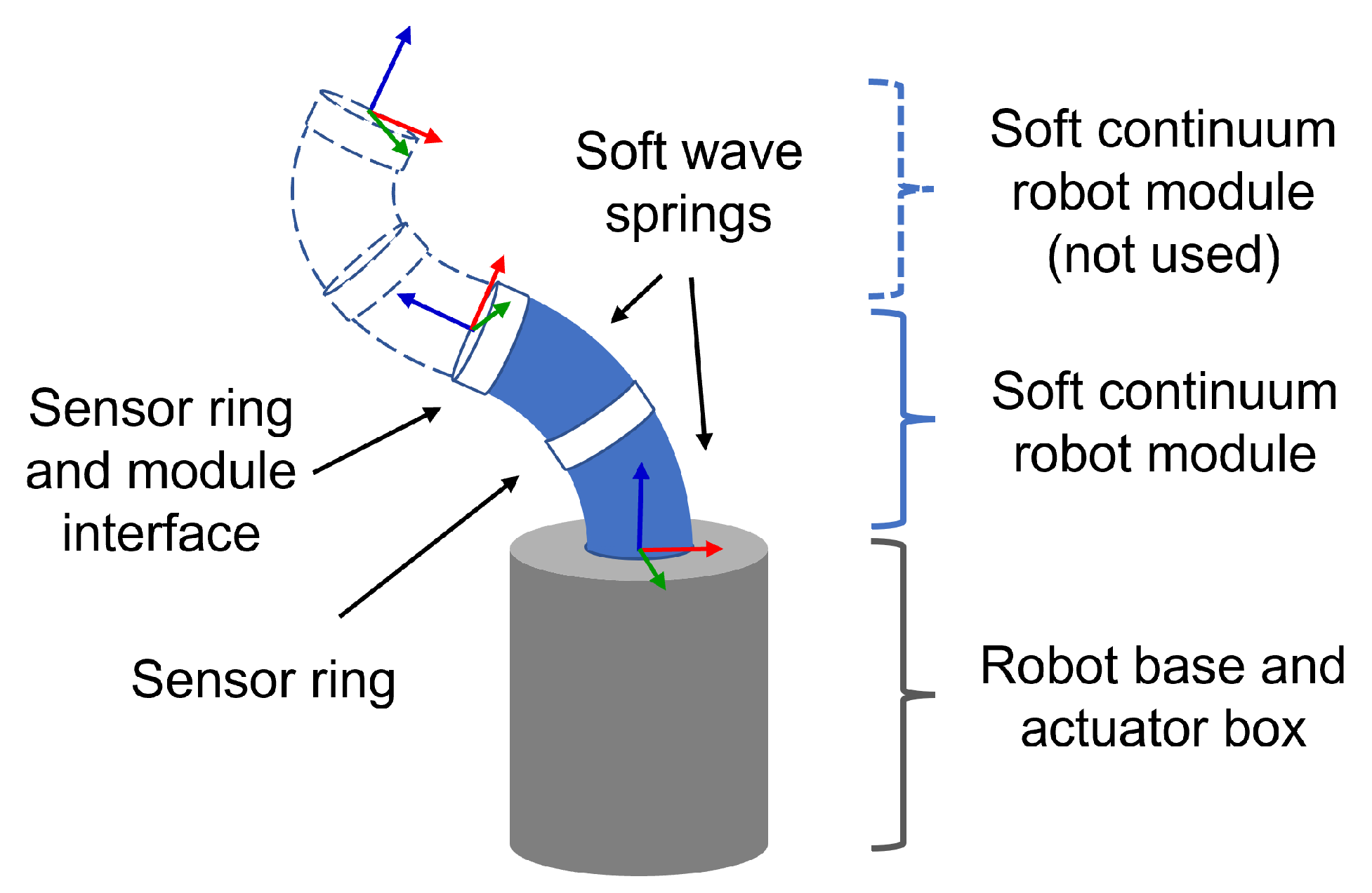
Continuum manipulator robots offer an alternative to the classical manipulator structure. They are composed of a set of deformable modules that are able to bend along the longitudinal axis, and in some cases also to extend and contract. For enhanced working volume and dexterity, the modules are usually assembled in a serial chain configuration like the one depicted in
Figure 1. They are classified as under-actuated robots, because there will be a finite set of actuators controlling the infinite number of degrees of freedom (DoF) provided by the deformable structure. This also means that the robot will exhibit some form of passive mechanical compliance due to the non-actuated DoFs. Extensive research on these robots has been done in the past few decades and relevant literature reviews can be found for instance in [
1,
2,
3,
4]. Soft continuum manipulators (SCMs) have appeared in the literature more recently [
5,
6,
7,
8], and have the distinctive feature of including (sometimes exclusively) soft elastomer materials in the robot structure.
While one may argue that continuum manipulators are not ideal for precision or high-speed tasks like the ones frequently encountered in industry, the passive compliance and controlled deformability of the structure can be an advantage when working on collaborative tasks or in confined workspaces. The former can allow the robot to explore the environment tactilely, or interact safely with users without need for controller supervision (passive safety), while the latter allows the robot to adapt its postures to restricted or cluttered working environments. Both of these are relevant features, for instance, in assistive robots, that are meant to be deployed in a common household and interact with the user, and also do not require sub-millimetre precision to perform their tasks.
In order to fulfil the potential of continuum robots, the theoretically infinite number of DoFs of the structure prompts the need for more sophisticated proprioceptive sensing devices and control laws than the classic manipulator. Many examples in the literature resort to external cameras or 3D positioning devices in order to get precise information about the robot posture, for instance [
5,
6,
8,
9]. However, these sensors require an external mechanical fixture, and also in some cases an unobstructed view of the robot, thus limiting the advantages for work in confined spaces. This implies an obvious need for internal sensors that can provide proprioceptive information, with enough precision and reliability to estimate the robot posture, while maintaining the original advantages of the mechanical structure. In [
10] a review of sensing technologies applied to soft robots is provided, where the authors classify sensors found in the literature according to the respective physical principles of operation. These are classified into five major categories, namely: resistive and piezoresistive sensors, capacitive sensors, optical sensors, magnetic sensors and also inductive sensors. The sensor implementation technologies can also be identified and include conductive liquids, conductive textiles, hydrogels, nanocomposite materials, optical fibres and piezoelectric film, amongst others. A more recent review focused on robots for surgical applications can be found in [
11]. All these technologies and operation principles have their advantages and disadvantages. In general, sensors that depend on high deformations of a hyperelastic base material will tend to suffer from its drawbacks such as, for instance, significant hysteresis, highly nonlinear elasticity and long recovery times. This may also be the case for fluidic sensors that have channels embedded in such materials, or optical strain sensors. Temperature drift may also be a problem, for instance, for resistive sensors. Capacitive and magnetic sensors are especially sensitive to environmental variables like the proximity of conductive objects, externally induced magnetic fields and other sources of interference. Additionally, some of the physical operation principles are multidimensional in nature and decoupling of the desired measurement may be a difficult task. Such is the case, for instance, of capacitive and optical strain sensors that rely on the Poisson effect of a stretching material to measure longitudinal displacement, but are also sensitive to pressure applied in a perpendicular direction.
In more recent literature these and other methods have been used to estimate the shape of continuum robot structures. In [
12] an inductance-based sensor is used to estimate the extension and contraction of the bellows that actuate each continuous module. A set of coils are wrapped around the bellows’ smaller diameter, and the inductance variation is measured. The modules are actuated in bending only, and have a neutral axis length of 19.7 cm. A root mean square (RMS) error of
° regarding the orientation of a single module is reported, together with a 1.3 mm error for a lateral displacement of 14 mm when a perpendicular external load is applied at the distal end. Other concepts based on the variable inductance of coils or helical springs have been proposed in [
13,
14,
15]. In [
15], a helical spring sensor is used on a continuum robot with 140 mm length and 20 mm diameter actuated in bending only. A mean error of 5 mm in the desired radius of curvature is reported using open loop control, and is reduced to 2 mm when using closed loop control. In [
16,
17] magnetic sensors are used to detect the posture change of small permanent magnets embedded in the structure of the robots. In [
16] the robot has two modules; the proximal module has a length of 100 mm and the distal module 95 mm, both with 30 mm diameter. The robot is actuated in bending only. Maximum and minimum errors of 9.339 mm and 0.227 mm, respectively, are reported for tip position estimation. In [
17] the robot also has two modules, but the proximal module has a diameter of 53 mm and the distal module 41 mm. Both have the same length of 118 mm. The modules can be actuated in bending as well as extension/contraction. The robot is used to study the possibility of tactile exploration of the environment, and the sensor measurements are compared only with a theoretical model. Mean errors of ±2 mm are reported for this case when no obstacle is present. In [
18] a resistive sensor composed of a conductive elastomer coiled around an elastic substrate is proposed. The sensor is implemented on a pneu-net actuator to estimate bending. In [
19] a data-driven method for shape estimation of continuum manipulators using Fiber Bragg Grating optical sensors is proposed. The manipulator has a single module with 35 mm length and 6 mm diameter. The authors report a mean error of 0.11 mm estimating tip position for the data driven approach, that compares with a mean error of 1.9 mm for large deflections using a conventional deformation model. In [
20] ionic liquid sensors are used to estimate the tip position of a continuum robot with two active segments, with bending capability only. Each segment has 13 mm diameter and 65 mm length. Estimation errors of 1.5% and 2.5% of the total length are reported for isolated motions and 3D trajectories, respectively. In [
21] shape estimation of a continuum robot is obtained using passive tendons, a concept introduced in [
22]. The robot structure has a single module with 115 mm length and a square section with 15 mm width, capable of deforming in bending and twisting. A total of 20 passive tendons are embedded in the structure, each tendon having one tip attached to the deformable section and the other tip free to displace longitudinally beyond the base structure of the robot. By attaching the passive tendons at different sections along the length of the robot, and different points in each section, their free displacement beyond the base provides information about the deformation of the module. When a curvature is imposed to the structure the tendon displacements are measured using cameras, and an estimation of the shape and tip displacement of the module is computed. In the three experiments reported, tip position errors of 3.6 mm, 2.5 mm and 4.1 mm were obtained by comparing with ground truth values directly measured by another camera. Twisting displacement was also studied, with a reported error of
° for an imposed tip rotation of ≈45°.
With the exception of [
21], recent literature seems to explore the same sensor principles and technologies mentioned in [
10], albeit with different approaches to practical implementation and in some cases with improved results. In this work we adopt the concept of passive tendons, where the tendons are flexible magnetic scales similar to the ones used in industrial linear magnetic encoders. Encoder sensors are embedded in the robot structure following the path of each scale in order to measure the relative displacement between sensors. Knowledge of these distances allows the estimation of the curvature and tip position of one module. This approach requires only three passive tendons that can extend through any number of modules used in the robot, and does not require an additional apparatus at the base in order to measure the displacements. Because the magnetic scales slide almost freely inside the robot structure, drawbacks that usually would arise from high deformation of sensor base materials are not present. Interference from external magnetic fields can still affect the measurement. However, because the distance between sensors and scale is approximately constant, the amplitude and relative phase of the encoder signals is predictable and can be used, in principle, to minimize the influence of external noise. The main drawbacks of the proposed sensors are the ones associated with the utilization of passive tendons and permanent magnet materials in the robot structure. Namely, one needs to store the excess length of the passive tendons when the robot is in a contracted posture and the robot cannot operate in environments where the presence of ferromagnetic materials is not acceptable. These sensors were integrated in a SCM module based on the geometry of a wave spring with bending and extension/contraction capability. We present results of tip position estimation for active and passive deformation of the module and compare them against ground truth measurements obtained with a commercial 3D positioning system. The tip rotation along the central axis of the module cannot be directly estimated with this sensor arrangement and is not addressed in this work.
3. Results and Discussion
Two experiments were conceived in order to evaluate the performance of the proposed proprioceptive sensors. In the first experiment, the robot repeats a set of trajectories in open-loop using its own actuators. Open-loop in this case means that the tip position is not fed back to a tip position controller. However, the imposed length of each push/pull tendon is measured at the actuator box and the tendon displacement is controlled in closed-loop. A Polaris Spectra™ 3D Tracking System is used to detect the position of a single reflective marker placed at the tip of the robot and its results are used as ground truth for evaluation of the proprioceptive sensors.
Figure 15 shows the experimental arrangement to ensure the line of sight between the Polaris sensor and the reflective marker at the tip. In the second experiment, sensor response to the passive compliance of the module was evaluated. Starting from the robot rest position, first a circular motion disturbance is manually imposed at the distal ring, then the robot is actuated in bending and again a disturbance motion is imposed around the new bent position. Sampling rate for both experiments was 24 Hz.
Figure 16 presents mixed data from several runs of the first experiment. Plots from
Figure 16a,c,e show the paths taken by the end-effector from different viewpoints. Tip position as perceived by the proprioceptive sensor system is represented in orange and as perceived by the tracking system in blue. The paths explore the extended/contracted limits of actuation, and the lines that are closer to the z axis (with x
and y
) represent simple open-loop extension and contraction movements. Plots from
Figure 16b,d,f show a colour scale plot of the error between proprioceptive system readings and ground truth. The maximum absolute positioning error recorded was 8.7 mm.
Figure 17 presents the same type of data for several runs of the second experiment, and the maximum absolute positioning error recorded in this case was 6.9 mm.
A summary of results taken from both sets of experiments is presented in
Table 1. Results for the data points taken when the robot was stopped are presented separately and show a smaller error than those taken during motion. Mean positioning errors close to 2.0 mm were registered for both experiments.
4. Conclusions
The utilization of linear magnetic encoders for proprioceptive estimation of the tip position of a SCM robot was proposed and evaluated. A magnetic encoder prototype was developed, consisting of two Hall effect sensors and a custom flexible magnetic scale. For proper operation, a sensor calibration process was found to be necessary in order to normalize both encoder channel signals before processing. This calibration corrects for systematic errors due to mechanical manufacturing precision. Evaluation results show a mean position estimation error of 0.01 mm and a maximum absolute error of 0.23 mm. While these results do not compare well with commercial linear magnetic encoders, they are expected to produce tip positioning errors in the order of magnitude of 1/10 mm, which seems to be a good value for a soft manipulator module. If more accuracy is required it is possible to resort to magnetic encoder reading dedicated ICs. However, these may require specific pole pitches to be used and may not be so easy to integrate in the geometry of a SCM module because they are usually designed for single-sided scales.
A proprioceptive system consisting of six encoders using three magnetic scales was implemented in our SCM robot. An Arduino Mega 2560 board was used to read all analogue sensor signals and compute the relative displacement between the magnetic scales and the encoders in real time, showing promising results for future experiments with closed-loop control of the tip position. The overall accuracy of the proprioceptive system was investigated and compared against a ground truth measurement provided by a commercial 3D tracking system. Data from experiments where the robot follows a prescribed trajectory in open-loop revealed a mean position estimation error of 2.0 mm. A smaller error of 1.4 mm was obtained from the data points taken when the robot was stopped. The reason for this tendency is not clear from our experiments and requires further investigation. Data from passive compliance experiments shows a similar performance with a mean error of 1.9 mm and a maximum absolute error of 6.9 mm. The maximum absolute error recorded for the tip position during all experiments was 8.7 mm for a motion span of approximately 100 mm.
It should be made clear that the tip position estimation of a SCM module from the relative displacements of structural points depends not only on the sensor accuracy but also on the deformation model used for estimation. Mechanical clearances—used for instance in the pass-through bushings—or imperfections in the manufacturing of the wave springs can have an impact on the performance of the ideal constant curvature model. In this respect, improving the manufacturing precision, and using data-driven models instead of ideal geometric models, can probably contribute to improve even further the estimation accuracy. The results already achieved compare well with other solutions presented in the literature.


