
A Review of Clothing Components in the Development of Wearable Textile Antennas: Design and Experimental Procedure


Abstract
:1. Introduction
2. Clothing Components in Wearable Textile Antennas
2.1. Buttons
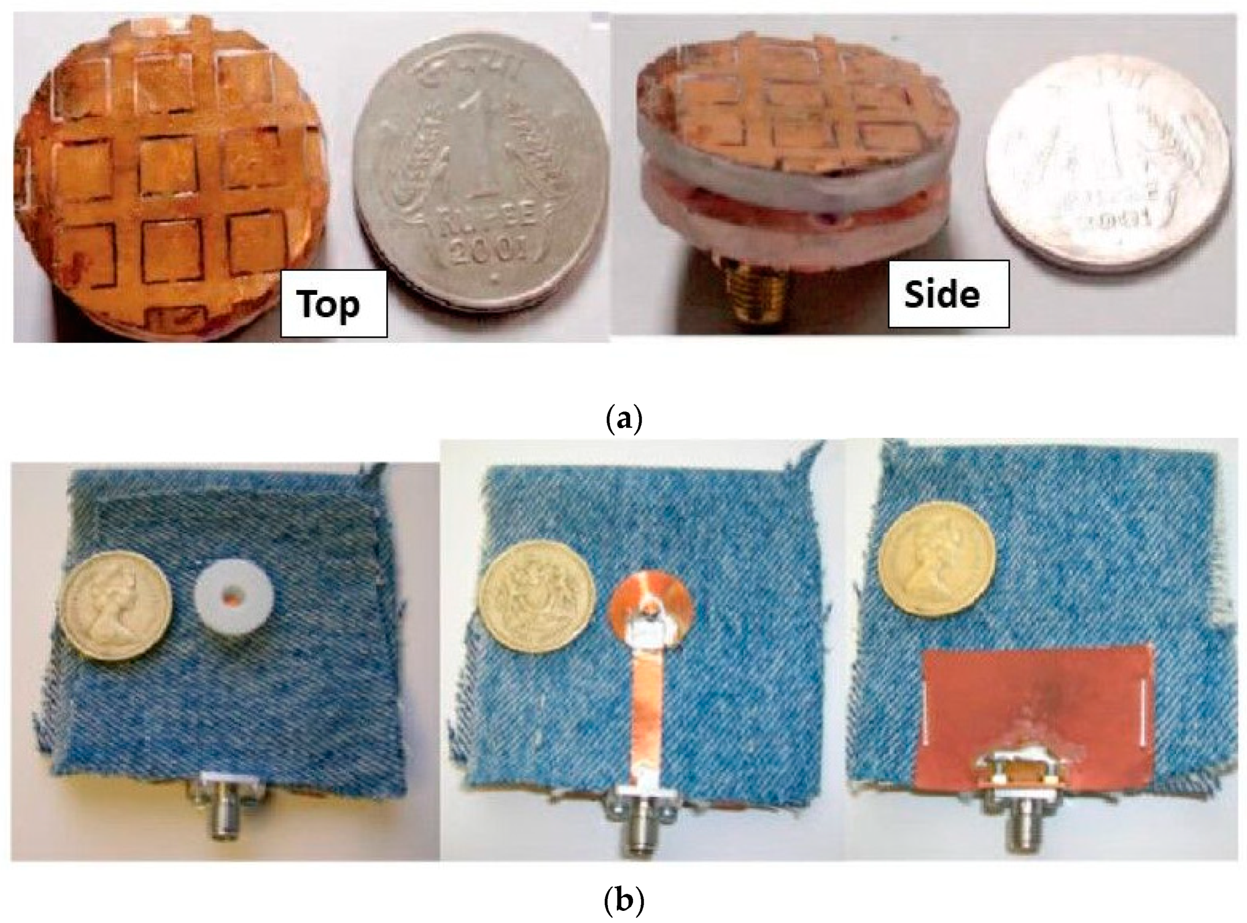
2.1.1. Buttons
2.1.2. Snap-On Buttons
2.2. Velcro
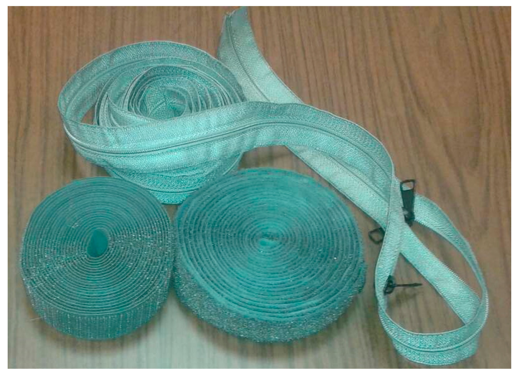
2.3. Zip
2.4. Discussion on Research Data of Wearable Textile Antennas Characteristics and Performance
3. Design Procedure
- (a)
- Concept selection
- (b)
- Materials definition and characterization
- (c)
- Reference antenna design
- (d)
- CC antenna initial design and modeling
- (e)
- Final CC antenna validation
- (a)
- Concept Selection
- (b)
- Materials definition and characterization
- (b1)
- Conductive cloth or yarn
- (b2)
- Dielectric substrate material
- (b3)
- Clothing component materials
- (c)
- Reference antenna design
- (d)
- CC antenna initial design and modeling
- (e)
- Final CC antenna validation
4. Experimental Evaluation
4.1. Wearable Textile Antenna Evaluation Scenarios
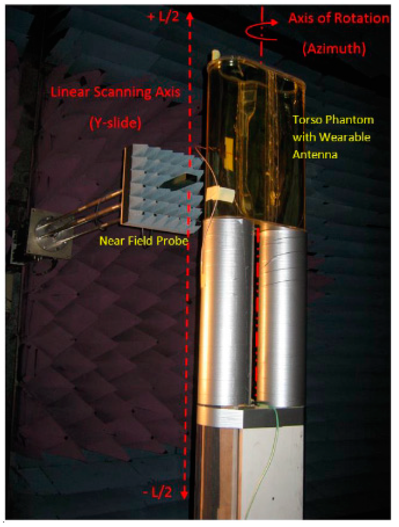
4.2. Measurements Techniques and Methods
4.3. Clothing Component Experimental Evaluation
5. Potentials of Textiles Technology in Wearable Antennas
6. Conclusions
Author Contributions
Funding
Informed Consent Statement
Data Availability Statement
Conflicts of Interest
References
- Corchia, L.; Monti, G.; Tarricone, L. Wearable Antennas: Nontextile Versus Fully Textile Solutions. IEEE Antennas Propag. Mag. 2019, 61, 71–83. [Google Scholar] [CrossRef]
- Nepa, P.; Rogier, H. Wearable Antennas for Off-Body Radio Links at VHF and UHF Bands: Challenges, the state of the art, and future trends below 1 GHz. IEEE Antennas Propag. Mag. 2015, 57, 30–52. [Google Scholar] [CrossRef] [Green Version]
- Ali, S.; Sovuthy, C.; Imran, M.; Socheatra, S.; Abbasi, Q.; Abidin, Z. Recent Advances of Wearable Antennas in Materials, Fabrication Methods, Designs, and Their Applications: State-of-the-Art. Micromachines 2020, 11, 888. [Google Scholar] [CrossRef]
- El Gharbi, M.; Fernández-García, R.; Ahyoud, S.; Gil, I. A review of flexible wearable antenna sensors: Design, fabrication methods, and applications. Materials 2020, 13, 3781. [Google Scholar] [CrossRef] [PubMed]
- Almohammed, B.; Ismail, A.; Sali, A. Electro-textile wearable antennas in wireless body area networks: Materials, antenna design, manufacturing techniques, and human body consideration—A review. Text. Res. J. 2021, 91, 646–663. [Google Scholar] [CrossRef]
- Krifa, M. Electrically Conductive Textile Materials—Application in Flexible Sensors and Antennas. Textiles 2021, 1, 239–257. [Google Scholar] [CrossRef]
- Tsolis, A.; Whittow, W.; Alexandridis, A.; Vardaxoglou, J. Embroidery and Related Manufacturing Techniques for Wearable Antennas: Challenges and Opportunities. Electronics 2014, 3, 314–338. [Google Scholar] [CrossRef] [Green Version]
- Mohamadzade, B.; Hashmi, R.M.; Simorangkir, R.B.V.B.; Gharaei, R.; Rehman, S.U.; Abbasi, Q.H. Recent advances in fabrication methods for flexible antennas in wearable devices: State of the art. Sensors 2019, 19, 2312. [Google Scholar] [CrossRef] [PubMed] [Green Version]
- Kirtania, S.G.; Elger, A.W.; Hasan, M.R.; Wisniewska, A.; Sekhar, K.; Karacolak, T.; Sekhar, P.K. Flexible antennas: A review. Micromachines 2020, 11, 847. [Google Scholar] [CrossRef] [PubMed]
- Farahiyah, N.; Aun, M.; Soh, P.J.; Vandenbosch, G.A.E.; Schreurs, D. Revolutionizing Wearables for 5G. IEEE Microw. Mag. 2017, 18, 108–124. [Google Scholar]
- Salman, L.K.H.; Talbi, L. G-shaped wearable cuff button antenna for 2.45 GHZ ISM band applications. In Proceedings of the 14th International Symposium on Antenna Technology and Applied Electromagnetics and the American Electromagnetics Conference (ANTEM/AMEREM), Ottawa, ON, Canada, 5–8 July 2010; pp. 14–17. [Google Scholar] [CrossRef]
- Sanz-Izquierdo, B.; Batchelor, J.C. Button Antennas for Wearable Applications. In Proceedings of the IET Seminar on Antennas and Propagation for Body-Centric Wireless Communications, London, UK, 24 April 2007; pp. 97–104. [Google Scholar] [CrossRef]
- Floc’h, J.M.; Queudet, F.; Fourn, E. Radio-electric characterizations of jeans buttons. In Proceedings of the 2nd European Conference on Antennas and Propagation (EuCAP), Edinburgh, UK, 11–16 November 2007; pp. 1–4. [Google Scholar] [CrossRef]
- Mandal, B.; Chatterjee, A.; Parui, S.K. A wearable button antenna with FSS superstrate for WLAN health care applications. In Proceedings of the IEEE MTT-S International Microwave Workshop Series on: RF and Wireless Technologies for Biomedical and Healthcare Applications, IMWS-Bio, London, UK, 8–10 December 2014; pp. 1–3. [Google Scholar] [CrossRef]
- Sanz-Izquierdo, B.; Huang, F.; Batchelor, J.C. Covert dual-band wearable button antenna. IET Electron. Lett. 2006, 42, 982–983. [Google Scholar] [CrossRef]
- Sanz-Izquierdo, B.; Huang, F.; Batchelor, J.C. Dual band button antennas for wearable applications. In Proceedings of the IEEE International Workshop on Antenna Technology, iWAT—Small Antennas and Novel Metamaterials, White Plains, NY, USA, 6–8 March 2006; pp. 132–135. [Google Scholar] [CrossRef]
- Sanz-Izquierdo, B.; Huang, F.; Batchelor, J.C.; Sobhy, M. Compact antenna for WLAN on body applications. In Proceedings of the 36th European Microwave Conference (EuMC), Manchester, UK, 10–15 September 2007; pp. 815–818. [Google Scholar] [CrossRef]
- Hu, X.; Yan, S.; Zhang, J.; Vandenbosch, G.A.E. Wearable Button Antenna for Dual-Band WLAN Applications with Combined on and off-Body Radiation Patterns. IEEE Trans. Antennas Propag. 2017, 65, 2191–2193. [Google Scholar] [CrossRef]
- Mo, T.; Lin, Q.W.; Zhang, X.Y.; Wong, H. A Dual Operating Mode Antenna on Flexible Ground Structures for Wearable Communications. In Proceedings of the International Applied Computational Electromagnetics Society Symposium (ACES), Firenze, Italy, 26–30 March 2017; pp. 1–2. [Google Scholar]
- Hu, X.; Yan, S.; Zhang, J.; Vandenbosch, G.A.E. Dual-band WLAN button antenna for both on and off-body applications. In Proceedings of the 11th European Conference on Antennas and Propagation (EuCAP), Paris, France, 19–24 March 2017; pp. 2191–2193. [Google Scholar] [CrossRef]
- Sanz-Izquierdo, B.; Huang, F.; Batchelor, J.C. Small size wearable button antenna. In Proceedings of the 1st European Conference on Antennas and Propagation (EuCAP), Nice, France, 6–10 November 2006; pp. 1–4. [Google Scholar] [CrossRef]
- Salman, L.K.H.; Talbi, L. Dual Band G-shape wearable cuff button antenna for ISM bands applications. In Proceedings of the EEE International Symposium on Antennas and Propagation and CNC-USNC/URSI Radio Science Meeting—Leading the Wave, AP-S/URSI, Toronto, ON, Canada, 11–17 July 2020; Volume 2, pp. 5–8. [Google Scholar] [CrossRef]
- Sanz-Izquierdo, B.; Miller, J.A.; Batchelor, J.C.; Sobhy, M.I. Dual-band wearable metallic button antennas and transmission in body area networks. IET Microw. Antennas Propag. 2010, 4, 182. [Google Scholar] [CrossRef]
- Sanz-Izquierdo, B.; Batchelor, J.C.; Sobhy, M.I. Button antenna on textiles for wireless local area network on body applications. IET Microw. Antennas Propag. 2010, 4, 1980. [Google Scholar] [CrossRef] [Green Version]
- Sanz-Izquierdo, B.; Batchelor, J.C. Wlan jacket mounted antenna. In Proceedings of the IEEE International Workshop on Antenna Technology: Small and Smart Antennas Metamaterials and Applications, iWAT, Cambridge, UK, 1–23 March 2007; pp. 57–60. [Google Scholar] [CrossRef]
- Zhang, X.Y.; Wong, H.; Mo, T.; Cao, Y.F. Dual-Band Dual-Mode Button Antenna for On-Body and Off-Body Communications. IEEE Trans. Biomed. Circuits Syst. 2017, 11, 933–941. [Google Scholar] [CrossRef] [PubMed]
- Yin, X.; Chen, S.J.; Fumeaux, C. Wearable Dual-Band Dual-Polarization Button Antenna for WBAN Applications. IEEE Antennas Wirel. Propag. Lett. 2020, 19, 2240–2244. [Google Scholar] [CrossRef]
- Zhang, J.; Yan, S.; Hu, X.; Vandenbosch, G.A.E. Dual-Band Dual-Polarized Wearable Button Array with Miniaturized Radiator. IEEE Trans. Biomed. Circuits Syst. 2019, 13, 1583–1592. [Google Scholar] [CrossRef]
- Yu, S.; Liu, Y.; Jiang, W.; Gong, S. A Novel Textile UWB Antenna. In Proceedings of the International Symposium on Antennas and Propagation (ISAP), Nagoya, Japan, 29 October–2 November 2012; pp. 1051–1054. [Google Scholar]
- Sanz-Izquierdo, B.; Batchelor, J.C.; Sobhy, M.I. Compact UWB wearable antenna. In Proceedings of the Loughborough Antennas and Propagation Conference (LAPC), Loughborough, UK, 2–3 April 2007; pp. 121–124. [Google Scholar] [CrossRef]
- Sanz-Izquierdo, B.; Batchelor, J.C.; Sobhy, M. UWB wearable button antenna. In Proceedings of the European Conference on Antennas & Propagation (EuCAP), Nice, France, 6–10 November 2006; pp. 9–12. [Google Scholar] [CrossRef]
- Le, T.T.; Kim, Y.D.; Yun, T.Y. Wearable Pattern-Diversity Dual-Polarized Button Antenna for Versatile On-/Off-Body Communications. IEEE Access 2022, 10, 98700–98711. [Google Scholar] [CrossRef]
- Saravanya, B. A miniaturized wearable button antenna for WiGig applications. In Proceedings of the 4th International Conference on Advanced Computing and Communication Systems (ICACCS), Coimbatore, India, 6–7 January 2017; pp. 7–10. [Google Scholar] [CrossRef]
- Karthikeya, G.S.; Devaiah, K.K.; Sharma, R.S.G.; Patel, M.H.B.; Mandi, N.R.; Thyagaraj, T. Wearable button antenna array for v band application. In Proceedings of the 5th Asia-Pacific Conference on Antennas and Propagation (APCAP), Kaohsiung, Taiwan, 26–29 July 2016; pp. 283–284. [Google Scholar] [CrossRef]
- Puskely, J.; Pokorny, M.; Lacik, J.; Raida, Z. Wearable Disc-Like Antenna for Body-Centric Communications at 61 GHz. IEEE Antennas Wirel. Propag. Lett. 2015, 14, 1490–1493. [Google Scholar] [CrossRef]
- Aldrigo, M.; Bianchini, D. New broadband button-shaped antenna on innovative magneto-dielectric material for wearable applications. In Proceedings of the 9th European Radar Conference (EuRC), Amsterdam, The Netherlands, 29 October–1 November 2012; pp. 397–400. [Google Scholar]
- Hu, X.; Yan, S.; Vandenbosch, G.A.E. Compact Circularly Polarized Wearable Button Antenna with Broadside Pattern for U-NII Worldwide Band Applications. IEEE Trans. Antennas Propag. 2019, 67, 1341–1345. [Google Scholar] [CrossRef]
- Hu, X.; Yan, S.; Zhang, J.; Volskiy, V.; Vandenbosch, G.A.E. Omni-Directional Circularly Polarized Button Antenna for 5 GHz WBAN Applications. IEEE Trans. Antennas Propag. 2021, 69, 5054–5059. [Google Scholar] [CrossRef]
- Chu, B.; Cheng, G.S. Design ofWideband Button Antenna Based on Characteristic Mode Theory. IEEE Trans. Bio-Med. Circuits Syst. 2018, 12, 1383–1391. [Google Scholar] [CrossRef]
- Chen, S.J.; Ranasinghe, D.C.; Fumeaux, C. A foldable textile patch for modular snap-on-button-based wearable antennas. In Proceedings of the URSI International Symposium on Electromagnetic Theory, (EMTS), Espoo, Finland, 14–18 August 2016; pp. 842–845. [Google Scholar] [CrossRef]
- Chen, S.J.; Kaufmann, T.; Ranasinghe, D.C.; Fumeaux, C. A Modular Textile Antenna Design Using Snap-on Buttons for Wearable Applications. IEEE Trans. Antennas Propag. 2016, 64, 894–903. [Google Scholar] [CrossRef] [Green Version]
- Chen, S.J.; Ranasinghe, D.C.; Fumeaux, C. A polarization/frequency interchangeable patch for a modular wearable textile antenna. In Proceedings of the 11th European Conference on Antennas and Propagation (EuCAP), Paris, France, 19–24 March 2017; pp. 2483–2486. [Google Scholar] [CrossRef]
- Chen, S.J.; Ranasinghe, D.C.; Fumeaux, C. Snap-on buttons as detachable shorting vias for wearable textile antennas. In Proceedings of the 18th International Conference on Electromagnetics in Advanced Applications (ICEAA), Cairns, QLD, Australia, 19–23 September 2016; pp. 521–524. [Google Scholar] [CrossRef]
- Chen, S.J.; Ranasinghe, D.C.; Fumeaux, C. A Robust Snap-On Button Solution for Reconfigurable Wearable Textile Antennas. IEEE Trans. Antennas Propag. 2018, 66, 4541–4551. [Google Scholar] [CrossRef]
- Dang, Q.H.; Chen, S.J.; Ranasinghe, D.C.; Fumeaux, C. A Frequency-Reconfigurable Wearable Textile Antenna with One-Octave Tuning Range. IEEE Trans. Antennas Propag. 2021, 69, 8080–8089. [Google Scholar] [CrossRef]
- Cui, J.; Liu, F.; Zhao, L.; Dou, W. Textile Fixed-Frequency Pattern-Reconfigurable Coupled-Mode Substrate-Integrated Cavity Antenna. IEEE Antennas Wirel. Propag. Lett. 2022, 21, 1916–1919. [Google Scholar] [CrossRef]
- Tsolis, A.; Alexandridis, A.A.; Lazarakis, F.; Michalopoulou, A.; Whittow, W.G.; Vardaxoglou, J.C. All-textile connector for a wearable patch antenna. In Proceedings of the Loughborough Antennas & Propagation Conference (LAPC), Loughborough, UK, 12–13 November 2018; pp. 1–6. [Google Scholar]
- Tsolis, A.; Michalopoulou, A.; Alexandridis, A.A. Use of conductive zip and Velcro as a polarisation reconfiguration means of a textile patch antenna. IET Microwaves, Antennas Propag. 2020, 14, 684–693. [Google Scholar] [CrossRef]
- Mantash, M.; Tarot, A.C.; Collardey, S.; Mahdjoubi, K. Wearable monopole zip antenna. Electron. Lett. 2011, 47, 1266. [Google Scholar] [CrossRef]
- Mantash, M.; Tarot, A.-C.; Collardey, S.; Mahdjoubi, K. Zip Based Monopole Antenna for Wearable Communication Systems. In Proceedings of the 6th European Conference on Antennas and Propagation (EuCAP), Rome, Italy, 11–15 April 2011; pp. 762–764. [Google Scholar]
- Li, G.; Huang, Y.; Gao, G.; Wei, X.; Tian, Z.; Bian, L.A. A Handbag Zipper Antenna for the Applications of Body-Centric Wireless Communications and Internet of Things. IEEE Trans. Antennas Propag. 2017, 65, 5137–5146. [Google Scholar] [CrossRef] [Green Version]
- Li, G.; Ma, C.; Shen, W.; Chen, P.; Feng, Y. A Metal Zipper Antenna for Application of Wearable System. In Proceedings of the 2020 IEEE 4th Information Technology, Networking, Electronic and Automation Control Conference (ITNEC), Chongqing, China, 24–26 February 2020; pp. 1590–1593. [Google Scholar] [CrossRef]
- Bakogianni, S.; Tsolis, A.; Alexandridis, A. Design of a Novel Reconfigurable Wearable Antenna Based on Textile Materials and Snap-on Buttons. In Proceedings of the MobiHealth, online, 30 November–2 December 2022; pp. 1–10. [Google Scholar]
- Song, L.; Zhang, B.; Zhang, D.; Rahmat-Samii, Y. Embroidery Electro-Textile Patch Antenna Modeling and Optimization Strategies with Improved Accuracy and Efficiency. IEEE Trans. Antennas Propag. 2022, 70, 6388–6400. [Google Scholar] [CrossRef]
- Angelaki, C.; Bakogianni, S.; Tsolis, A.; Alexandridis, A.A. Embroidered Textile Patch Antennas: Design and Implementation Methodology. In Proceedings of the 30th Telecommunications Forum, TELFOR 2022—Proceedings, Belgrade, Serbia, 15–16 November 2022; pp. 9–12. [Google Scholar] [CrossRef]
- Yamada, Y. Dielectric Properties of Textile Materials: Analytical Approximations and Experimental Measurements—A Review. Textiles 2022, 2, 50–80. [Google Scholar] [CrossRef]
- QWED Company Homepage. Available online: https://www.qwed.com.pl/ (accessed on 2 March 2023).
- Balanis, A.C. Antenna Theory Analysis and Design, 3rd ed.; John Wiley Sons: Hoboken, NJ, USA, 2005. [Google Scholar]
- Moradi, E.; Björninen, T.; Ukkonen, L.; Rahmat-samii, Y. Characterization of Embroidered Dipole-type RFID Tag Antennas. In Proceedings of the IEEE International Conference on RFID-Technologies and Applications (RFID-TA), Nice, France, 5–7 November 2012; pp. 248–253. [Google Scholar]
- Osman, M.A.R.; Rahim, M.K.A.; Ali, M.F.; Samsuri, N.A.; Kamarudin, K. Design, Implementation and Performance of Ultra-Wideband Textile Antenna. Prog. Electromagn. Res. B 2011, 27, 307–325. [Google Scholar] [CrossRef] [Green Version]
- Gupta, B.; Sankaralingam, S.; Dhar, S. Development of Wearable and Implantable Antennas in the Last Decade: A review. In Proceedings of the Microwave Mediterranean Symposium (MMS), Guzelyurt, Northern Cyprus, 25–27 August 2010; pp. 251–267. [Google Scholar]
- Kim, S.; Lee, S.; Kwon, K.; Park, H.; Choi, J. Miniaturized and High-Isolation Diversity Antenna for WBAN Applications. In Proceedings of the ISAP, Nagoya, Japan, 29 October–2 November 2012; pp. 979–982. [Google Scholar]
- Salonen, P.; Rahmat-Samii, Y. Textile Antennas: Effects of Antenna Bending on Input Matching and Impedance Bandwidth. IEEE Aerosp. Electron. Syst. Mag. 2007, 22, 10–14. [Google Scholar] [CrossRef]
- Boeykens, F.; Vallozzi, L.; Rogier, H. Cylindrical Bending of Deformable Textile Rectangular Patch Antennas. Int. J. Antennas Propag. 2012, 2012, 170420. [Google Scholar] [CrossRef] [Green Version]
- Shimasaki, H.; Tanaka, M. Measurement of the Roundly Bending Characteistics of a Cavity Slot Antenna Made of Conductive Textile. In Proceedings of the Asia-Pacific Conference, Melbourne, VIC, Australia, 5–8 December 2011; pp. 1598–1601. [Google Scholar]
- Tanaka, J.; Jang, J.-H. Wearable microstrip antenna for Satellite Communications. In Proceedings of the 21st International Communications Satellite Systems Conference and Exhibit, Columbus, OH, USA, 22–27 June 2003; pp. 704–707. [Google Scholar] [CrossRef]
- Bai, Q.; Langley, R. Crumpling of PIFA Textile Antenna. IEEE Trans. Antennas Propag. 2012, 60, 63–70. [Google Scholar] [CrossRef]
- Bai, Q.; Langley, R. Crumpled textile antennas. Electron. Lett. 2009, 45, 436–438. [Google Scholar] [CrossRef] [Green Version]
- Lilja, J.; Salonen, P.; Kaija, T.; de Maagt, P. Design and Manufacturing of Robust Textile Antennas for Harsh Environments. IEEE Trans. Antennas Propag. 2012, 60, 4130–4140. [Google Scholar] [CrossRef]
- Hertleer, C.; Van Laere, A.; Rogier, H.; Van Langenhove, L. Influence of Relative Humidity on Textile Antenna Performance. Text. Res. J. 2009, 80, 177–183. [Google Scholar] [CrossRef]
- Koski, K.; Moradi, E.; Babar, A.A.; Björninen, T.; Sydänheimo, L.; Ukkonen, L. Durability of Embroidered Antennas in Wireless Body-Centric Healthcare Applications. In Proceedings of the 7th European Conference on Antennas and Propagation (EuCAP), Gothenburg, Sweden, 8–12 April 2013; pp. 565–569. [Google Scholar]
- Vallozzi, L.; Van Torre, P.; Hertleer, C.; Rogier, H.; Moeneclaey, M.; Verhaevert, J. Wireless communication for firefighters using dual-polarized textile antennas integrated in their garment. IEEE Trans. Antennas Propag. 2010, 58, 1357–1368. [Google Scholar] [CrossRef] [Green Version]
- Paul, D.L.; Giddens, H.; Paterson, M.G.; Hilton, G.S.; McGeehan, J.P. Impact of body and clothing on a wearable textile dual band antenna at digital television and wireless communications bands. IEEE Trans. Antennas Propag. 2013, 61, 2188–2194. [Google Scholar] [CrossRef]
- Zhang, S.; Chauraya, A.; Whittow, W.; Seager, R.; Acti, T.; Dias, T.; Vardaxoglou, Y. Repeatability of Embroidered Patch Antennas. In Proceedings of the Loughborough Antennas & Propagation Conference, Loughborough, UK, 11–12 November 2013; pp. 140–144. [Google Scholar]
- Koski, K.; Koski, E.; Björninen, T.; Babar, A.; Ukkonen, L.; Sydänheimo, L. Practical Read Range Evaluation of Wearable Embroidered UHF RFID Tag. In Proceedings of the Antennas and Propagation Society International Symposium (APS-URSI), Chicago, IL, USA, 8–14 July 2012; pp. 1–2. [Google Scholar]
- Boyes, S.J.; Soh, P.J.; Huang, Y.; Vandenbosch, G.A.E.; Khiabani, N. Measurement and Performance of Textile Antenna Efficiency on a Human Body in a Reverberation Chamber. IEEE Trans. Antennas Propag. 2013, 61, 871–881. [Google Scholar] [CrossRef] [Green Version]
- Psychoudakis, D.; Lee, G.; Chen, C.; Volakis, J.L. Military UHF Body-Worn Antennas for Armored Vests. In Proceedings of the European Conference on Antennas and Propagation (EuCAP), Barcelona, Spain, 12–16 April 2010; pp. 1–4. [Google Scholar]
- Zhang, L.; Wang, Z.; Psychoudakis, D.; Volakis, J.L. E-fiber Electronics for Body-Worn Devices. In Proceedings of the 6th European Conference on Antennas and Propagation (EuCAP), Rome, Italy, 11–15 April 2011; pp. 760–761. [Google Scholar]
- Santas, J.G.; Alomainy, A. Textile antennas for on-body communications: Techniques and properties. In Proceedings of the Second European Conference on Antennas and Propagation (EuCAP), Edinburgh, UK, 11–16 November 2007; p. 537. [Google Scholar] [CrossRef]
- Hasani, M.; Vena, A.; Sydänheimo, L.; Ukkonen, L.; Tentzeris, M.M. Implementation of a Dual-Interrogation-Mode Embroidered RFID-Enabled Strain Sensor. IEEE Antennas Wirel. Propag. Lett. 2013, 12, 1272–1275. [Google Scholar] [CrossRef]
- Raad, H.R.; Abbosh, A.I.; Al-rizzo, H.M.; Rucker, D.G. Flexible and Compact AMC Based Antenna for Telemedicine Applications. IEEE Trans. Antennas Propag. 2013, 61, 524–531. [Google Scholar] [CrossRef]
- Loh, T.H.; Cheadle, D.; Rosenfeld, L. Radiation pattern measurement of a low-profile wearable antenna using an optical fibre and a solid anthropomorphic phantom. Electronics 2014, 3, 462–473. [Google Scholar] [CrossRef] [Green Version]
- Tareq, S.; Hall, P.S. Efficiency Measuremnt of Antennas for On-Body Communications. Microw. Opt. Technol. Lett. 2006, 48, 2611–2615. [Google Scholar] [CrossRef]
- Hao, Y. Antennas and Propagation for Body Centric Wireless Communications in Healthcare. In Proceedings of the 2006 First European Conference on Antennas and Propagation, Nice, France, 6–10 November 2006. [Google Scholar]
- Psychoudakis, D.; Volakis, J.L.; Chen, C. Optimizing Wearable UHF Antennas for On-Body Operation. In Proceedings of the International Symposium on Antennas and Propagation, Honolulu, HI, USA, 9–15 June 2007; pp. 4184–4187. [Google Scholar]
- Chandra, R.; Johansson, A.J. An Analytical Link Loss Model for On-Body Propagation Around the Body Based on Elliptical Approximation of the Torso with Arms’ Influence Included. Antennas Wirel. Propag. Lett. IEEE 2013, 12, 528–531. [Google Scholar] [CrossRef] [Green Version]
- Nurul, H.M.R.; Malek, F.; Soh, P.J.; E Vandenbosch, G.A.; Volski, V.; Ooi, S.L.; Adam, I. Evaluation of a wearable hybrid textile antenna. In Proceedings of the Loughborough Antennas and Propagation Conference (LAPC), Loughborough, UK, 8–9 November 2010; pp. 337–340. [Google Scholar] [CrossRef]
- Chandra, R.; Johansson, A.J. An Elliptical Analytic Link Loss Model for Wireless Propagation Around the Human Torso. In Proceedings of the 6th European Conference on Antennas and Propagation (EuCAP), Prague, Czech Republic, 26–30 March 2011; pp. 3121–3124. [Google Scholar]
- Lin, C.H.; Ito, K. Compact wearable dual-mode antennas for body-centric wireless communications. In Proceedings of the IEEE Antennas and Propagation Society, AP-S International Symposium (Digest), Memphis, TN, USA, 6–11 July 2014; pp. 307–308. [Google Scholar] [CrossRef]
- Lin, C.-H.; Li, Z.; Ito, K.; Takahashi, M.; Saito, K. Dual-mode antenna for on-/off-body communications (10 MHz/2.45 GHz). Electron. Lett. 2012, 48, 1383–1384. [Google Scholar] [CrossRef]
- Kennedy, T.F.; Fink, P.W.; Chu, A.W.; Champagne, N.J.; Lin, G.Y.; Khayat, M.A. Body-Worn E-Textile Antennas: The Good, the Low-Mass, and the Conformal. IEEE Trans. Antennas Propag. 2009, 57, 910–918. [Google Scholar] [CrossRef]
- Park, J.; Woo, J. Miniaturization of microstrip line monopole antenna for the wearable applications. In Proceedings of the 2008 Asia-Pacific Microwave Conference, Hong Kong, China, 16–20 December 2008; pp. 1–4. [Google Scholar] [CrossRef]
- Soh, P.J.; Vandenbosch, G.A.E.; Higuera-oro, J. Design and Evaluation of Flexible CPW-fed UltraWide Band (UWB) Textile Antennas. In Proceedings of the IEEE International RF and Microwave Conference (RFM 2011), Seremban, Malaysia, 12–14 December 2011; pp. 133–136. [Google Scholar]
- Kellomaki, T.; Heikkinen, J.; Kivikoski, M. Wearable antennas for FM reception. In Proceedings of the First European Conference on Antennas and Propagation (EuCAP), Nice, France, 6–10 November 2006; pp. 1–6. [Google Scholar] [CrossRef]
- Kuramoto, A.; Furuya, K. Wideband Wearable Antenna. In Proceedings of the ISAP, Nigata, Japan, 20–24 August 2007; pp. 1086–1089. [Google Scholar]
- Roh, J.-S.; Chi, Y.-S.; Lee, J.-H.; Tak, Y.; Nam, S.; Kang, T.J. Embroidered Wearable Multiresonant Folded Dipole Antenna for FM Reception. IEEE Antennas Wirel. Propag. Lett. 2010, 9, 803–806. [Google Scholar] [CrossRef]
- Jalil, M.E.; Rahim, M.K.A.; Samsuri, N.A.; Ayop, O.; Abdullah, M.A.; Ismail, M.F. Investigation the performance of Koch fractal multiband textile antenna for on-body measurement. In Proceedings of the Asia-Pacific Microwave Conference Proceedings, APMC, Kaohsiung, Taiwan, 4–7 December 2012; pp. 1373–1375. [Google Scholar] [CrossRef]
- Tsolis, A.; Paraskevopoulos, A.; Alexandridis, A.A.; Whittow, W.G.; Chauraya, A.; Vardaxoglou, C. Design, realisation and evaluation of a liquid hollow torso phantom appropriate for wearable antenna assessment. IET Microw. Antennas Propag. 2017, 11, 1308–1316. [Google Scholar] [CrossRef] [Green Version]
- Balanis, C.A. Modern Antenna Handbook, 1st ed.; John and Wiley and Sons: New York, NY, USA, 2008. [Google Scholar]
- Wang, Z.; Zhang, L.; Psychoudakis, D.; Volakis, J.L. Flexible textile antennas for body-worn communication. In Proceedings of the IEEE International Workshop on Antenna Technology (iWAT), Tucson, AZ, USA, 5–7 March 2012; Volume 4, pp. 205–208. [Google Scholar] [CrossRef]
- Matthews, J.C.G.; Pettitt, G. Development of Flexible, Wearable Antennas. In Proceedings of the 3rd European Conference on Antennas and Propagation (EuCAP), Berlin, Germany, 23–27 March 2009; pp. 273–277. [Google Scholar]
- Loader, B.; Bownds, D.; Gregory, A. Assessing the Isotropy of Personal Electromagnetic Field Monitors. In Proceedings of the 7th International Workshop on Biological Effects of Electromagnetic Fields, Valleta, Malta, 8–12 October 2012; pp. 1–4. [Google Scholar]
- Bai, Q.; Swaisaenyakorn, S.; Lee, H.-J.; Ford, K.; Batchelor, J.; Langley, R. Investigation of a Switchable Textile Communication System on the Human Body. Electronics 2014, 3, 491–503. [Google Scholar] [CrossRef] [Green Version]
- Boyes, S.J.; Huang, Y.; Khiabani, N.; Soh, P.J.; Vandenbosch, G.A.E. Repeatability and uncertainty evaluations of on-body textile antenna efficiency measurements in a Reverberation Chamber. In Proceedings of the Loughborough Antennas and Propagation (LAPC), Loughborough, UK, 12–13 November 2012; pp. 1–5. [Google Scholar] [CrossRef]
- Soh, P.J.; Vandenbosch, G.A.E.; Chen, X.; Kildal, P.S.; Ooi, S.L.; Aliakbarian, H. Wearable textile antennas’ efficiency characterization using a reverberation chamber. In Proceedings of the IEEE Antennas and Propagation Society, AP-S International Symposium (Digest), Spokane, WA, USA, 3–8 July 2011; Volume 0603, pp. 810–813. [Google Scholar] [CrossRef] [Green Version]
- Conway, G.A.; Scanlon, W.G.; Orlenius, C.; Walker, C. In situ measurement of UHF wearable antenna radiation efficiency using a reverberation chamber. IEEE Antennas Wirel. Propag. Lett. 2008, 7, 271–274. [Google Scholar] [CrossRef]
- Gareth, A.C.; Scanlon, W.G.; Nunn, C.; Burdett, A. Layered RF Phantom Characterization for Wireless Medical Vital Sign Monitors. In Proceedings of the 2013 IEEE Antennas and Propagation Society International Symposium (APSURSI), Orlando, FL, USA, 7–13 July 2013; pp. 2201–2202. [Google Scholar] [CrossRef]
- Alomainy, A.; Loh, T.H. Experimental evaluation of wearable antenna efficiency for applications in body-centric wireless networks. In Proceedings of the IEEE MTT-S International Microwave Workshop Series on: RF and Wireless Technologies for Biomedical and Healthcare Applications, IMWS-Bio, London, UK, 8–10 December 2014; pp. 1–3. [Google Scholar] [CrossRef]
- Iversen, P.O.; Garreau, P.; Burrell, D. Real-time spherical near-field handset antenna measurements. IEEE Antennas Propag. Mag. 2001, 43, 90–94. [Google Scholar] [CrossRef]
- Krogerus, J.; Toivanen, J.; Icheln, C.; Vainikainen, P. Effect of the human body on total radiated power and the 3-D radiation pattern of mobile handsets. IEEE Trans. Instrum. Meas. 2007, 56, 2375–2385. [Google Scholar] [CrossRef]
- Conway, G.A.; Scanlon, W.G. Antennas for Over-Body-Surface Communication at 2.45 GHz. IEEE Trans. Antennas Propag. 2009, 57, 844–855. [Google Scholar] [CrossRef]
- Guraliuc, A.R.; Chahat, N.; Leduc, C.; Zhadobov, M.; Sauleau, R. End-fire antenna for BAN at 60 GHz: Impact of bending, on-body performances, and study of an on to off-body scenario. Electronics 2014, 3, 221–233. [Google Scholar] [CrossRef]
- Matthews, J.C.G.; Pirollo, B.; Tyler, A.; Pettitt, G. Body Wearable Antennas for Uhf/Vhf West. In Proceedings of the Loughborough Antennas & Propagation Conference (LAPC), Loughborough, UK, 17–18 March 2008; pp. 357–360. [Google Scholar]
- Paraskevopoulos, A.; Tsolis, A.; Vardaxoglou, J.C.; Alexandridis, A.A. Cylindrical near-field assessment of wearable antennas for body-centric communications. IET Microw. Antennas Propag. 2017, 11, 761–769. [Google Scholar] [CrossRef]
- Pandey, U.; Singh, P.; Singh, R. Review on miniaturized flexible wearable antenna with SAR measurement for body area network. Mater. Today Proc. 2022, 66, 3667–3674. [Google Scholar] [CrossRef]
- C95.1 Edition-1999; IEEE Standard for Safety Levels with Respect to Human Exposure to Radio Frequency Electromagnetic Fields, 3 kHz to 300 GHz. IEEE: New York, NY, USA, 1999.
- C95.1-2005; IEEE Standard for Safety Levels with Respect to Human Exposure to Radio Frequency Electromagnetic Fields, 3 kHz to 300 GHz. IEEE: New York, NY, USA, 2006.
- Le, T.T.; Yun, T.-Y. Wearable Dual-Band High-Gain Low-SAR Antenna for Off-Body Communication. IEEE Antennas Propag. Mag. 2021, 20, 1175–1179. [Google Scholar] [CrossRef]
- Trajkovikj, J.; Skrivervik, A.K. Diminishing SAR for Wearable UHF Antennas. IEEE Antennas Wirel. Propag. Lett. 2015, 14, 1530–1533. [Google Scholar] [CrossRef]
- Seimeni, M.A.; Tsolis, A.; Alexandridis, A.A.; Pantelopoulos, S.A. The effects of ground-plane of a textile higher mode microstrip patch antenna on SAR. In Proceedings of the International Workshop on Antenna Technology, iWAT, Bucharest, Romania, 25–28 February 2020. [Google Scholar] [CrossRef]
- Gil, I.; Fernandez-Garcia, R. SAR impact evaluation on jeans wearable antennas. In Proceedings of the 11th European Conference on Antennas and Propagation, EUCAP, Paris, France, 19–24 March 2017; pp. 2187–2190. [Google Scholar] [CrossRef]
- Seimeni, M.A.; Tsolis, A.; Alexandridis, A.A.; Pantelopoulos, S.A. Human Exposure to EMFs from Wearable Textile Patch Antennas: Experimental Evaluation of the Ground-Plane Effect. Prog. Electromagn. Res. B 2021, 92, 71–89. [Google Scholar] [CrossRef]
- Saha, P.; Mitra, D.; Parui, S.K. Control of Gain and SAR for Wearable Antenna Using AMC Structure. Radioengineering 2021, 30, 81–88. [Google Scholar] [CrossRef]
- Ahmad, A.; Faisal, F.; Ullah, S.; Choi, D.Y. Design and SAR Analysis of a Dual Band Wearable Antenna for WLAN Applications. Appl. Sci. 2022, 12, 9218. [Google Scholar] [CrossRef]
- Trajkovikj, J.; Skrivervik, A.K. Comparison of SAR of UHF wearable antennas. In Proceedings of the 10th European Conference on Antennas and Propagation (EuCAP), Davos, Switzerland, 10–15 April 2016. [Google Scholar] [CrossRef]
- Wang, J.C.; Lim, E.G.; Leach, M.; Wang, Z.; Man, K.L. Review of SAR measurement methods in relation to wearable devices. Eng. Lett. 2016, 24, 256–262. [Google Scholar]
- Tsolis, A.; Alexandridis, A.; Lazarakis, F.; Whittow, W.; Vardaxoglou, Y.C. All-textile stripline for wearable applications: Practical interconnection implementation. In Proceedings of the European Conference on Antennas and Propagation (EuCAP), London, UK, 9–14 April 2018; pp. 10–12. [Google Scholar]


| Ref. | Type/Radiation | Dimensions (mm) L, W, H | App. | fc (GHz) | BW (GHz) | erad (%) | Gain (dBi) |
|---|---|---|---|---|---|---|---|
| [11] | Top Monopole/ Omnidirectional | 40, 40, 13.39 | ISM/Wi-Fi | 2.45 | 0.13 | N/A | N/A |
| [13] * | Top Monopole/ Omnidirectional | 17, 17, 15.35 | ISM | 4.5 | 0.65 | N/A | 2.2 |
| [14] | Triangle patch-FSS/ Broadside | 30, 30, 5 | WLAN | 5.25 | 0.6 | 70 | 5.1 |
| [15] | Disc Monopole/ Omnidirectional | 17, 17, 11 | WLAN | 2.4 5.2 | 0.147 1.404 | N/A | 2.4 |
| [16] | Disc Monopole/ Omnidirectional | 17, 17, 11 | WLAN | 2.4 5.35 | 0.147 1.404 | N/A | 2.4 |
| [17] | Disc Monopole/ Omnidirectional | 17, 17, 12.8 | WLAN | 2.4 5.25 | 0.159 1.605 | N/A | 0–3 |
| [18] | Patch/ Broadside | 16.02, 16.02, 4.575 | ISM/WLAN | 2.4 5.2 5.8 | 0.09 2.29 | 91.9 87.3 85.3 | 1.05 4.5 6.04 |
| [19] | E-shaped PIFA patch/ Omni-Broadside | N/A | ISM | 2.45 5.8 | 0.1 0.9 | Ν/A | −0.8 6.8 |
| [20] | Patch-Monopole/ Omni-Broadside | 16.02, 16.02, 4.575 | ISM | 2.4 5.2 5.5 | 0.09 2.29 | 91.6 87 85 | 1.05 3.4 6.08 |
| [21] | Disc Monopole/ Omnidirectional | 17, 17, 8.9 | WLAN | 2.45 525 | 0.294 1.82 | N/A | 2.2 3.6 |
| [22] | G-shaped Monοpole/ Omnidirectional | Complex Shape | ISM | 2.45 5.8 | 0.08 0.35 | N/A | N/A |
| [23] | Disc Monopole/ Omnidirectional | 16 (50 GND), 16 (50 GND), 13.1 | WLAN/ HiperLAN/2 | 2.45/5.2/5.5 | 0.1 1.44 | N/A | N/A |
| [24] | Disc Monopole/ Omnidirectional | 14.6 (60 GND), 14.6 (60 GND), 12.1 | WLAN | 2.4 5.5 | 0.165 1.15 | 89 85 | 2.65 5.1 |
| [25] | Disc Monopole/ Omnidirectional | 14.5, 14.5, 11.5 | Bluetooth/ WLAND | 2.45 5.25/5.5 | 0.3 2.3 | N/A | N/A |
| [26] | Top monopole spiral-like/ Omni-Broadside | Complex details inside multi-parametric | ISM/WLAN | 2.45 5.8 | 0.07 0.3 | 46.3 69.3 | −0.6 4.3 |
| [27] | Top monopole- Crossed-dipole/ Omni-Broadside | 18, 18, 10 | ISM/WBAN | 2.45 5.8 | 0.18 3.38 | N/A | 2.2 8.6 |
| [28] | Fractal/ Broadside | 19.5, 19.5, 18.5 | U-NII-5G/ WLAN | 4.55 5.2 | 0.11 0.2 | 85.5 92.5 | 7.45 7.5 |
| [29] | Top Monopole/ Omnidirectional | 24 (60 GND), 24 (60 GND),18.2 | UWB | 3.05–10.95 (4/6.5/9) | 7.9 | Ν/A | 3.45/5.1/5.6 |
| [30] | Circular Monοpole/ Omnidirectional | 15 (20.8 GND), 15 (36 GND), 9 | UWB | 3.1–10.6 (3.5/6/9) | >7.5 | N/A | 2.6/1.9/ 3.4 |
| [31] | Top Conical Monopole/ Omnidirectional | 26, 26, 12.5 | UWB | 3–12 (3.5/6/9) | 9 | N/A | 3.9/2.8/4 |
| [32] | Crossed-dipole- Annular ring/ Omni-Broadside | 41.4, 41.4, 15 | UWB ISM/WLAN/5G | 4.12–9.12 2.45/3.7/5.85 | 5 0.16/0.35/0.39 | >90 40–70 | 6–7.8 1/6.2/4.5 |
| [33] | Hexagonal Patch/ Broadside | 10, 8.66, N/A | WiGig/WBAN/Medical | 62.12 | 11.91 | N/A | 5 |
| [34] | Button Array (Disc Monopole)/Directive | 10, 10, 4.8 (Single element) | WiGig | 59 | 1.1 | N/A | 35 |
| [35] | Planar Disc Monopole Multi-Ring/ Multidirectional | 49.7, 31, 0.508 (substrate) | WiGig | 61 | 4.27 | 65 | 4.7 |
| [36] | Patch/ Broadside | 33, 33, 5 | ISM | 0.868 | 0.25 | 1.5 | −11.8 |
| [37] | Top-monopole-loop loaded/Broadside | 19.54 (100 GND), 19.5 (100 GND), 4.12 | U-NII | 5.5 | 0.68 | N/A | 3.8 |
| [38] | Magnetic dipole-patch loaded/ Omnidirectional | 19, 19, 10.29 | WBAN | 5.8 | 0.23 | 72.6 | 2.1 |
| [39] | Ring/Various | 15, 15, 10.087 | ISM/5G | 2.45 | 0.658 | 97 | 1.8 |
| Ref. | Type/ Radiation | Dimensions (mm) L, W, H | App. | fc (GHz) | BW (GHz) | erad (%) | Gain (dBi) |
|---|---|---|---|---|---|---|---|
| [40] | Patch/ Broadside | 15.2, 7.5, 3.5 (40 × 40 GND) | ISM, X-band | 8 | 0.6 | N/A | 9.2 |
| 13.4, 7.5, 3.5 (40 × 40 GND) | ISM, X-band | 9 | 0.8 | 9.3 | |||
| 11.8, 7.5, 3.5 (40 × 40 GND) | ISM, X-band | 10 | 1.4 | 9.2 | |||
| [41] | Various Patches/ Omni-Broadside | Complex details | ISM, WLAN | 5 (RHCP) | 0.55 | N/A | 5 |
| ISM, WLAN | 5 (LHCP) | 0.5 | 5 | ||||
| ISM, WLAN | 2.45 (LP-PIFA) | 0.1 | 3.5 | ||||
| ISM, WLAN | 5.3 (LP) | 0.3 | 7.8 | ||||
| ISM, WLAN | 4.72/5.1/5.26 (LP-SLOT) | 0.25–0.8 | N/A | ||||
| ISM, X-band | 8 (FOLDABLE) | 0.5 | 8.9 | ||||
| [42] | Circular Patch/ Broadside | 23.4, 23.4, 3.5 (40 × 40 GND) | ISM/WLAN | 5 (CP) 4.7 (Slot) 5.2 (No-Slot) | 0.5 0.6345 0.494 | N/A | N/A |
| [43] | Patch/ Broadside | 18.5, 19.5, 3.5 (40 × 40 GND) | ISM | 3.62 | 0.1 | N/A | N/A |
| [44] | PIFA or Patch/ Broadside | 23, 20, 3.2 (60 × 55 GND) | ISM/WLAN | 2.45 5.8 | 0.093 0.234 | 30–90.2 80.4–88.7 | −0.9–5.9 8.1–8.4 |
| [45] | PIFA/ Broadside | 26, 22, 3.2 (60 × 50 GND) | ISM | 1.82–2.94 | 0.071–0.153 | 29.8–93.7 | −1.07–7.37 |
| [46] | CMSIC/ Omni-broadside | 120, 79.7, 3.2 (120 × 120 GND) | ISM | 2.45 | N/A | OFF:82.7 ON:77.1 | OFF:9.2 ON:3.8 |
| Ref. | Type/ Radiation | Dimensions (mm) L, W, H | App. | fc (GHz) | BW (GHz) | erad (%) | Gain (dBi) |
|---|---|---|---|---|---|---|---|
| [47] | Patch/ Broadside | 49, 57.6, 4.26 (100 × 70 GND) | ISM/WLAN | 2.486 | 0.09 | 85.76 | 7.80 |
| [48] | Patch/ Broadside | 53, 53, 4.2 (100.4 × 74.2 GND) | ISM/WLAN | 2.47 (LP) 2.35 (CP) | 0.103 0.170 | 77.1 79.5 | 6.10 6.88 |
| Refs. | Type/ Radiation | Dimensions (mm) L, W, H | App. | fc (GHz) | BW (GHz) | erad (%) | Gain (dBi) |
|---|---|---|---|---|---|---|---|
| [48] | Patch/ Broadside | 53, 53, 4.2 (100.4 × 74.2 GND) | ISM/WLAN | 2.39 (LP) 2.31 (CP) | 0.113 0.142 | 62.3 60.2 | 4.97 5.67 |
| [49,50] | Zip monopole/ Omnidirectional | 57, 6, 2 (30 × 40 GND) | ISM/WLAN/ Bluetooth | 2.5 5.6 | 0.95 N/A | N/A | 0 |
| [51] | Zip monopole/ Various | 385, 13, 21.535 | ISM/WLAN/ Bluetooth/IoT | 2.2 2.44 2.53 | 0.12 | 98.4 99 98.4 | 4.72 4.74 5.79 |
| [52] | Zip monopole/ Various | Complex | ISM/WLAN/IoT | 2.4 5.5 | N/A | N/A | 7.01 7.68 |
| Direction | Samples | εr | tan δ |
|---|---|---|---|
| A | A1 | 1.404 | 0.0198 |
| A2 | 1.359 | 0.0184 | |
| A3 | 1.335 | 0.0173 | |
| B | B1 | 1.396 | 0.0187 |
| B2 | 1.377 | 0.0186 | |
| B3 | 1.376 | 0.0187 |
| Antenna | fc (GHz) | S11 (dB) | BW (MHz) | AR (dB) | erad (%) | Gain (dBi) | |
|---|---|---|---|---|---|---|---|
| REF1 | Simulations | 2.45 | −22 | 70 | 55 | 96 | 7.78 |
| Measurements | 2.47 | −35 | 79 | 18 | 94.7 | 6.90 | |
| REF2 | Simulations | 2.33 | −9.1 | 120 | 1.9 | 94.7 | 8.20 |
| Measurements | 2.34 | −10 | 160 | 3.1 | 94.7 | 7.44 |
| Antenna | fc (GHz) | S11 (dB) | BW (MHz) | erad (%) | Gain (dBi) |
|---|---|---|---|---|---|
| REF (Pins) | 2.45 | −29.6 | 83.2 | 69.9 | 1.2 |
| CC (Snap-on buttons) | 2.446 | −29.5 | 83.6 | 69.1 | 1.1 |
Disclaimer/Publisher’s Note: The statements, opinions and data contained in all publications are solely those of the individual author(s) and contributor(s) and not of MDPI and/or the editor(s). MDPI and/or the editor(s) disclaim responsibility for any injury to people or property resulting from any ideas, methods, instructions or products referred to in the content. |
© 2023 by the authors. Licensee MDPI, Basel, Switzerland. This article is an open access article distributed under the terms and conditions of the Creative Commons Attribution (CC BY) license (https://creativecommons.org/licenses/by/4.0/).
Share and Cite
Tsolis, A.; Bakogianni, S.; Angelaki, C.; Alexandridis, A.A. A Review of Clothing Components in the Development of Wearable Textile Antennas: Design and Experimental Procedure. Sensors 2023, 23, 3289. https://doi.org/10.3390/s23063289
Tsolis A, Bakogianni S, Angelaki C, Alexandridis AA. A Review of Clothing Components in the Development of Wearable Textile Antennas: Design and Experimental Procedure. Sensors. 2023; 23(6):3289. https://doi.org/10.3390/s23063289
Chicago/Turabian StyleTsolis, Aris, Sofia Bakogianni, Chrysanthi Angelaki, and Antonis A. Alexandridis. 2023. "A Review of Clothing Components in the Development of Wearable Textile Antennas: Design and Experimental Procedure" Sensors 23, no. 6: 3289. https://doi.org/10.3390/s23063289