A Virtual Multi-Ocular 3D Reconstruction System Using a Galvanometer Scanner and a Camera
Abstract
:1. Introduction
2. Methodology
2.1. Configuration and Construction of the VMOS
2.2. Calibration Method of the VMOS
- For the calibration of the camera intrinsic parameters, among images with different index s and fixed index , match the 3D points with the image points . Take the matched pairs into Zhang’s monocular camera calibration process [28,31] for calibrating the intrinsic matrix in the pinhole camera model as shown in Equation (3) and the distortion parameters expressed in Equation (4).where is the homogeneous coordinates of the spatial point, is the ideal homogeneous pixel coordinates of the corresponding point, is the pose parameters of the camera, and is the depth coefficient.where and are the observed pixel coordinates with distortion corresponding to the ideal coordinates and , respectively; is the distance between the pixel point and the principle point of the pixel plane; , , and are the radial distortion parameters; and and are the tangential distortion parameters.
- For the calibration of the virtual camera poses, to calculate the sth virtual camera pose, gather the coded points in the images as a group with the same index and different index . Match the image points in each with according to index and . Utilizing the matched pairs in the specific group , the pose of the virtual camera , i.e., the transformation matrix from G-CS to the virtual camera coordinate system -CS, is calculated through the PnP method [29].
- For global optimization, to improve the calibration accuracy, the BA method [32] is applied to optimize the intrinsic parameters and all the virtual camera poses. In consideration of the lens distortion, we add radial distortion and tangential distortion to the BA model. The objective function of the nonlinear optimization iswhere is the reprojection pixel coordinates of spatial point in virtual camera calculated through Equations (3) and (4).
2.3. The 3D Reconstruction Method with the VMOS
2.4. Pose Estimation Method Using the VMOS
3. Experiments
3.1. Hardware Setup
3.2. Calibration Experiment
3.2.1. Galvanometer Repeatability Verification
3.2.2. VMOS Calibration
3.3. Experiments on 3D Coordinate Reconstruction
3.3.1. Reconstruction of a Visual Scale Bar
3.3.2. Reconstruction of Marker Points on 3D Structure
3.3.3. Repeatability of Reconstruction Verification
3.4. Experiment on Pose Estimation
4. Conclusions
Author Contributions
Funding
Institutional Review Board Statement
Informed Consent Statement
Data Availability Statement
Conflicts of Interest
References
- Fu, S.; Safaei, F.; Li, W. Optimization of camera arrangement using correspondence field to improve depth estimation. IEEE Trans. Image Process. 2017, 26, 3038–3050. [Google Scholar] [CrossRef] [PubMed]
- Shih, K.-T.; Chen, H.H. Generating high-resolution image and depth map using a camera array with mixed focal lengths. IEEE Trans. Comput. Imaging 2019, 5, 68–81. [Google Scholar] [CrossRef]
- Schonberger, J.L.; Frahm, J.-M. Structure-from-motion revisited. In Proceedings of the 2016 IEEE Conference on Computer Vision and Pattern Recognition (CVPR), Las Vegas, NV, USA, 26 June–1 July 2016; pp. 4104–4113. [Google Scholar]
- Gao, L.; Zhao, Y.; Han, J.; Liu, H. Research on multi-view 3D reconstruction technology based on SFM. Sensors 2022, 22, 4366. [Google Scholar] [CrossRef] [PubMed]
- Wang, P.; Zhang, L. Self-registration shape measurement based on fringe projection and structure from motion. Appl. Opt. 2020, 59, 10986. [Google Scholar] [CrossRef]
- Zhang, Z.Y.; Tsui, H.T. 3D reconstruction from a single view of an object and its image in a plane mirror. In Proceedings of the Fourteenth International Conference on Pattern Recognition (Cat. No.98EX170), Brisbane, QLD, Australia, 20 August 1998; Volume 2, pp. 1174–1176. [Google Scholar]
- Yu, L.; Pan, B. Single-camera stereo-digital image correlation with a four-mirror adapter: Optimized design and validation. Opt. Lasers Eng. 2016, 87, 120–128. [Google Scholar] [CrossRef]
- Radfar, E.; Jang, W.H.; Freidoony, L.; Park, J.; Kwon, K.; Jung, B. Single-channel stereoscopic video imaging modality based on transparent rotating deflector. Opt. Express 2015, 23, 27661–27671. [Google Scholar] [CrossRef]
- Jang, K.-W.; Yang, S.-P.; Baek, S.-H.; Lee, M.-S.; Park, H.-C.; Seo, Y.-H.; Kim, M.H.; Jeong, K.-H. Electrothermal MEMS parallel plate rotation for single-imager stereoscopic endoscopes. Opt. Express 2016, 24, 9667–9672. [Google Scholar] [CrossRef] [Green Version]
- Li, A.; Liu, X.; Zhao, Z. Compact three-dimensional computational imaging using a dynamic virtual camera. Opt. Lett. 2020, 45, 3801. [Google Scholar] [CrossRef]
- Liu, X.; Li, A. Multiview three-dimensional imaging using a Risley-prism-based spatially adaptive virtual camera field. Appl. Opt. 2022, 61, 3619. [Google Scholar] [CrossRef]
- Aylward, R.P. Advances and technologies of galvanometer-based optical scanners. In Proceedings of the Optical Scanning: Design and Application, SPIE, Denver, CO, USA, 2 July 1999; Volume 3787, pp. 158–164. [Google Scholar]
- Aylward, R.P. Advanced galvanometer-based optical scanner design. Sens. Rev. 2003, 23, 216–222. [Google Scholar] [CrossRef]
- Yin, Y.; Zhang, C.; Zhu, T. Penetration depth prediction of infinity shaped laser scanning welding based on latin hypercube sampling and the neuroevolution of augmenting topologies. Materials 2021, 14, 5984. [Google Scholar] [CrossRef] [PubMed]
- Yin, Y.; Zhang, C.; Zhu, T.; Qu, L.; Chen, G. Development of a laser scanning machining system supporting on-the-fly machining and laser power follow-up adjustment. Materials 2022, 15, 5479. [Google Scholar] [CrossRef] [PubMed]
- Mazzoli, A. Selective laser sintering in biomedical engineering. Med. Biol. Eng. Comput. 2013, 51, 245–256. [Google Scholar] [CrossRef] [PubMed]
- Alasil, T.; Waheed, N.K. Pan retinal photocoagulation for proliferative diabetic retinopathy: Pattern scan laser versus argon laser. Curr. Opin. Ophthalmol. 2014, 25, 164–170. [Google Scholar] [CrossRef]
- Tu, J.; Zhang, L. Rapid on-site recalibration for binocular vision galvanometric laser scanning system. Opt. Express 2018, 26, 32608–32623. [Google Scholar] [CrossRef]
- Tu, J.; Wang, M.; Zhang, L. A shortcut to marking 3D target curves on curved surface via a galvanometric laser scanner. Chin. J. Aeronaut. 2019, 32, 1555–1563. [Google Scholar] [CrossRef]
- Matsuka, D.; Mimura, M. Surveillance system for multiple moving objects. IEEJ J. Ind. Appl. 2020, 9, 460–467. [Google Scholar] [CrossRef]
- Aoyama, T.; Li, L.; Jiang, M.; Takaki, T.; Ishii, I.; Yang, H.; Umemoto, C.; Matsuda, H.; Chikaraishi, M.; Fujiwara, A. Vision-based modal analysis using multiple vibration distribution synthesis to inspect large-scale structures. J. Dyn. Syst. Meas. Control 2019, 141, 31007. [Google Scholar] [CrossRef]
- Okumura, K.; Ishii, M.; Tatsumi, E.; Oku, H.; Ishikawa, M. Gaze matching capturing for a high-speed flying object. In Proceedings of the SICE Annual Conference 2013, Nagoya, Japan, 14–17 September 2013; pp. 649–654. [Google Scholar]
- Hayakawa, T.; Watanabe, T.; Ishikawa, M. Real-time high-speed motion blur compensation system based on back-and-forth motion control of galvanometer mirror. Opt. Express 2015, 23, 31648. [Google Scholar] [CrossRef]
- Hayakawa, T.; Moko, Y.; Morishita, K.; Ishikawa, M. Pixel-wise deblurring imaging system based on active vision for structural health monitoring at a speed of 100 km/h. In Proceedings of the Tenth International Conference on Machine Vision (ICMV 2017), Vienna, Austria, 13–15 November 2017; Zhou, J., Radeva, P., Nikolaev, D., Verikas, A., Eds.; SPIE: Vienna, Austria, 2018; p. 26. [Google Scholar]
- Han, Z.; Zhang, L. Modeling and calibration of a galvanometer-camera imaging system. IEEE Trans. Instrum. Meas. 2022, 71, 5016809. [Google Scholar] [CrossRef]
- Hegna, T.; Pettersson, H.; Laundal, K.M.; Grujic, K. 3D laser scanner system based on a galvanometer scan head for high temperature applications. In Proceedings of the Optical Measurement Systems for Industrial Inspection VII, SPIE, Munich, Germany, 27 May 2011; Volume 8082, pp. 1195–1203. [Google Scholar]
- Shi, S.; Wang, L.; Johnston, M.; Rahman, A.U.; Singh, G.; Wang, Y.; Chiang, P.Y. Pathway to a compact, fast, and low-cost LiDAR. In Proceedings of the 2018 4th International Conference on Control, Automation and Robotics (ICCAR), Auckland, New Zealand, 20–23 April 2018; pp. 232–236. [Google Scholar]
- Zhang, Z. Flexible camera calibration by viewing a plane from unknown orientations. In Proceedings of the Seventh IEEE International Conference on Computer Vision, Kerkyra, Greece, 20–27 September 1999; Volume 1, pp. 666–673. [Google Scholar]
- Lepetit, V.; Moreno-Noguer, F.; Fua, P. EPnP: An accurate O(n) solution to the PnP problem. Int. J. Comput. Vis. 2009, 81, 155–166. [Google Scholar] [CrossRef] [Green Version]
- Hartley, R.; Zisserman, A. Multiple View Geometry in Computer Vision; Cambridge University Press: Cambridge, UK, 2003; ISBN 978-0-521-54051-3. [Google Scholar]
- Zhang, Z. A flexible new technique for camera calibration. IEEE Trans. Pattern Anal. Mach. Intell. 2000, 22, 1330–1334. [Google Scholar] [CrossRef] [Green Version]
- Li, Y.; Fan, S.; Sun, Y.; Wang, Q.; Sun, S. Bundle adjustment method using sparse BFGS solution. Remote Sens. Lett. 2018, 9, 789–798. [Google Scholar] [CrossRef]
- Quan, L.; Lan, Z. Linear N-point camera pose determination. IEEE Trans. Pattern Anal. Mach. Intell. 1999, 21, 774–780. [Google Scholar] [CrossRef] [Green Version]
- Gao, X.S.; Hou, X.R.; Tang, J.; Cheng, H.F. Complete solution classification for the perspective-three-point problem. IEEE Trans. Pattern Anal. Mach. Intell. 2003, 25, 930–943. [Google Scholar] [CrossRef]
- Fusiello, A.; Crosilla, F.; Malapelle, F. Procrustean point-line registration and the NPnP problem. In Proceedings of the 2015 International Conference on 3D Vision, Lyon, France, 19–22 October 2015; pp. 250–255. [Google Scholar]
- Yu, Z.J.; Shi, J. Decoding of dot-distribution coded targets and EO device. Appl. Mech. Mater. 2011, 58–60, 1246–1251. [Google Scholar] [CrossRef]
- Liu, X.; Li, A. An integrated calibration technique for variable-boresight three-dimensional imaging system. Opt. Lasers Eng. 2022, 153, 107005. [Google Scholar] [CrossRef]
- Terzakis, G.; Lourakis, M. A consistently fast and globally optimal solution to the perspective-n-point problem. In Proceedings of the Computer Vision—ECCV 2020, Glasgow, UK, 23–28 August 2020; Vedaldi, A., Bischof, H., Brox, T., Frahm, J.-M., Eds.; Springer International Publishing: Cham, Switzerland, 2020; pp. 478–494. [Google Scholar]

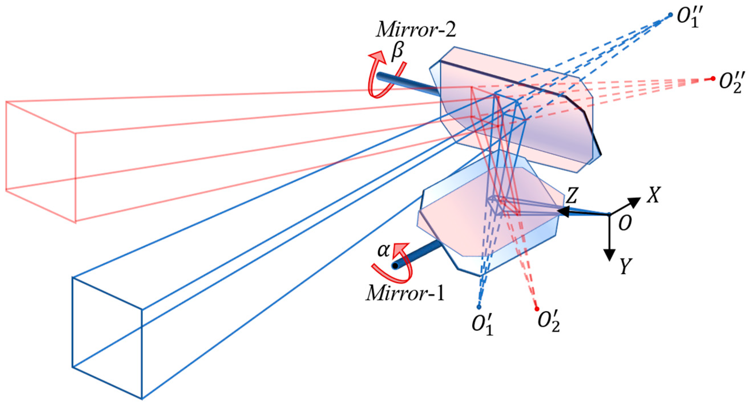
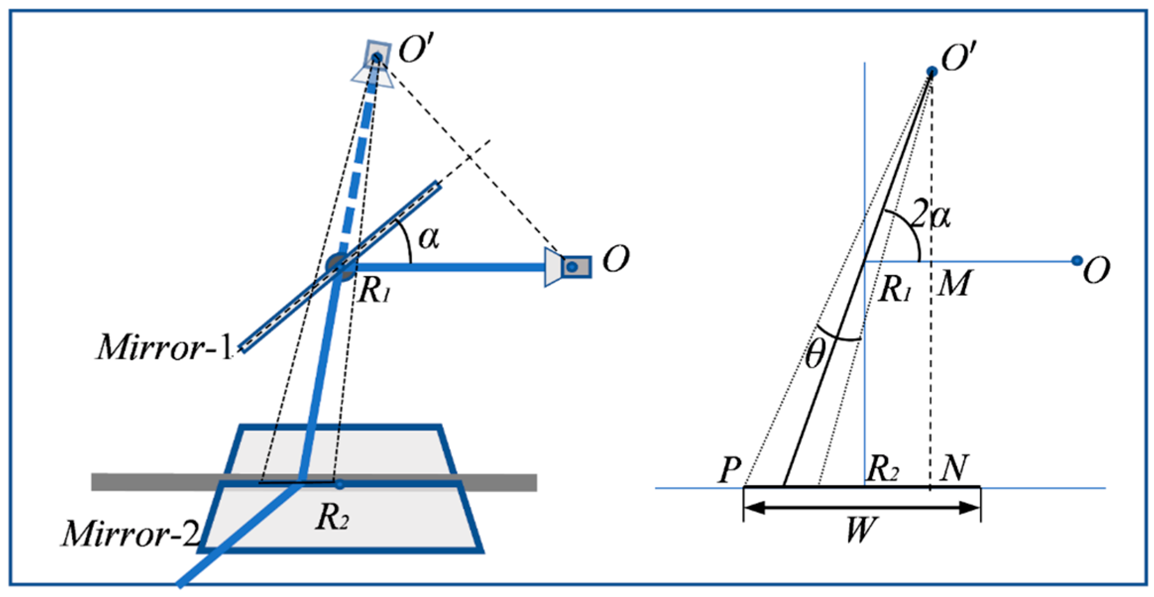
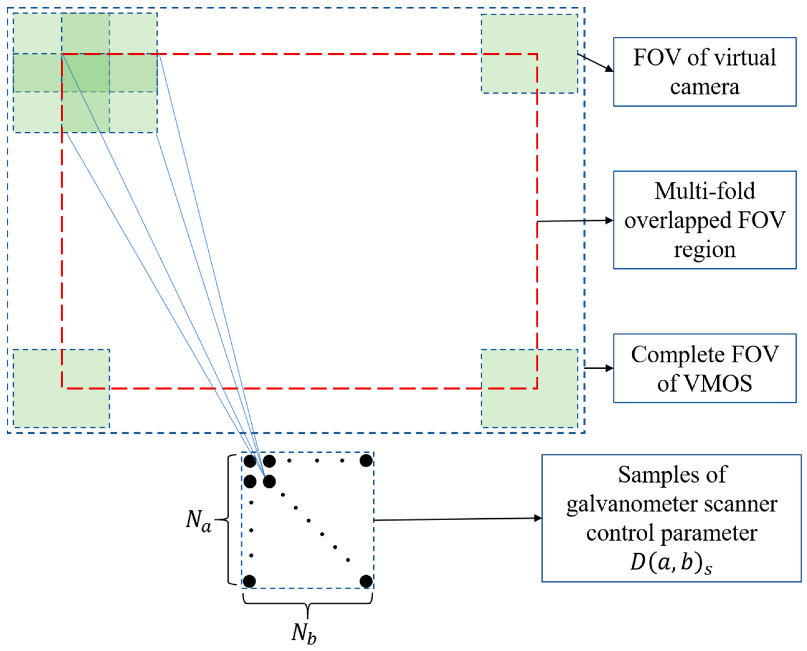

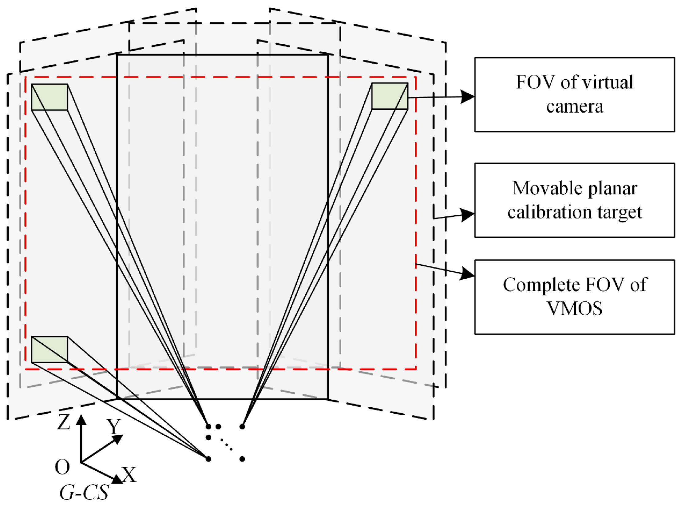
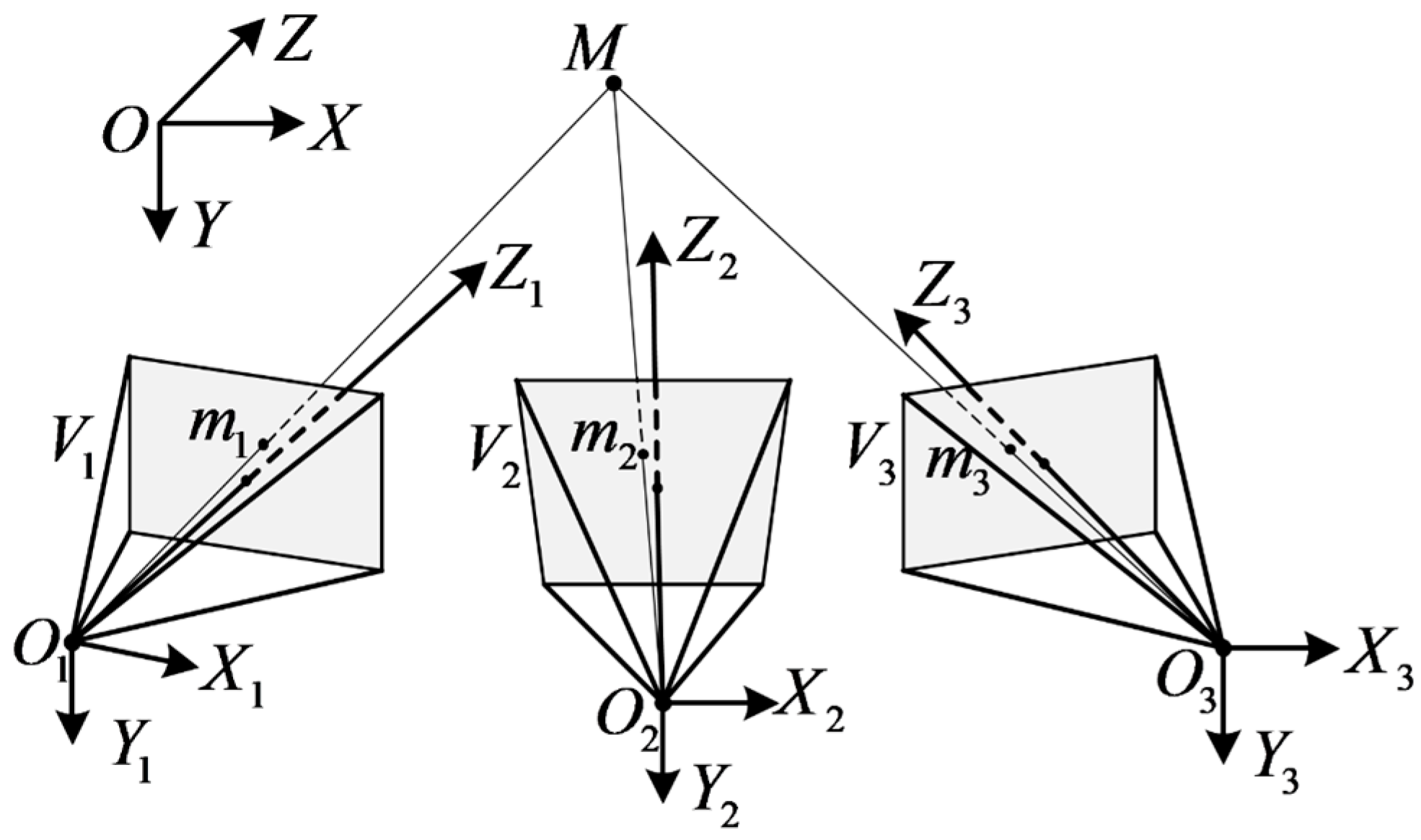

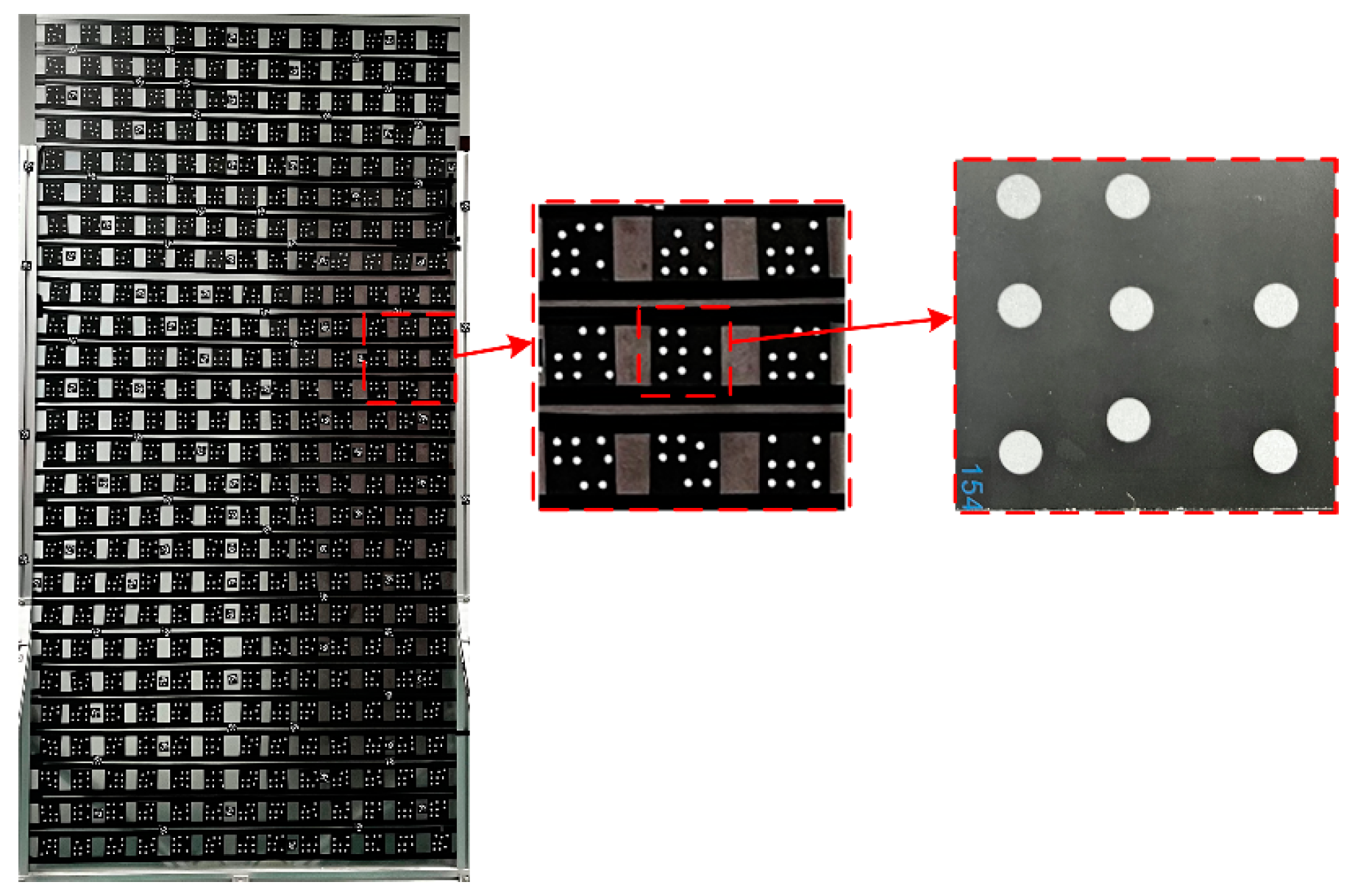

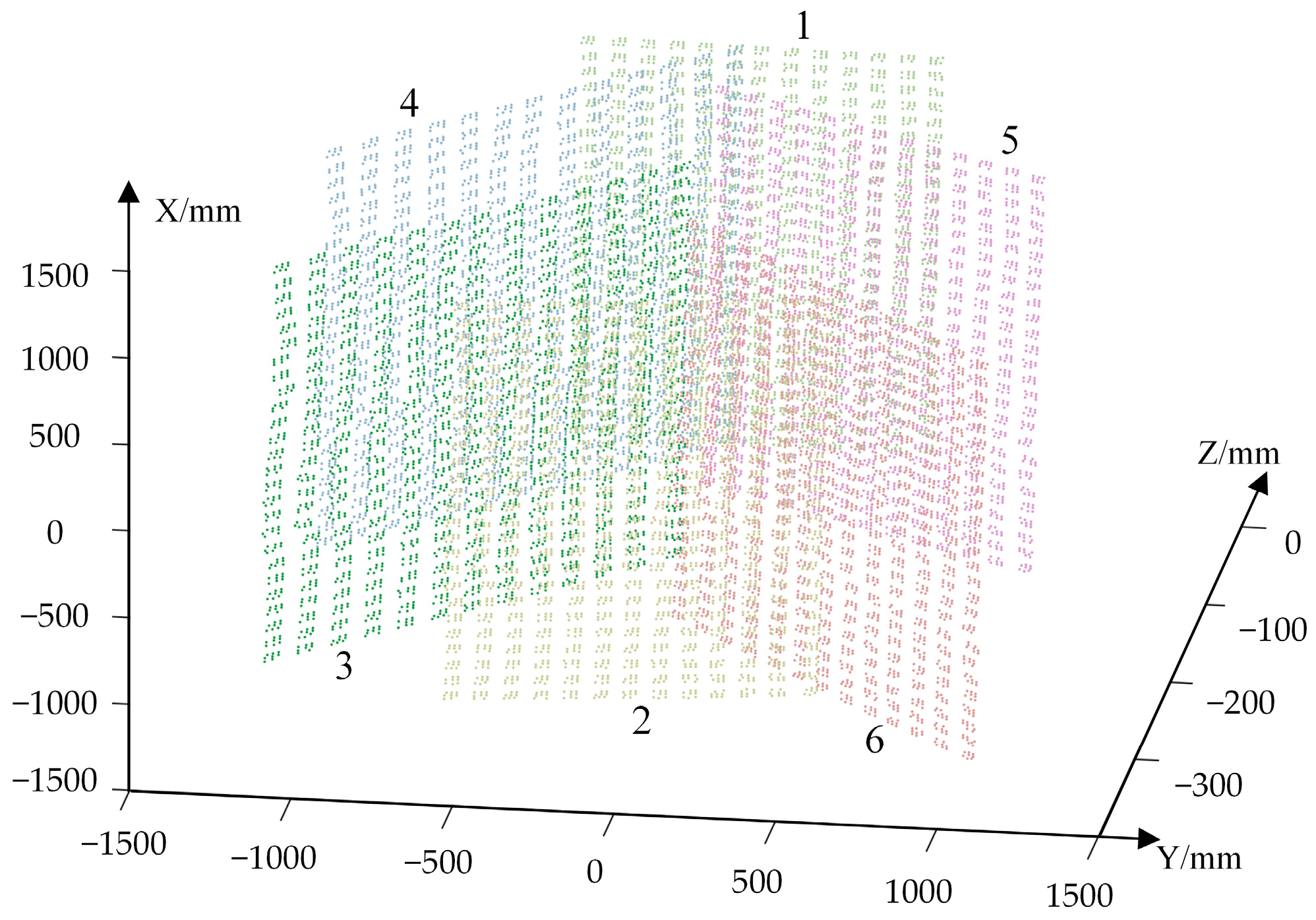

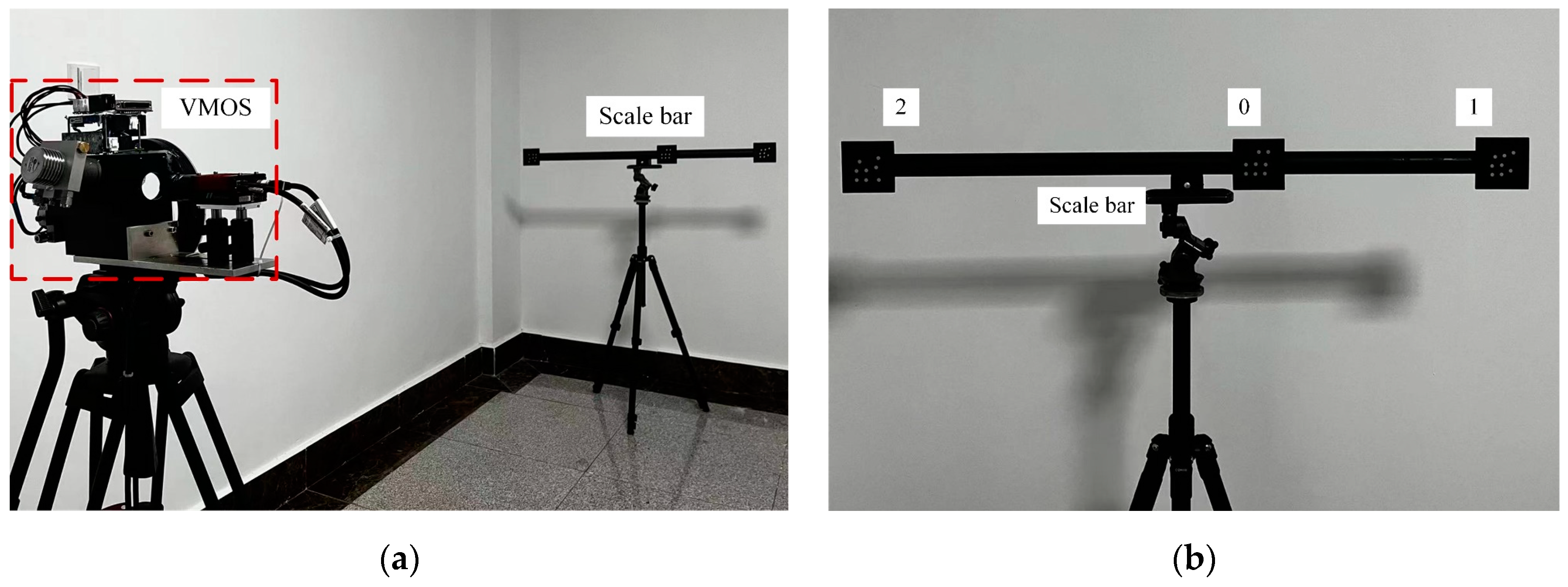



| MA (Pixel) | RMS (Pixel) | |
|---|---|---|
| Horizontal | 0.041 | 0.034 |
| Vertical | 0.043 | 0.035 |
| Overall | 0.067 | 0.038 |
| Direction | Initial | Optimized | ||
|---|---|---|---|---|
| MA (Pixel) | RMS (Pixel) | MA (Pixel) | RMS (Pixel) | |
| Horizontal | 0.206 | 0.143 | 0.200 | 0.132 |
| Vertical | 0.176 | 0.129 | 0.169 | 0.110 |
| Overall | 0.296 | 0.152 | 0.282 | 0.137 |
| AM (mm) | RMS (mm) | |
|---|---|---|
| Distance errors | 1.007 | 0.835 |
| Direction | MA (mm) | RMS (mm) |
|---|---|---|
| x | 0.153 | 0.142 |
| y | 0.181 | 0.088 |
| z | 1.370 | 0.776 |
| Full | 1.404 | 0.769 |
| AM (mm) | RMS (mm) | |
|---|---|---|
| Distance errors | 0.913 | 0.616 |
| 6D Pose Parameters | VMOS | Ordinary Camera | |
|---|---|---|---|
| Rotation error (°) | x-axis | 0.016 | 0.250 |
| y-axis | 0.046 | 0.020 | |
| z-axis | 0.024 | 0.126 | |
| Overall | 0.055 | 0.295 | |
| Translation error (mm) | x-direction | 0.376 | 0.098 |
| y-direction | 0.081 | 1.400 | |
| z-direction | 0.597 | 3.249 | |
| Overall | 0.710 | 3.539 | |
Disclaimer/Publisher’s Note: The statements, opinions and data contained in all publications are solely those of the individual author(s) and contributor(s) and not of MDPI and/or the editor(s). MDPI and/or the editor(s) disclaim responsibility for any injury to people or property resulting from any ideas, methods, instructions or products referred to in the content. |
© 2023 by the authors. Licensee MDPI, Basel, Switzerland. This article is an open access article distributed under the terms and conditions of the Creative Commons Attribution (CC BY) license (https://creativecommons.org/licenses/by/4.0/).
Share and Cite
Han, Z.; Zhang, L. A Virtual Multi-Ocular 3D Reconstruction System Using a Galvanometer Scanner and a Camera. Sensors 2023, 23, 3499. https://doi.org/10.3390/s23073499
Han Z, Zhang L. A Virtual Multi-Ocular 3D Reconstruction System Using a Galvanometer Scanner and a Camera. Sensors. 2023; 23(7):3499. https://doi.org/10.3390/s23073499
Chicago/Turabian StyleHan, Zidong, and Liyan Zhang. 2023. "A Virtual Multi-Ocular 3D Reconstruction System Using a Galvanometer Scanner and a Camera" Sensors 23, no. 7: 3499. https://doi.org/10.3390/s23073499
APA StyleHan, Z., & Zhang, L. (2023). A Virtual Multi-Ocular 3D Reconstruction System Using a Galvanometer Scanner and a Camera. Sensors, 23(7), 3499. https://doi.org/10.3390/s23073499


