
Investigation of the Effect of Debris Position on the Detection Stability of a Magnetic Plug Sensor Based on Alternating Current Bridge
 , , and
Abstract
:1. Introduction
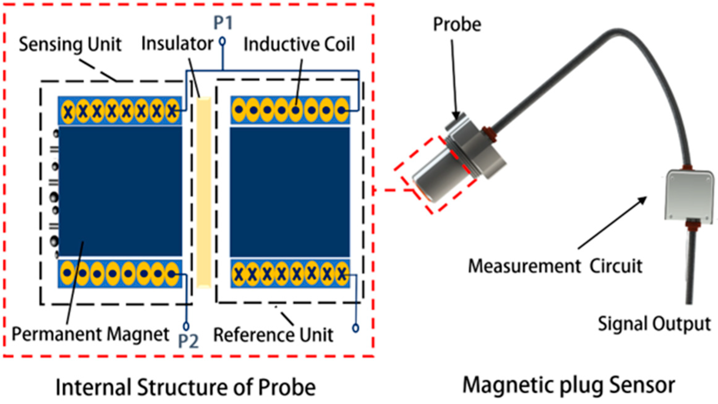
2. Sensor Structure
3. Modeling and Simulation
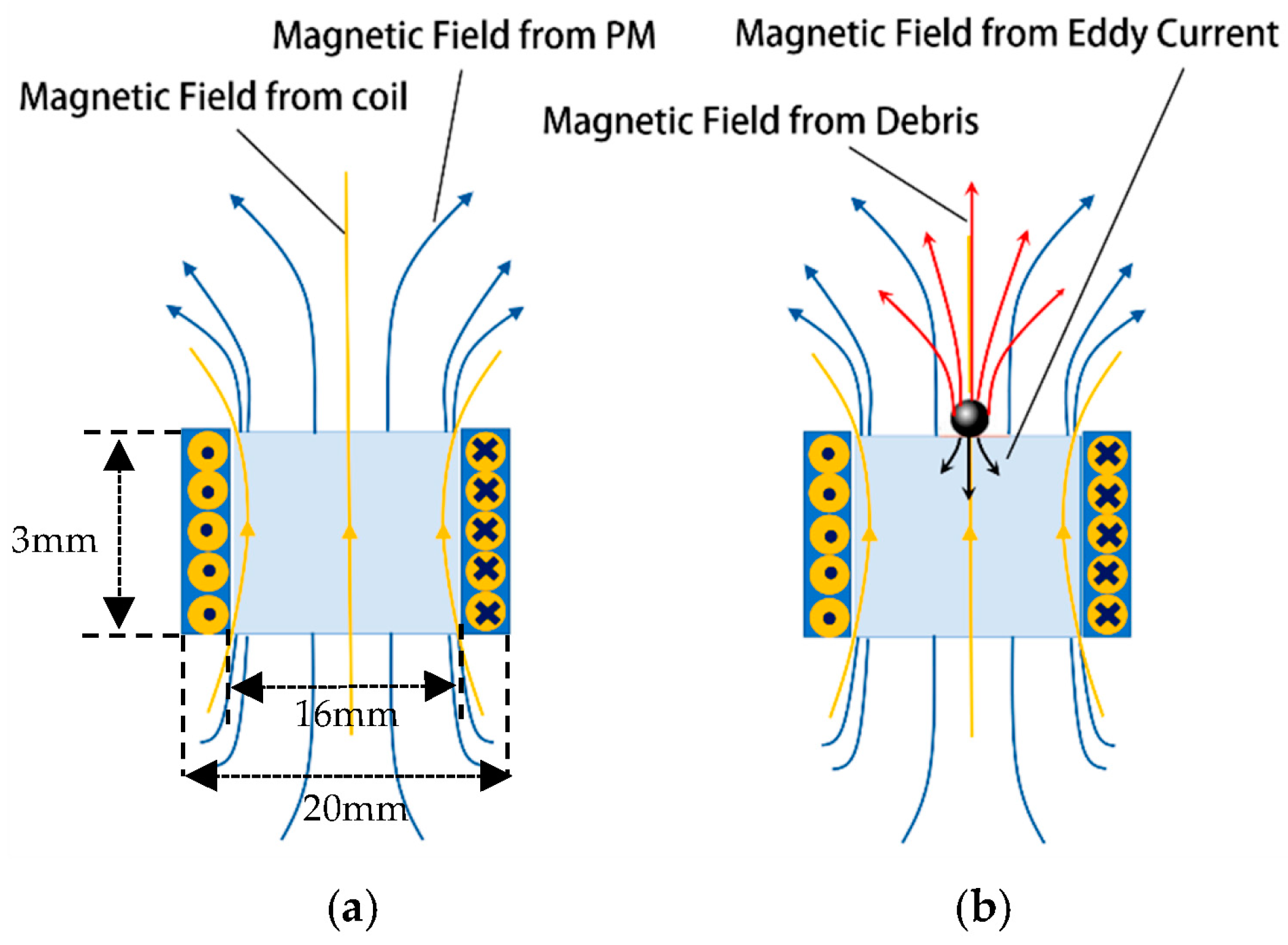
3.1. Theoretical Analysis
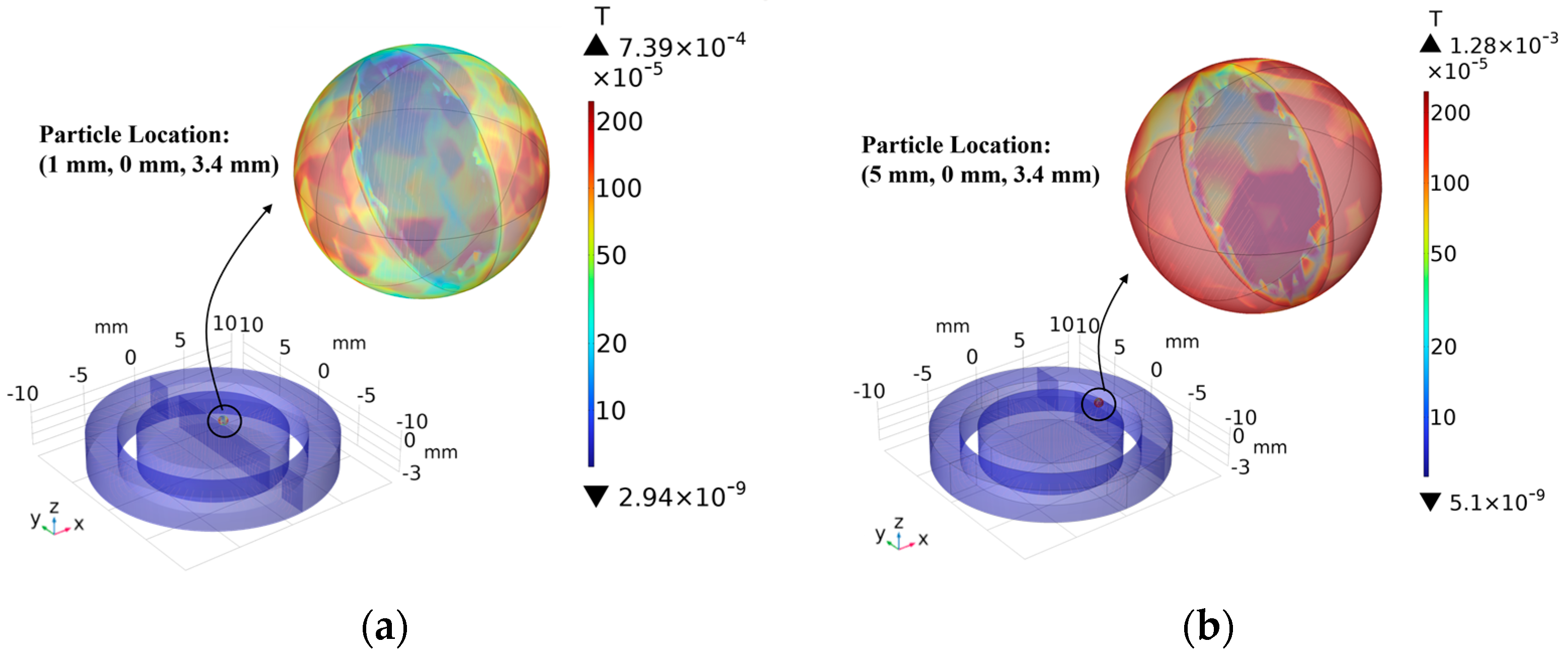
3.2. Finite Element Analysis
4. Experimental Validation
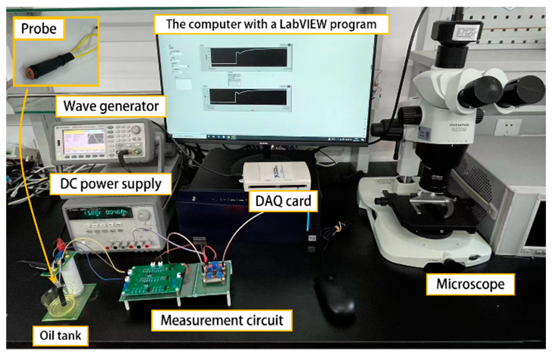
4.1. Experiment System
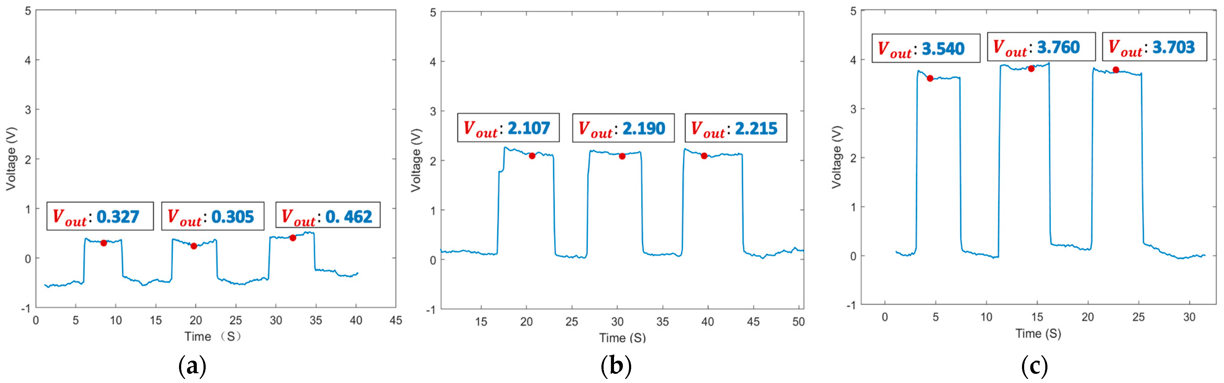
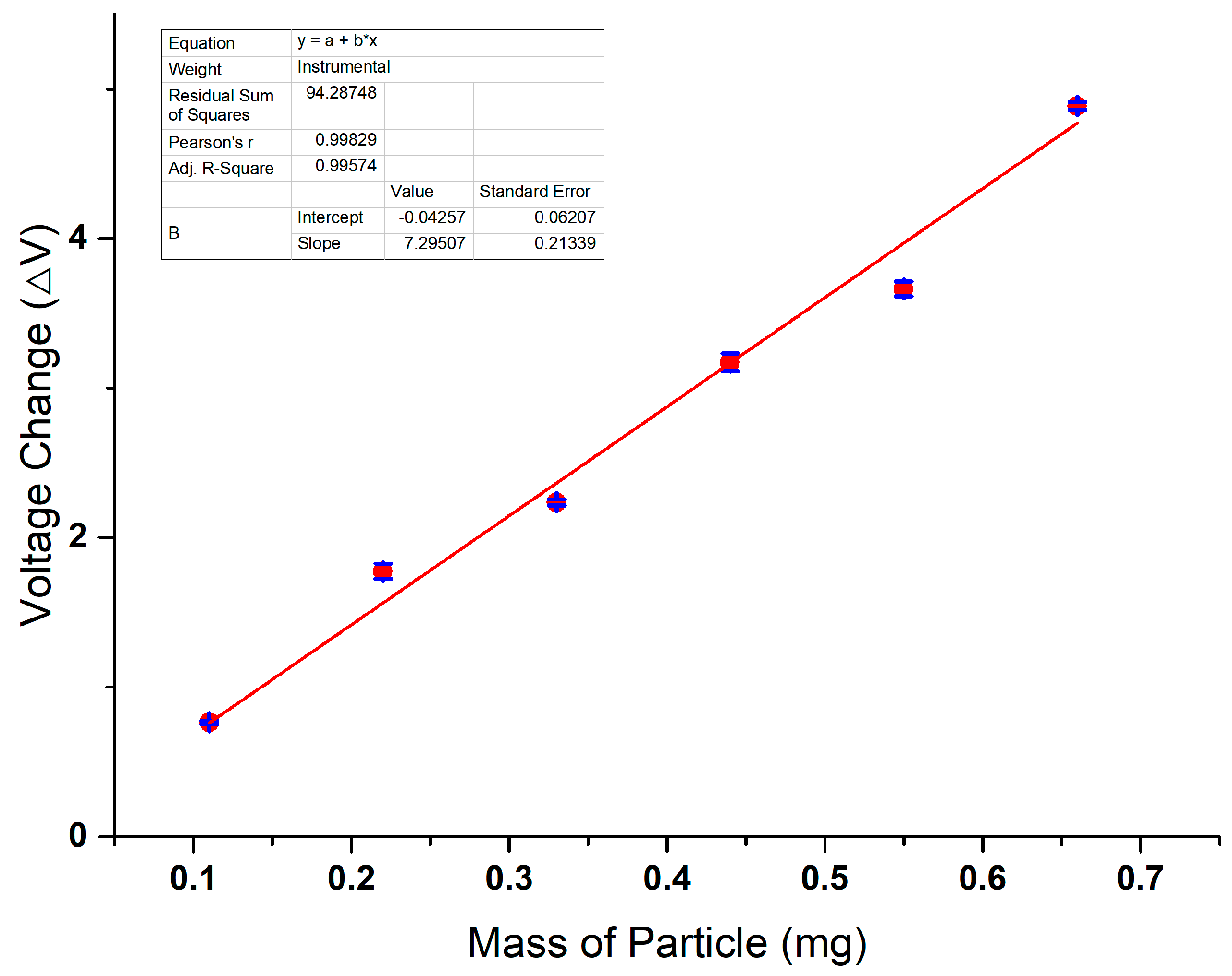
4.2. Sensitivity Test
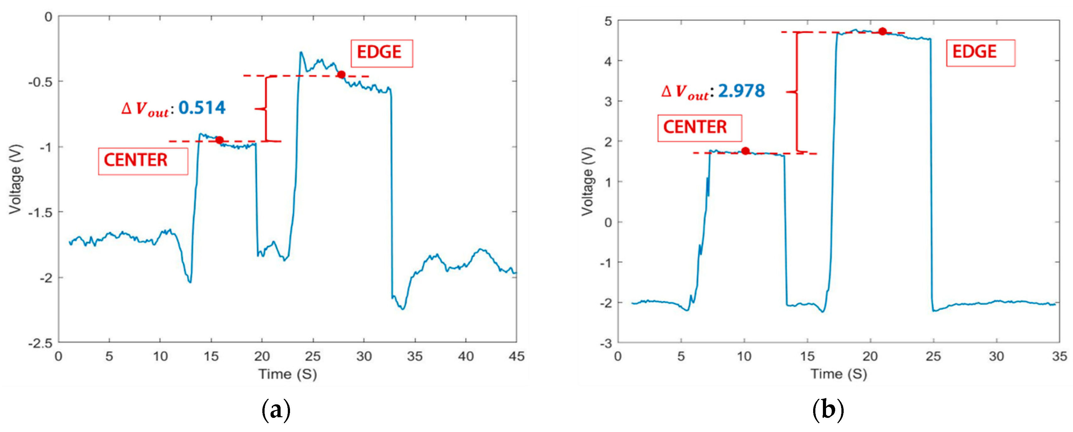
4.3. Stability Test
5. Discussion
6. Conclusions
Author Contributions
Funding
Institutional Review Board Statement
Informed Consent Statement
Data Availability Statement
Conflicts of Interest
References
- Sun, J.; Wang, L.; Li, J.; Li, F.; Li, J.; Lu, H. Online oil debris monitoring of rotating machinery: A detailed review of more than three decades. Mech. Syst. Signal Process. 2021, 149, 107341. [Google Scholar] [CrossRef]
- Zhu, X.; Zhong, C.; Zhe, J. Lubricating oil conditioning sensors for online machine health monitoring—A review. Tribol. Int. 2017, 109, 473–484. [Google Scholar] [CrossRef]
- Davis, J.R. Lubricant Analysis, 18th ed.; Metals Handbook, Tribology; ASM HandBook; ASM: Novelty, OH, USA, 1992; Volume 19, pp. 300–312. [Google Scholar]
- Myshkin, N.K.; Markova, L.V. Wear prediction for tirbosystems based on debris analysis. In On-line Condition Monitoring in Industrial Lubrication and Tribology, 8th ed.; Springer Nature: Cham, Switzerland, 2018; pp. 131–141. [Google Scholar]
- Qian, M.; Ren, Y.; Zhao, G.; Feng, Z. Ultrasensitive inductive debris sensor with a two-stage auto asymmetry compensation circuit. IEEE Trans. Ind. Electron. 2021, 68, 8885–8893. [Google Scholar] [CrossRef]
- Zhu, X.; Zhong, C.; Zhe, J. A high sensitivity wear debris sensor using ferrite cores for online oil condition monitoring. Meas. Sci. Technol. 2017, 28, 075102. [Google Scholar] [CrossRef]
- Yuan, Z.; Feng, S.; Tan, J.; Liu, H. A Passive Ferro-Particle Sensor of Lube-Oil Based on Single Permanent Magnetic Ring. IEEE Sens. J. 2022, 22, 8565–8573. [Google Scholar] [CrossRef]
- Feng, S.; Tan, J.; Wen, Y.; Fan, B.; Luo, J.; Li, R. Sensing Model for Detecting Ferromagnetic Debris Based on a High-Gradient Magnetostatic Field. IEEE/ASME Trans. Mechatron. 2022, 27, 2440–2449. [Google Scholar] [CrossRef]
- Shi, H.; Zhang, H.; Ma, L.; Rogers, F.; Zhao, X.; Zeng, L. An Impedance Debris Sensor Based on a High-Gradient Magnetic Field for High Sensitivity and High Throughput. IEEE Trans. Ind. Electron. 2021, 68, 5376–5384. [Google Scholar] [CrossRef]
- Baselt, D.R.; Lee, G.U.; Natesan, M.; Metzger, S.W.; Sheehan, P.E.; Colton, R.J. A biosensor based on magnetoresistance technology. Biosens. Bioelectron. 1998, 13, 731–739. [Google Scholar] [CrossRef] [PubMed]
- Miller, M.M.; Prinz, G.A.; Cheng, S.-F.; Bounnak, S. Detection of a micron-sized magnetic sphere using a ring-shaped anisotropic magnetoresistance-based sensor: A model for a magnetoresistance-based biosensor. Appl. Phys. Let-Ters 2002, 81, 2211–2213. [Google Scholar] [CrossRef]
- Chuma, E.L.; Iano, Y.; Roger, L.L.B.; de Oliveira, G.G.; Vaz, G.C. Novelty Sensor for Detection of Wear Particles in Oil Using Integrated Microwave Metamaterial Resonators with Neodymium Magnets. IEEE Sens. J. 2022, 22, 10508–10514. [Google Scholar] [CrossRef]
- Huang, J.; Xiang, Y. Injection-Locked-Oscillation-Based Active Sensor on Dual-Mode Folded SIW Rectangular Cavity for High-Resolution Detection to Moisture and Fe Particle in Lubricant Oil. IEEE Trans. Microw. Theory Tech. 2022, 71, 1600–1611. [Google Scholar] [CrossRef]
- Miller, J.; Kitaljevich, D. In-line oil debris monitor for aircraft engine condition assessment. In Proceedings of the 2000 IEEE Aerospace Conference, Big Sky, MT, USA, 25 March 2000; Volume 6, pp. 49–56. [Google Scholar] [CrossRef]
- Dempsey, P.J. Gear Damage Detection Using Oil Debris Analysis; National Aeronautics and Space Administration Glenn Research Center: Cleveland, OH, USA, 2001. [Google Scholar]
- Cao, Y.; Liu, R.; Du, J.; Yu, F.; Yang, Q.; He, Y.; Li, S. Gas Turbine Bearing Wear Monitoring Method Based on Magnetic Plug Inductance Sensor. In Proceedings of the ASME Turbo Expo 2018: Turbomachinery Technical Conference and Exposition, Rep. GT2018-75224, Oslo, Norway, 11–15 June 2018. [Google Scholar]
- Wang, H.B.; Yuan, F.; Gao, L.Y.; Huang, R.; Wang, W.S. Wear Debris Classification and Quantity and Size Calculation Using Convolutional Neural Network. In Communications in Computer and Information Science; Springer: Singapore, 2019; Volume 1137, pp. 470–486. [Google Scholar]
- Harkemanne, E.; Berten, O.; Hendrick, P. Analysis and Testing of Debris Monitoring Sensors for Aircraft Lubrication Systems. In Proceedings of the International Conference on Experimental Mechanics, The Egg, Brussels, 1 July 2018; Volume 2, pp. 461–467. [Google Scholar] [CrossRef]
- Itomi, S. Oil Condition Sensor. U.S. Patent 7 112 973, 26 September 2006. [Google Scholar]
- Muthuvel, P.; George, B.; Ramadass, G.A. Magnetic-Capacitive Wear Debris Sensor Plug for Condition Monitoring of Hydraulic Systems. IEEE Sens. J. 2018, 18, 9120–9127. [Google Scholar] [CrossRef]
- Bravo-Imaz, I.; Garcia-Arribas, A.; Gorritxategi, E.; Arnaiz, A.; Barandiaran, J.M. Magnetoelastic Viscosity Sensor for On-Line Status Assessment of Lubricant Oils. IEEE Trans. Magn. 2013, 49, 113–116. [Google Scholar] [CrossRef]
- Blyakhman, F.A.; Buznikov, N.A.; Sklyar, T.F.; Safronov, A.P.; Golubeva, E.V.; Svalov, A.V.; Sokolov, S.Y.; Melnikov, G.Y.; Orue, I.; Kurlyandskaya, G.V. Mechanical, Electrical and Magnetic Properties of Ferrogels with Embedded Iron Oxide Nanoparticles Obtained by Laser Target Evaporation: Focus on Multifunctional Biosensor Applications. Sensors 2018, 18, 872. [Google Scholar] [CrossRef]
- Zhang, X.; Zeng, L.; Zhang, H.; Huang, S. Magnetization Model and Detection Mechanism of a Microparticle in a Harmonic Magnetic Field. IEEE/ASME Trans. Mechatronics 2019, 24, 1882–1892. [Google Scholar] [CrossRef]


| Position of the particle in the X-axis (mm) | 1 | 2 | 3 | 4 | 5 |
| Detection coil inductance (μH) | 4558.3 | 4561.0 | 4565.9 | 4571.5 | 4571.5 |
Disclaimer/Publisher’s Note: The statements, opinions and data contained in all publications are solely those of the individual author(s) and contributor(s) and not of MDPI and/or the editor(s). MDPI and/or the editor(s) disclaim responsibility for any injury to people or property resulting from any ideas, methods, instructions or products referred to in the content. |
© 2023 by the authors. Licensee MDPI, Basel, Switzerland. This article is an open access article distributed under the terms and conditions of the Creative Commons Attribution (CC BY) license (https://creativecommons.org/licenses/by/4.0/).
Share and Cite
Zhang, S.; Xie, Y.; Zhang, L.; Zhang, Y.; Zhang, S.; Bai, C.; Li, W. Investigation of the Effect of Debris Position on the Detection Stability of a Magnetic Plug Sensor Based on Alternating Current Bridge. Sensors 2024, 24, 55. https://doi.org/10.3390/s24010055
Zhang S, Xie Y, Zhang L, Zhang Y, Zhang S, Bai C, Li W. Investigation of the Effect of Debris Position on the Detection Stability of a Magnetic Plug Sensor Based on Alternating Current Bridge. Sensors. 2024; 24(1):55. https://doi.org/10.3390/s24010055
Chicago/Turabian StyleZhang, Siqi, Yucai Xie, Lianfeng Zhang, Yuwei Zhang, Shuyao Zhang, Chenzhao Bai, and Wei Li. 2024. "Investigation of the Effect of Debris Position on the Detection Stability of a Magnetic Plug Sensor Based on Alternating Current Bridge" Sensors 24, no. 1: 55. https://doi.org/10.3390/s24010055