
Self-Tuning of Signal Detection Level for Energy Detection-Based Carrier Sense in Low-Power Wide-Area Networks

Abstract
:1. Introduction
2. Related Works and Original Contribution
2.1. Related Works
2.2. Original Contribution
- We propose a simple self-tuning method for the carrier sense level for the energy detection-based carrier sense in the Sub-GHz band of the LPWAN. The proposed method can autonomously determine the carrier sense level of each end device.
- Unlike these works shown in the previous subsection, we employ acknowledgment (ACK) protocols, which are already implemented in most LPWA communications, in LPWANs for the proposed self-tuning method. For example, all end devices for LoRaWANs must implement Class A, which specifies ACK packets [19], while Wi-SUN equips the ACK frame [23]. The signal detection level of the energy detection-based carrier sense determines whether the reception of ACK packets is successful or not. By employing ACK protocols, the autonomous decentralized determinations of the carrier sense level can be realized for each end device. Therefore, the proposed method is applicable to all LPWA schemes with the ACK mechanism, and this is an advantage of the proposed method.
- Numerical examples show that the proposed method can solve the trade-off between the accuracy of the carrier sense and energy efficiency under the given target packet delivery ratio.
3. Preliminary Notion
3.1. LPWAN
3.2. Energy Detection-Based Carrier Sense in LPWANs
4. Self-Tuning Method of Signal Detection Level for Energy Detection-Based Carrier Sense
4.1. Overview of Proposed Method
4.2. Self-Tuning Method for Determination of Carrier Sense Level
4.2.1. Case:
4.2.2. Case:
| Algorithm 1 Self-tuning algorithm at kth end device |
5. Numerical Examples
5.1. Parameter Setup
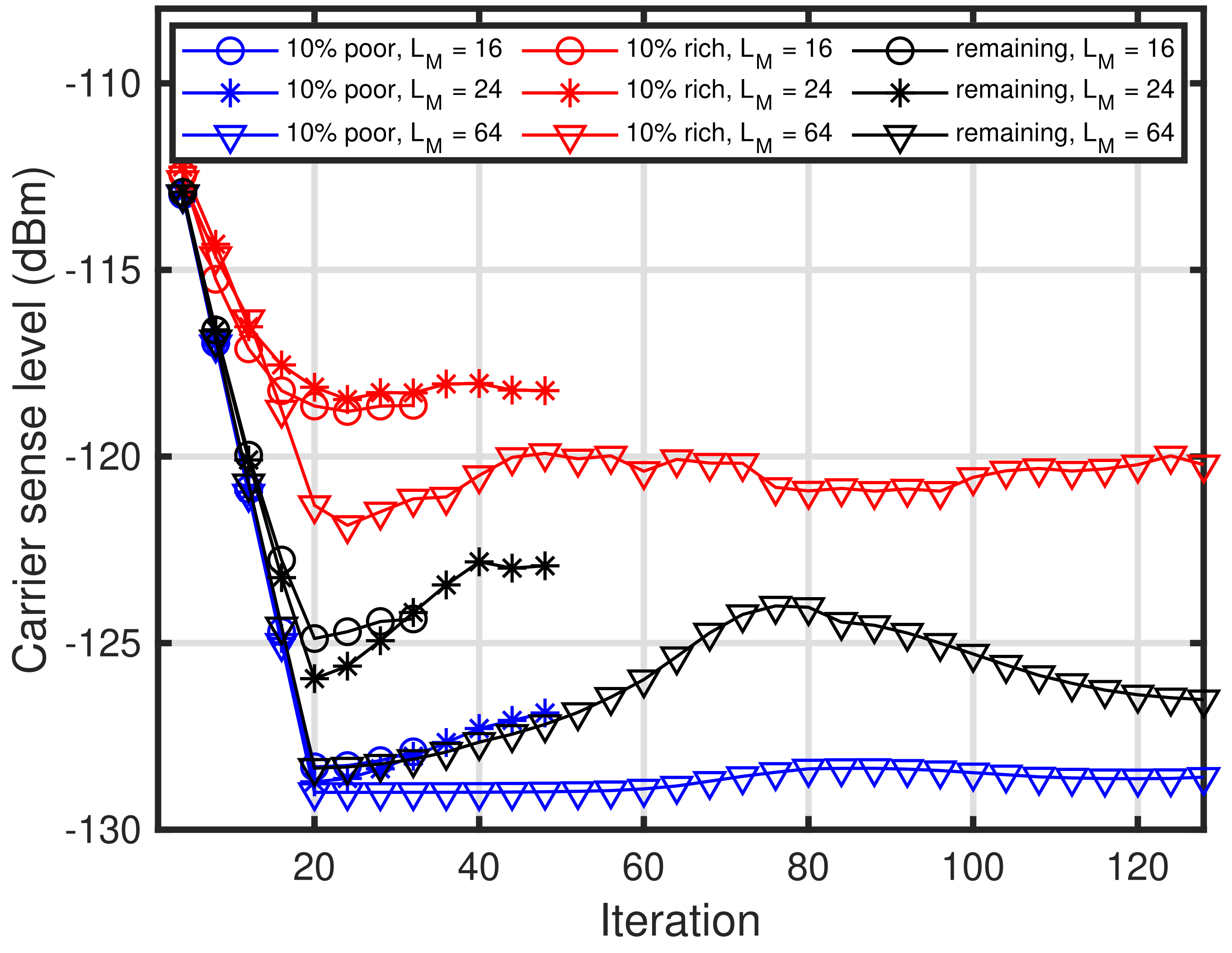
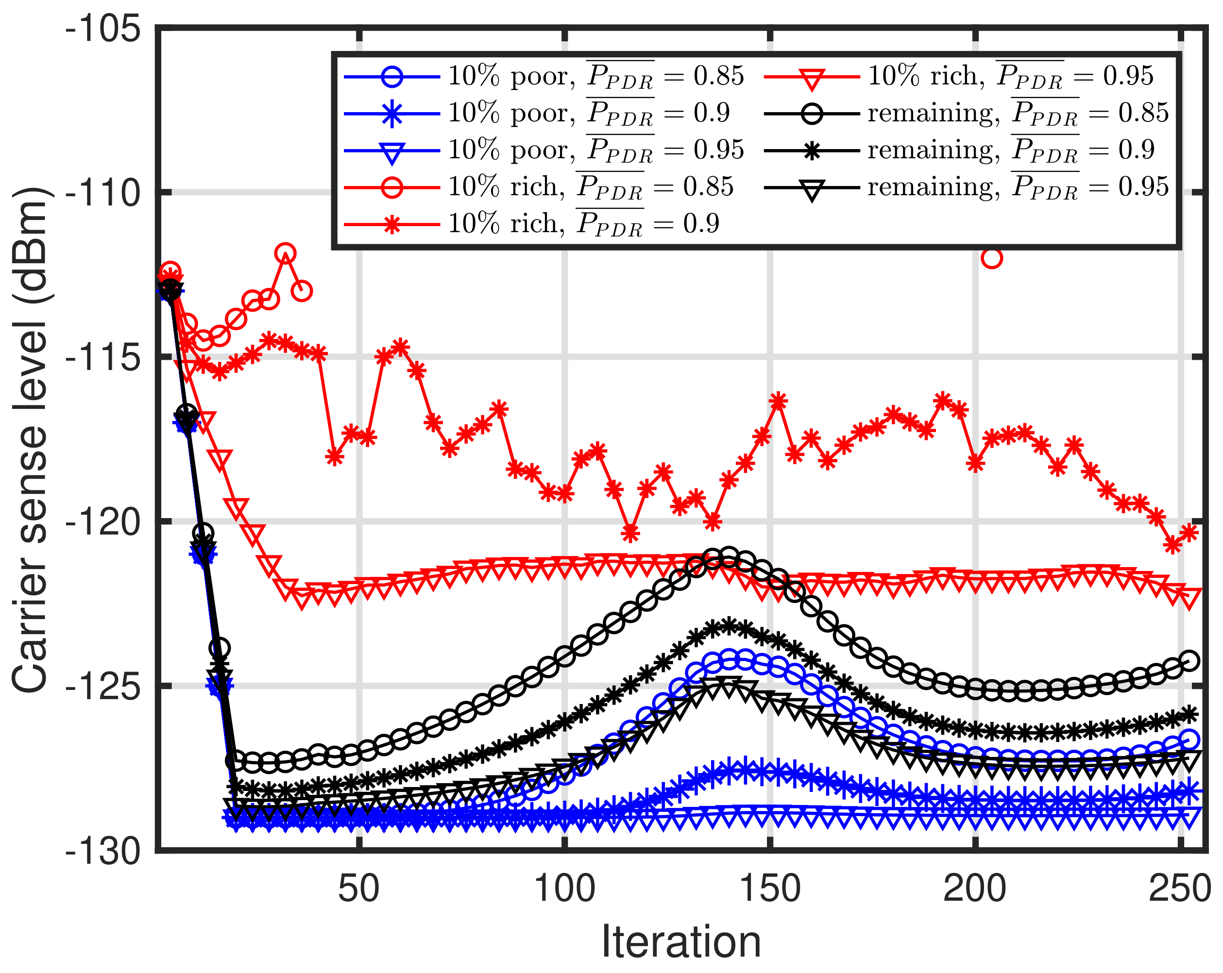
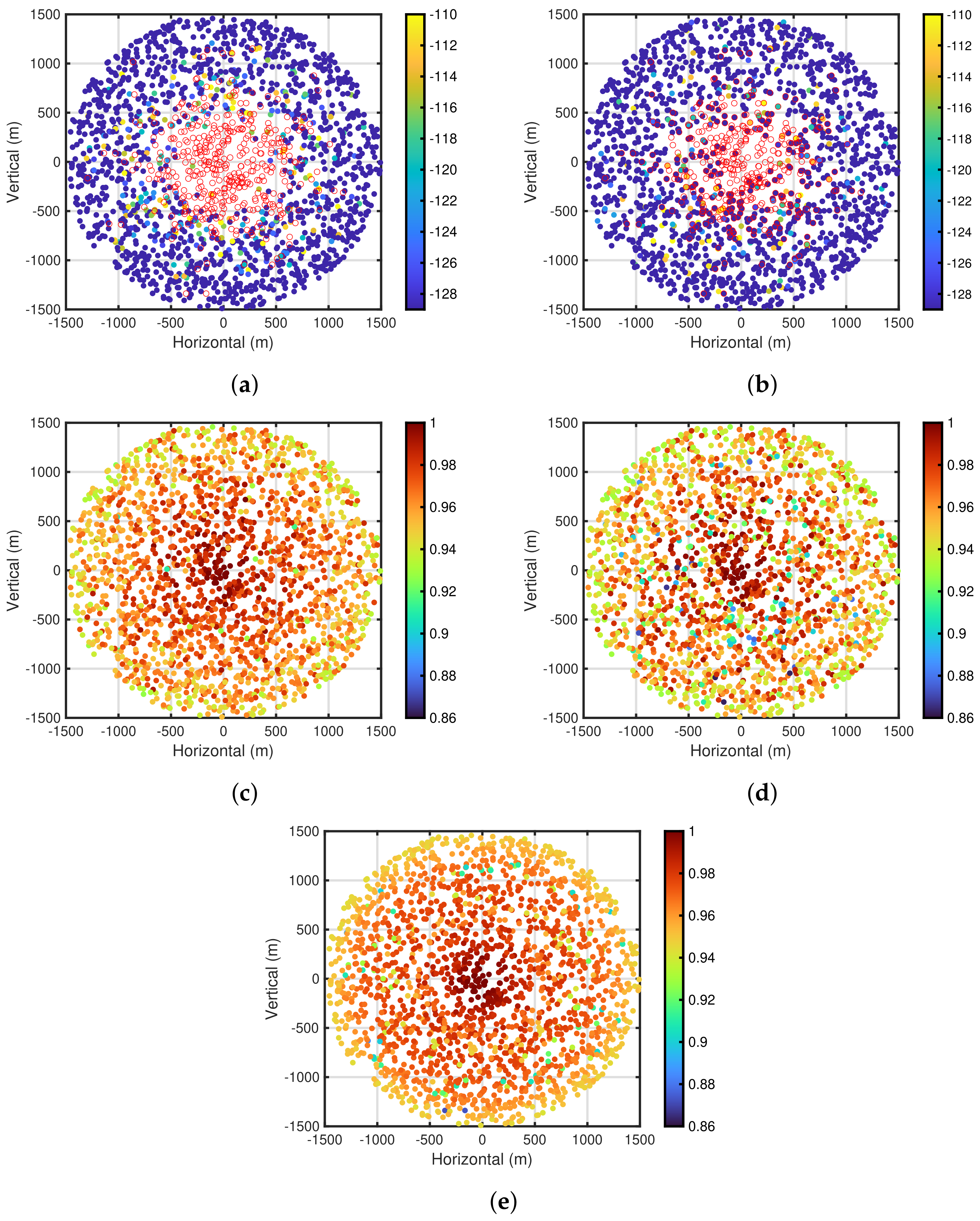
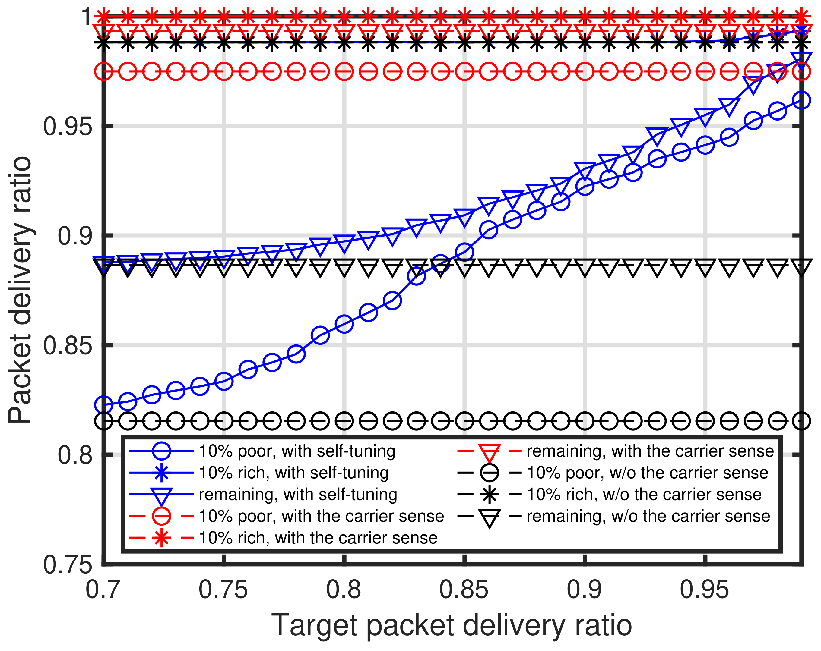
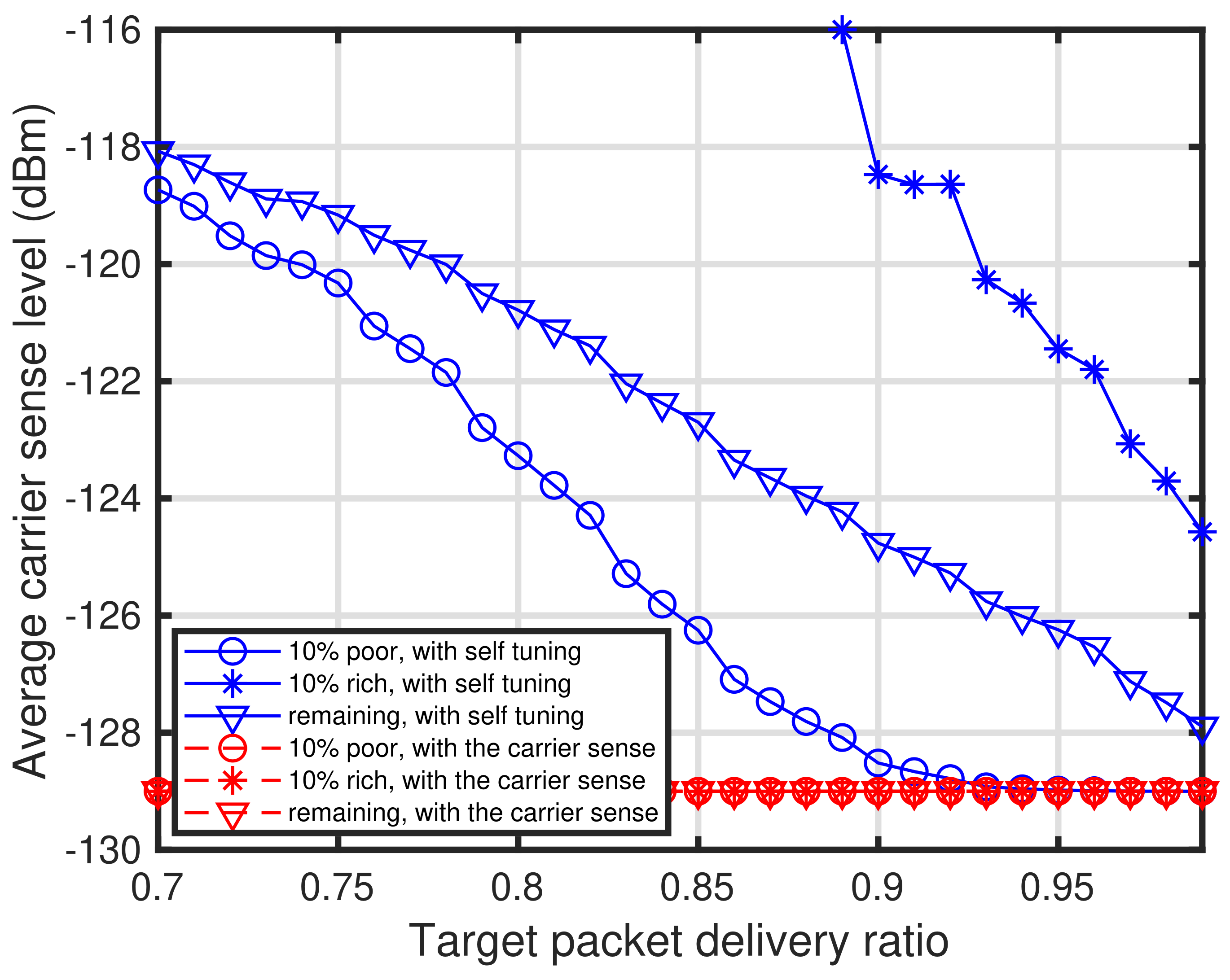
5.2. Fundamental Characteristics of Self-Tuning Method
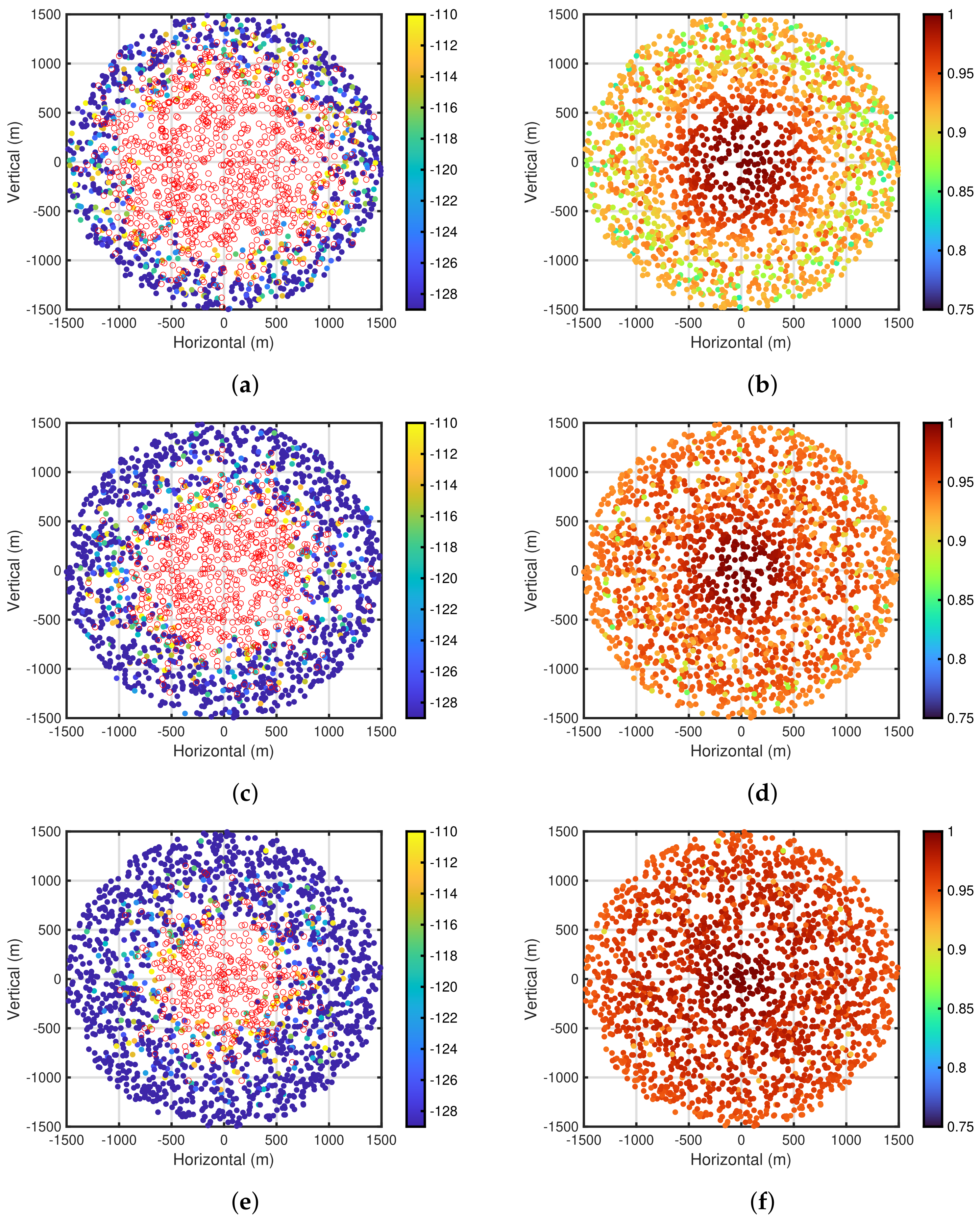
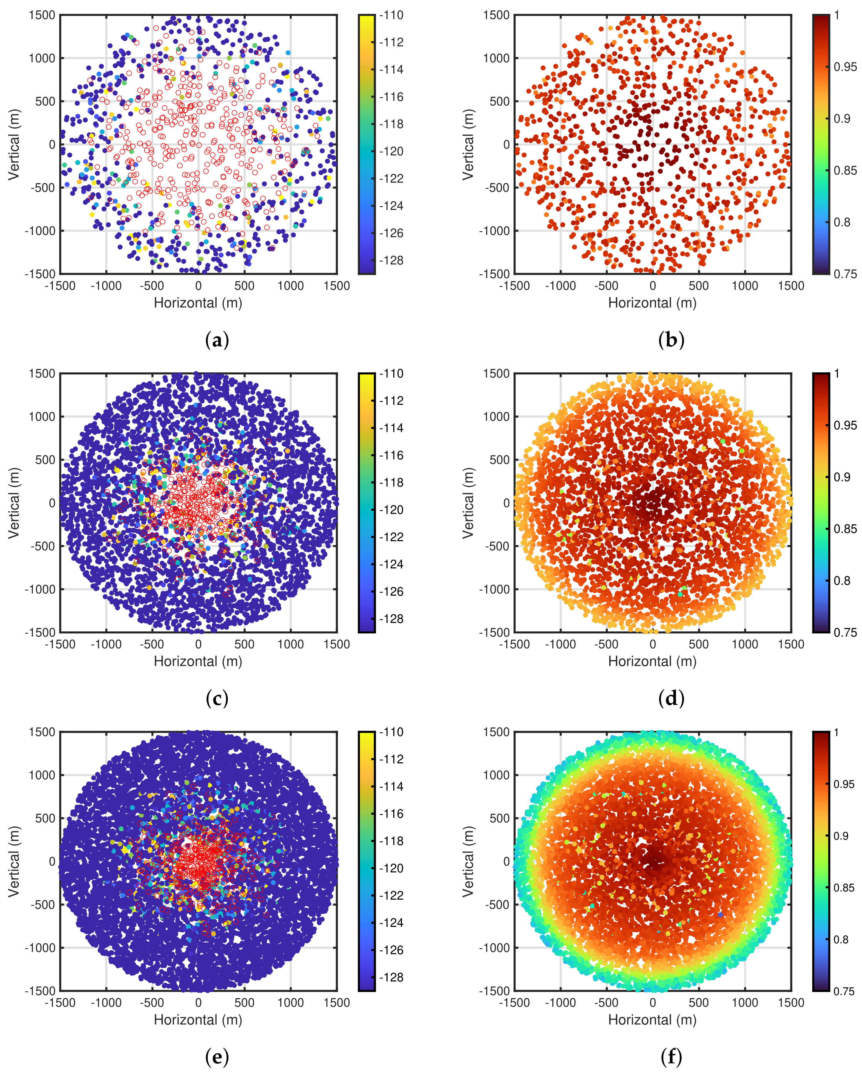
5.3. Characteristics of Proposed Self-Tuning Method for Channel Changing Owing to Some Factors
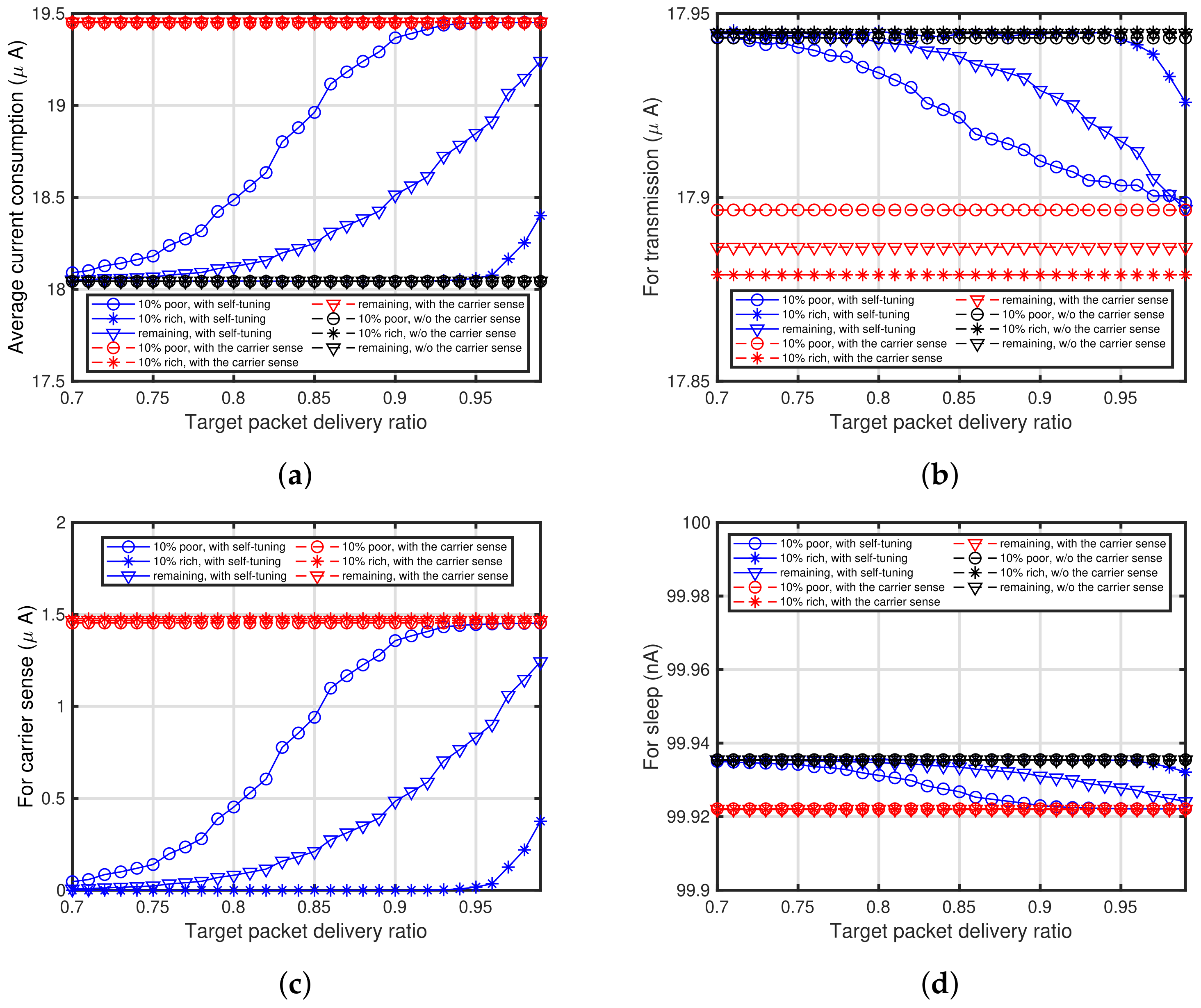
5.4. Characteristics of Self-Tuning Method Regarding Energy Consumption
6. Conclusions
Author Contributions
Funding
Data Availability Statement
Conflicts of Interest
References
- Shahid, M.; Ahmed, A.; Zhibo, P.; Ammar, R.; Fung, T.K.; Jonathan, R. Massive Internet of Things for Industrial Applications: Addressing Wireless IoT Connectivity Challenges and Ecosystem Fragmentation. IEEE Ind. Electron. Mag. 2017, 11, 28–33. [Google Scholar]
- Luca, L.; Filippo, B.; Gaetano, P.; Lo, B.L. Industrial LoRa: A Novel Medium Access Strategy for LoRa in Industry 4.0 Applications. In Proceedings of the IECON 2018—44th Annual Conference of the IEEE Industrial Electronics Society, Washington, DC, USA, 21–23 October 2018; pp. 4141–4146. [Google Scholar]
- Premsankar, G.; Ghaddar, B.; Slabicki, M.; Francesco, M.D. Optimal Configuration of LoRa Networks in Smart Cities. IEEE Trans. Ind. Inform. 2020, 16, 7243–7254. [Google Scholar] [CrossRef]
- Raza, U.; Kulkami, P.; Sooriyabandara, M. Low Power Wide Area Networks: An Overview. IEEE Commun. Surv. Tutor. 2017, 19, 855–873. [Google Scholar] [CrossRef]
- Kleinrock, L.; Tobagi, F. Packet Switching in Radio Channels: Part I - Carrier Sense Multiple-Access Modes and Their Throughput-Delay Characteristics. IEEE Trans. Commun. 1975, 23, 1400–1416. [Google Scholar] [CrossRef]
- Kim, T.H.; Ni, J.; Srikant, R.; Vaidya, N.H. Throughput-Optimal CSMA With Imperfect Carrier Sensing. IEEE/ACM Trans. Netw. 2013, 21, 1636–1650. [Google Scholar] [CrossRef]
- IEEE Std 802.11-2016 (Revision of IEEE Std 802.11-2012); IEEE Standard for Information Technology—Telecommunications and Information Exchange between Systems Local and Metropolitan Area Networks—Specific Requirements—Part 11: Wireless LAN Medium Access Control (MAC) and Physical Layer (PHY) Specifications. IEEE: Piscataway Township, NJ, USA, 2016; pp. 1–3534.
- Kay, S.M. Fundamentals of Statistical Signal Processing: Detection Theory; Prentice Hall: Englewood Cliffs, NJ, USA, 1998. [Google Scholar]
- Urkowitz, H. Energy Detection of Unknown Deterministic Signals. Proc. IEEE 1967, 55, 523–531. [Google Scholar] [CrossRef]
- Gardner, W. Exploitation of Spectral Redundancy in Cyclostationary Signals. IEEE Signal Process. Mag. 1991, 8, 14–36. [Google Scholar] [CrossRef]
- ARIB STD-T108; 920MHz-Band Telemeter, Telecontrol and Data Transmission Radio Equipment v. 1.2. Association of Radio Industiries and Businesses: Chiyoda, Japan, 2018. (In Japanese)
- Narieda, S.; Fujii, T. Energy Detection Based Carrier Sense in LPWAN. IEEE Access 2023, 11, 79105–79119. [Google Scholar] [CrossRef]
- Ju, Y.; Cao, Z.; Chen, Y.; Liu, L.; Pei, Q.; Mumtaz, S.; Dong, M.; Guizani, M. NOMA-Assisted Secure Offloading for Vehicular Edge Computing Networks With Asynchronous Deep Reinforcement Learning. IEEE Trans. Intell. Transp. Syst. 2024, 25, 2627–2640. [Google Scholar] [CrossRef]
- Rallis, K.G.; Papanikolaou, V.K.; Diamantoulakis, P.D.; Tegos, S.A.; Dowhuszko, A.A.; Khalighi, M.A.; Karagiannidis, G.K. Energy Efficient Cooperative Communications in Aggregated VLC/RF Networks With NOMA. IEEE Trans. Commun. 2023, 71, 5408–5419. [Google Scholar] [CrossRef]
- Zorbas, D.; O’Flynn, B. Autonomous Collision-Free Scheduling for LoRa-Based Industrial Internet of Things. In Proceedings of the 2019 IEEE 20th International Symposium on “A World of Wireless, Mobile and Multimedia Networks” (WoWMoM), Washington, DC, USA, 10–12 June 2019; pp. 1–5. [Google Scholar]
- Zorbas, D.; Abdelfadeel, K.; Lotzanikolaou, P.; Pesch, D. TS-LoRa: Time-Slotted LoRaWAN for the Industrial Internet of Things. Comput. Commun. 2020, 153, 1–10. [Google Scholar] [CrossRef]
- Alahmadi, H.; Bouabdallah, F.; Al-Dubai, A.; Ghaleb, B. A Novel Autonomous Time-Slotted LoRa MAC Protocol with Adaptive Frame Sizes. In Proceedings of the 2023 International Wireless Communications and Mobile Computing (IWCMC), Marrakesh, Morocco, 19–23 June 2023; pp. 917–922. [Google Scholar]
- Alahmadi, H.; Bouabdallah, F.; Al-Dubai, A. A Novel Time-Slotted LoRa MAC Protocol for Scalable IoT Networks. Future Gener. Comput. Syst. 2022, 134, 287–302. [Google Scholar] [CrossRef]
- LoRa Alliance. Available online: https://lora-alliance.org/ (accessed on 17 March 2022).
- Finnegan, J.; Farrell, R.; Brown, S. Analysis and Enhancement of the LoRaWAN Adaptive Data Rate Scheme. IEEE Internet Things J. 2020, 7, 7171–7180. [Google Scholar] [CrossRef]
- Marini, R.; Cerroni, W.; Buratti, C. A Novel Collision-Aware Adaptive Data Rate Algorithm for LoRaWAN Networks. IEEE Internet Things J. 2021, 8, 2670–2680. [Google Scholar] [CrossRef]
- Garlisi, D.; Tinnirello, I.; Bianchi, G.; Cuomo, F. Capture Aware Sequential Waterfilling for LoRaWAN Adaptive Data Rate. IEEE Trans. Wirel. Commun. 2021, 20, 2019–2033. [Google Scholar] [CrossRef]
- Samejima, K.; Okumura, R.; Mizutani, K.; Harada, H. Evaluation of CSL-based Low Power MAC Protocol for Wireless Smart Metering Networks. In Proceedings of the 2020 IEEE 17th Annual Consumer Communications and Networking Conference (CCNC), Las Vegas, NV, USA, 10–13 January 2020; pp. 1–6. [Google Scholar]
- Available online: https://www.semtech.com/products/wireless-rf/lora-transceivers/sx1276 (accessed on 17 March 2022).
- Pollin, S.; Ergen, M.; Ergen, S.C.; Bougard, B.; Der Perre, L.V.; Moerman, I.; Bahai, A.; Varaiya, P.; Catthoor, F. Performance Analysis of Slotted Carrier Sense IEEE 802.15.4 Medium Access Layer. IEEE Trans. Wirel. Commun. 2008, 7, 3359–3371. [Google Scholar] [CrossRef]
- Proakis, J.G. Digital Communications, 4th ed.; McGraw-Hill: New York, NY, USA, 2001. [Google Scholar]
- Tandra, R.; Sahai, A. SNR Walls for Signal Detection. IEEE J. Sel. Top. Signal Process. 2008, 2, 4–17. [Google Scholar] [CrossRef]
- Mariani, A.; Giorgetti, A.; Chiani, M. Effects of Noise Power Estimation on Energy Detection for Cognitive Radio Applications. IEEE Trans. Commun. 2011, 59, 3410–3420. [Google Scholar] [CrossRef]
- Narieda, S.; Fujii, T. On Execution at End Devices for Energy Detection Based Carrier Sense in LPWAN. In Proceedings of the 2024 IEEE 21th Annual Consumer Communications and Networking Conference (CCNC), Las Vegas, NV, USA, 6–9 January 2024; pp. 920–923. [Google Scholar]
- Tsuchiya, H.; Mikami, M.; Kurono, M. A Study of the Propagation Channel Modeling for Smart Meter Communications—Measurement and Evaluation of the Propagation Path Loss in a Residential, an Urban and a Suburban Area; Central Research Institute of Electric Power Industry (CRIEPI): Tokyo, Japan, 2012; Volume R11031, pp. 1–28. [Google Scholar]


| Parameter | Value |
|---|---|
| Packet transmission | 35 mA |
| Carrier sense | mA |
| Sleep | 100 nA |
| Parameter | Variable | Value |
|---|---|---|
| Number of end devices | 200 | |
| Radius of communication areas | R | 1500 m |
| Path loss exponent | (suburban) | |
| (end device–gateway) | ||
| Path loss exponent | (suburban) | |
| (end device–end device) | ||
| Transmit power at end device | 13 dBm | |
| Average transmission period | 300 s | |
| (Poisson distribution) | ||
| Length of packet | ms | |
| Spreading factor (end devices) | 7 | |
| Maximum carrier sense time | 3 | |
| Carrier frequency | 920 MHz | |
| Noise figure at receiver | 6 dB | |
| Number of channels used | − | 1 |
| Lower bound of carrier sense level | dBm | |
| Upper bound of carrier sense level | dBm | |
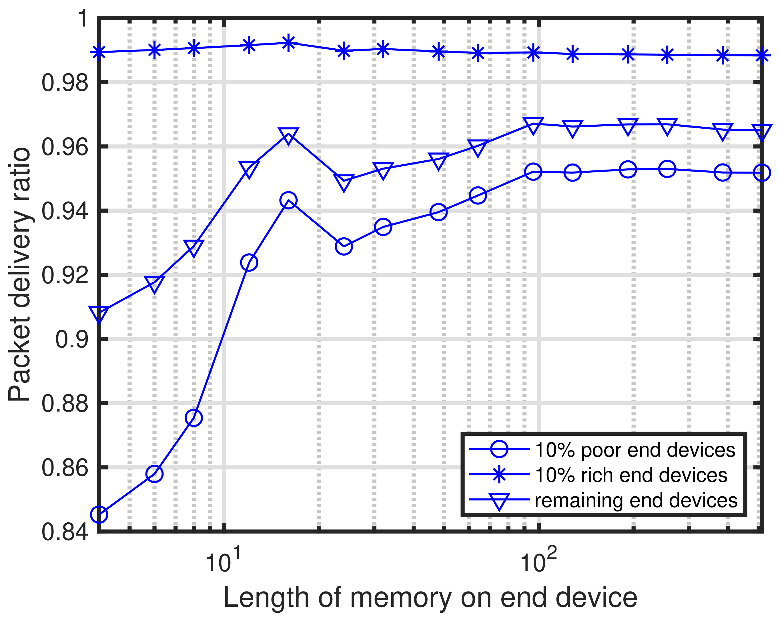
| Length of memory for ACK result | 128 | |
| Length of self-tuning period | 256 ACKs | |
| Transmit power at gateway | − | 13 dBm |
| Length of ACK | − | ms |
| Spreading factor (gateway) | 7 | |
| Carrier sense level at gateway | − | dBm |
| Target signal detection probability | ||
| Target false alarm probability | ||
| Current consumption of end devices | − | Table 1 |
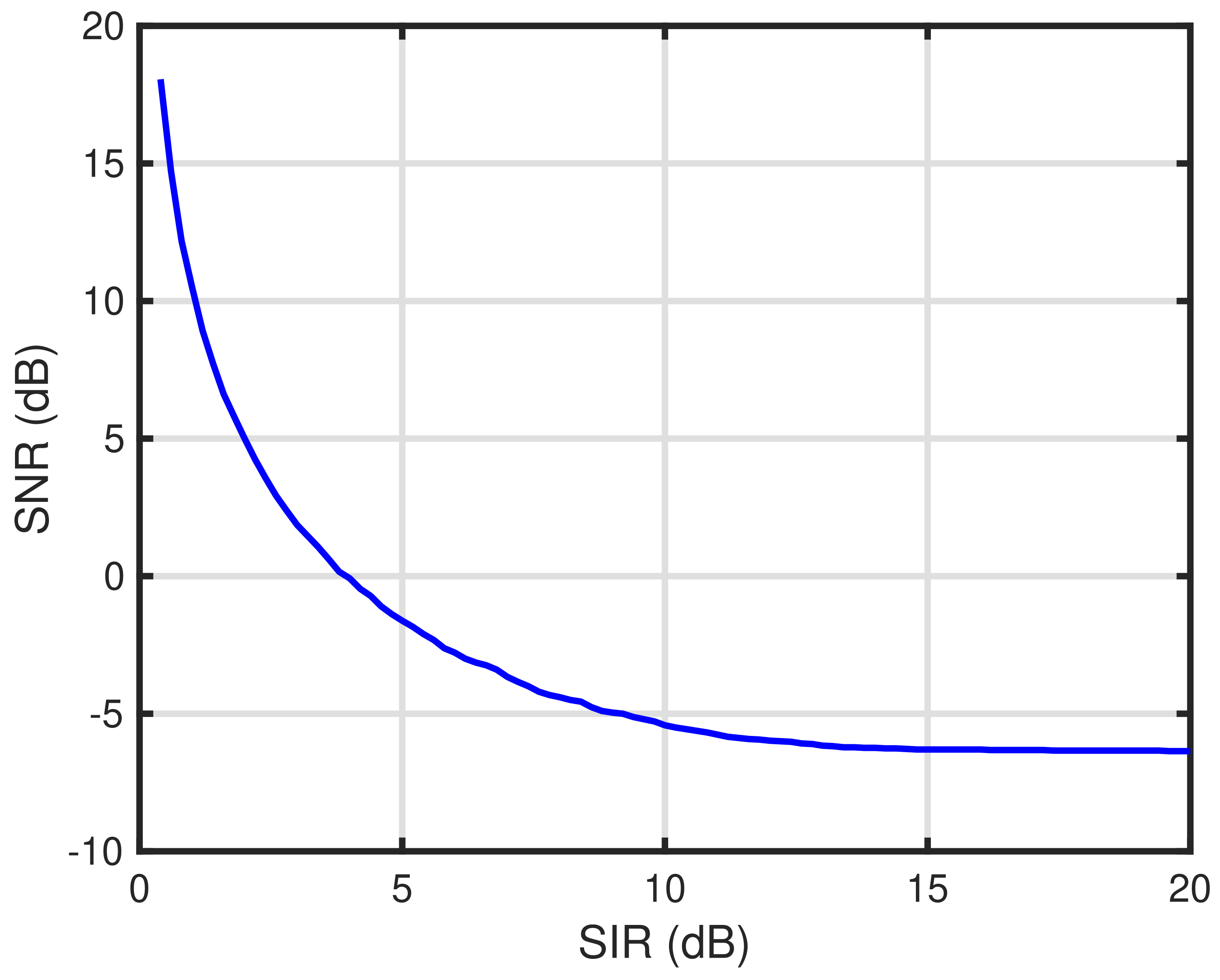
| Capture effect | − | Figure 3 |
Disclaimer/Publisher’s Note: The statements, opinions and data contained in all publications are solely those of the individual author(s) and contributor(s) and not of MDPI and/or the editor(s). MDPI and/or the editor(s) disclaim responsibility for any injury to people or property resulting from any ideas, methods, instructions or products referred to in the content. |
© 2024 by the authors. Licensee MDPI, Basel, Switzerland. This article is an open access article distributed under the terms and conditions of the Creative Commons Attribution (CC BY) license (https://creativecommons.org/licenses/by/4.0/).
Share and Cite
Narieda, S.; Fujii, T. Self-Tuning of Signal Detection Level for Energy Detection-Based Carrier Sense in Low-Power Wide-Area Networks. Sensors 2024, 24, 3368. https://doi.org/10.3390/s24113368
Narieda S, Fujii T. Self-Tuning of Signal Detection Level for Energy Detection-Based Carrier Sense in Low-Power Wide-Area Networks. Sensors. 2024; 24(11):3368. https://doi.org/10.3390/s24113368
Chicago/Turabian StyleNarieda, Shusuke, and Takeo Fujii. 2024. "Self-Tuning of Signal Detection Level for Energy Detection-Based Carrier Sense in Low-Power Wide-Area Networks" Sensors 24, no. 11: 3368. https://doi.org/10.3390/s24113368