
Development of an In-Pipe Inspection Robot for Large-Diameter Water Pipes

 ,
,
Abstract
1. Introduction
2. Composition of In-Pipe Inspection Robot
2.1. Design Constriaints of an In-Pipe Inspection Robot
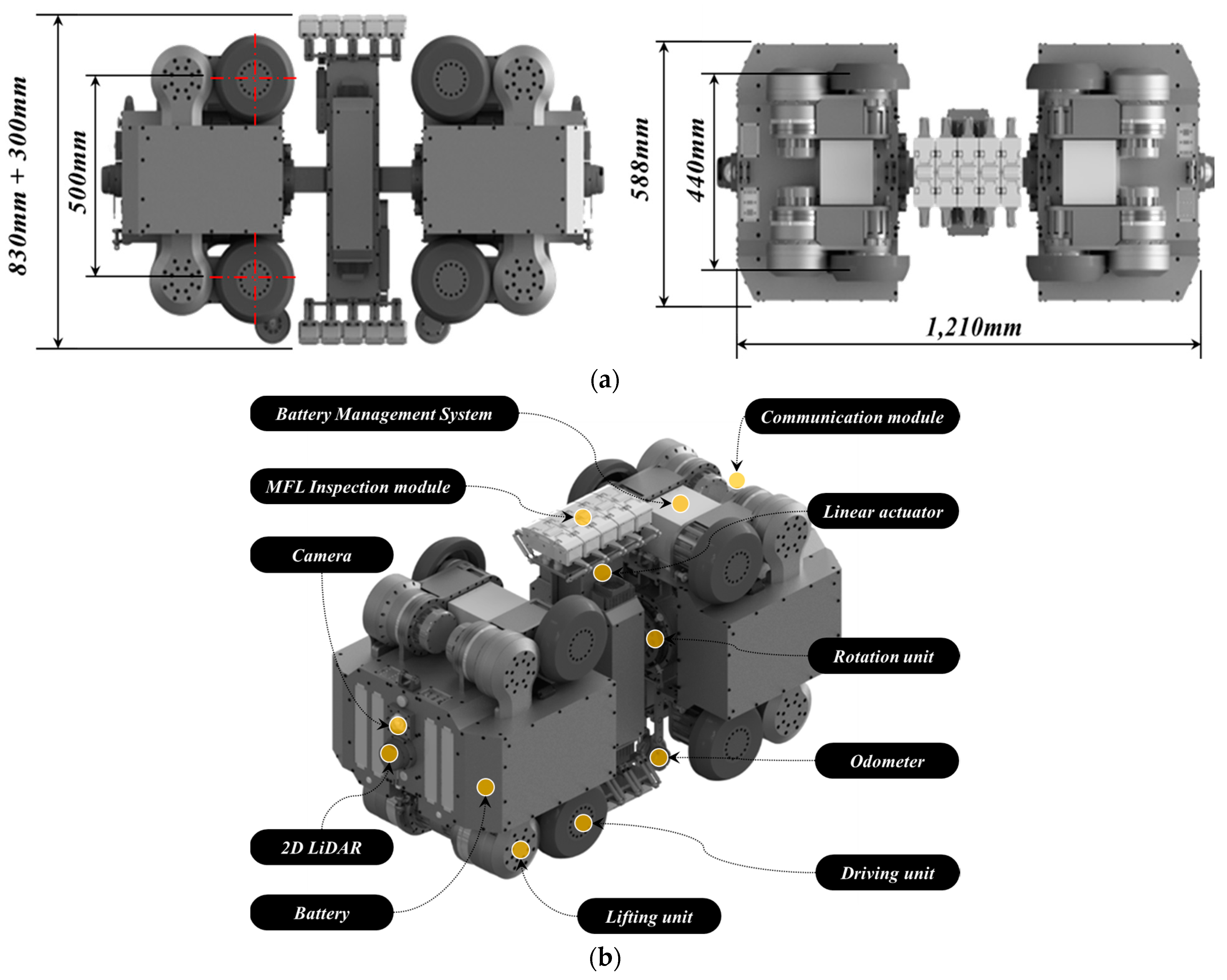
2.2. Composition of In-Pipe Inspection Robot
- Driving Parts: Each driving segment includes four lifting arms and four driving units. The lifting arms are designed to adjust the robot’s position, ensuring it remains centered within the pipe during the inspection process. The driving units facilitate the robot’s movement through the pipe. To monitor the internal conditions of the pipe and assess the robot’s positioning, each driving part is equipped with a camera module and a 2D LiDAR sensor. The rear driving module features a wireless communication module for external communications. The distance traveled by the robot is measured by odometers attached to the bottom of each driving part. Additionally, an Attitude and Heading Reference System (AHRS) sensor is installed to monitor the yaw, roll, and pitch angle variations of the driving parts.
- Inspection Part: This component is capable of rotating around the pipe’s circumference via a rotation unit, allowing for a thorough circumferential inspection. A linear actuator is integrated to accommodate varying pipe diameters, ensuring compatibility across the specified range. The MFL inspection module, positioned at both ends of the inspection part, includes five inspection units, each equipped with seven Hall sensor modules. This arrangement facilitates comprehensive assessment of the pipe’s condition.
2.3. Design of In-Pipe Inspection Robot
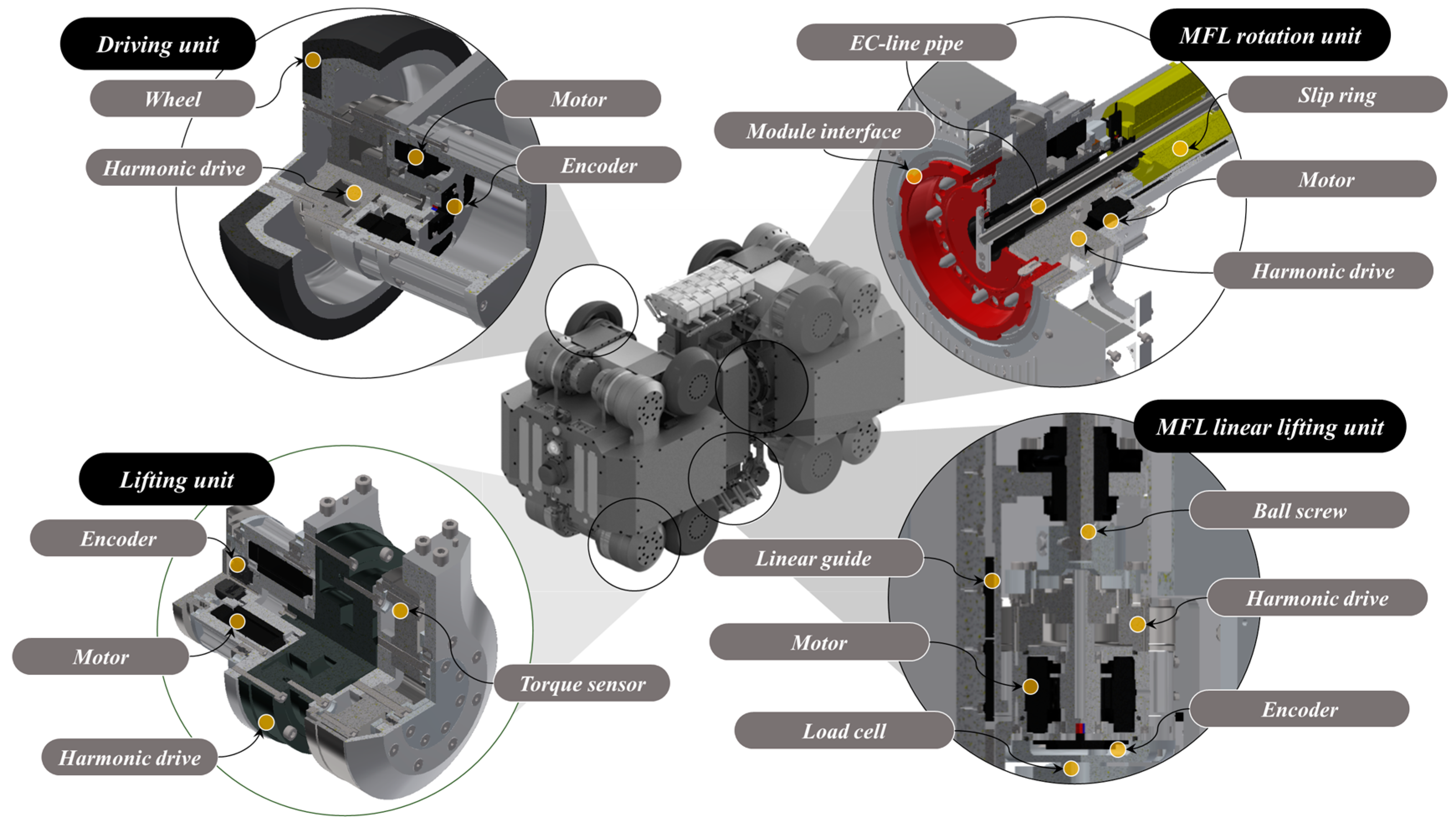
- Driving Units: The robot’s driving module features driving units constructed from urethane wheels mounted on an aluminum base, powered by rotation motors. These units are further equipped with harmonic drives and encoders to ensure precise movement and control.
- Lifting Units: Integral to adjusting the robot’s vertical position, the lifting units consist of rotation motors, encoders, harmonic drives, and torque sensors. This setup enables the robot to maintain its central alignment within the pipe, which is crucial to an accurate inspection.
- MFL Rotation and Lifting Units: The design incorporates a hollow structure for the MFL rotation unit, facilitating the passage of communication and power lines, with a slip ring ensuring uninterrupted communication with the driving modules. It includes a rotation motor and a harmonic drive for efficient rotational movement. The MFL lifting unit is designed for vertical extension up to 150 mm, accommodating pipes of various diameters. It comprises a rotation motor, harmonic drive, linear guide, ball screw, and load cell for precise control and force measurement.
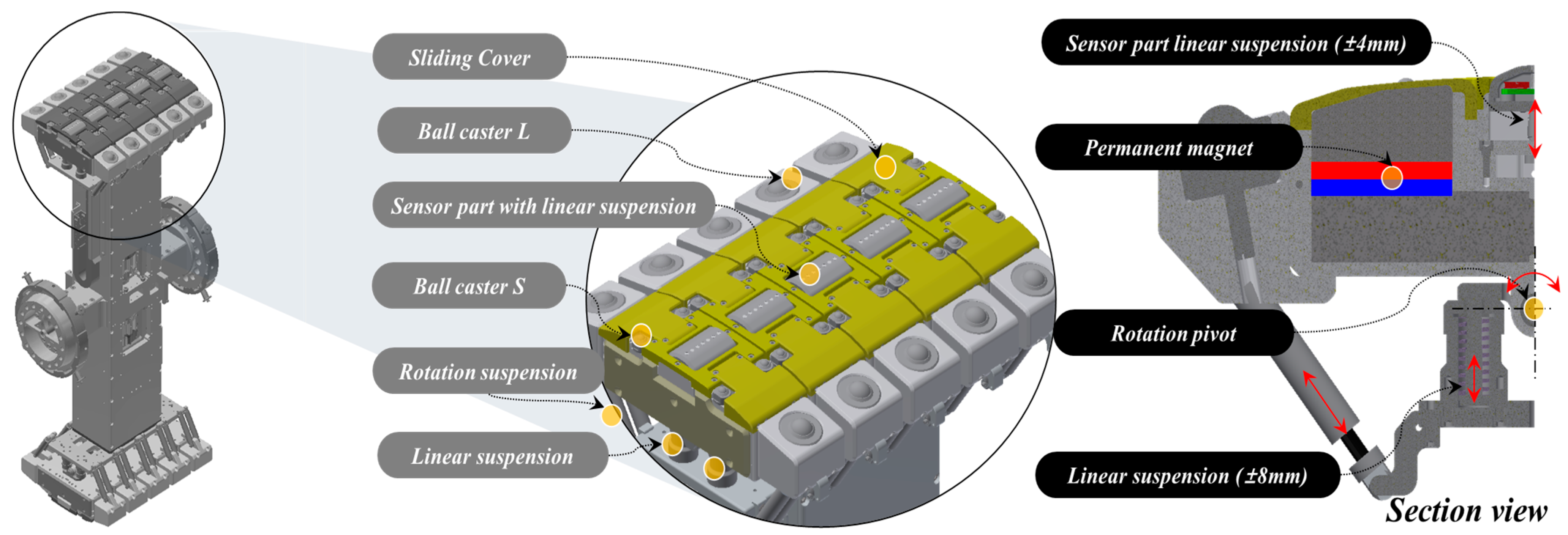
- MFL Inspection Modules: To inspect the defects in pipelines, the in-pipe inspection robot has two inspection modules. These modules measure MFL using permanent magnets and Hall sensors. The inspection modules are located at the central ends of the robot. The inspection modules located at each end consist of five independent inspection units. Each inspection unit is equipped with seven Hall sensor modules. One Hall sensor module comprises seven Hall sensors, hence, one inspection module contains a total of 35 Hall sensors. The inspection units applied to the inspection modules come into contact with the pipeline and rotate. During this rotation, the gap distance between the pipeline and the inspection unit affects the inspection quality. To maintain a constant gap distance between the pipeline and the inspection unit, a rotation/suspension mechanism is applied. Furthermore, to reduce the vibration of the MFL inspection module rotating while in contact with the inner surface of the pipeline, individual inspection units are equipped with rotation pivots and suspensions. The pipeline and inspection units rotate with low friction using ball casters. A mechanism capable of linear height adjustment is applied to the sensor part where the Hall sensors are located to maintain a constant distance from the inspected pipeline. Ceramic tips are applied to the end of the sensor module that contacts the pipeline to minimize wear. This design of the inspection module minimizes noise caused by vibration, a drawback of the MFL inspection method performed while in contact with the pipeline, and ensures a constant gap distance between the pipeline and the permanent magnets, resulting in high-quality inspection results.
3. Control of In-Pipe Inspection Robot
3.1. Control of Driving Wheel
3.2. Control of Odometer Arm
3.3. Control of Driving Lifting Unit for the Driving Wheels
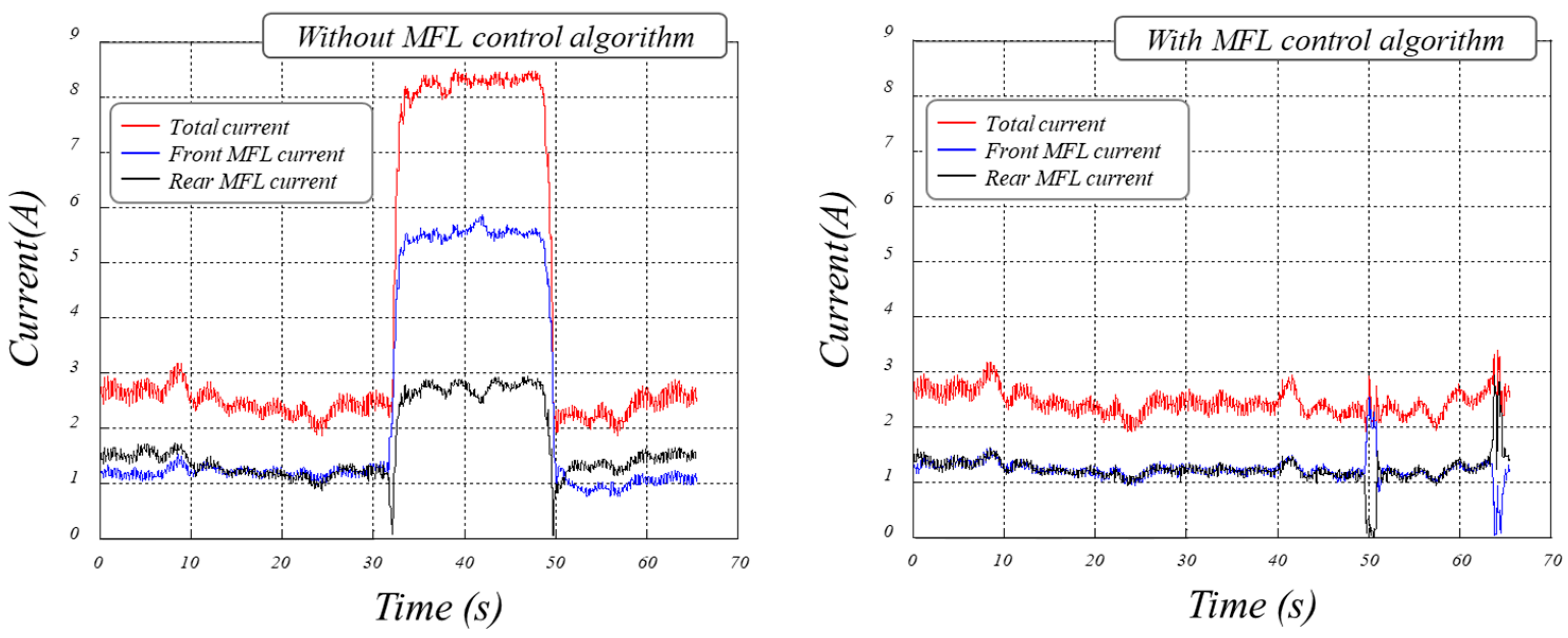
3.4. Control of MFL Inspection Module
3.5. Control of MFL Inspection Module Lifts
3.6. Posture Control of In-Pipe Inspection Robot
3.6.1. Pitch Control of the In-Pipe Inspection Robot
3.6.2. Roll Control of the In-Pipe Inspection Robot
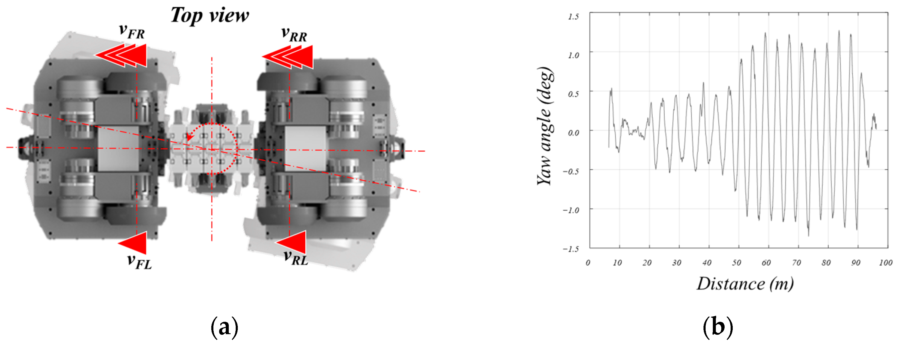
3.6.3. Yaw Control of the In-Pipe Inspection Robot
4. Field Testing of In-Pipe Inspection Robot
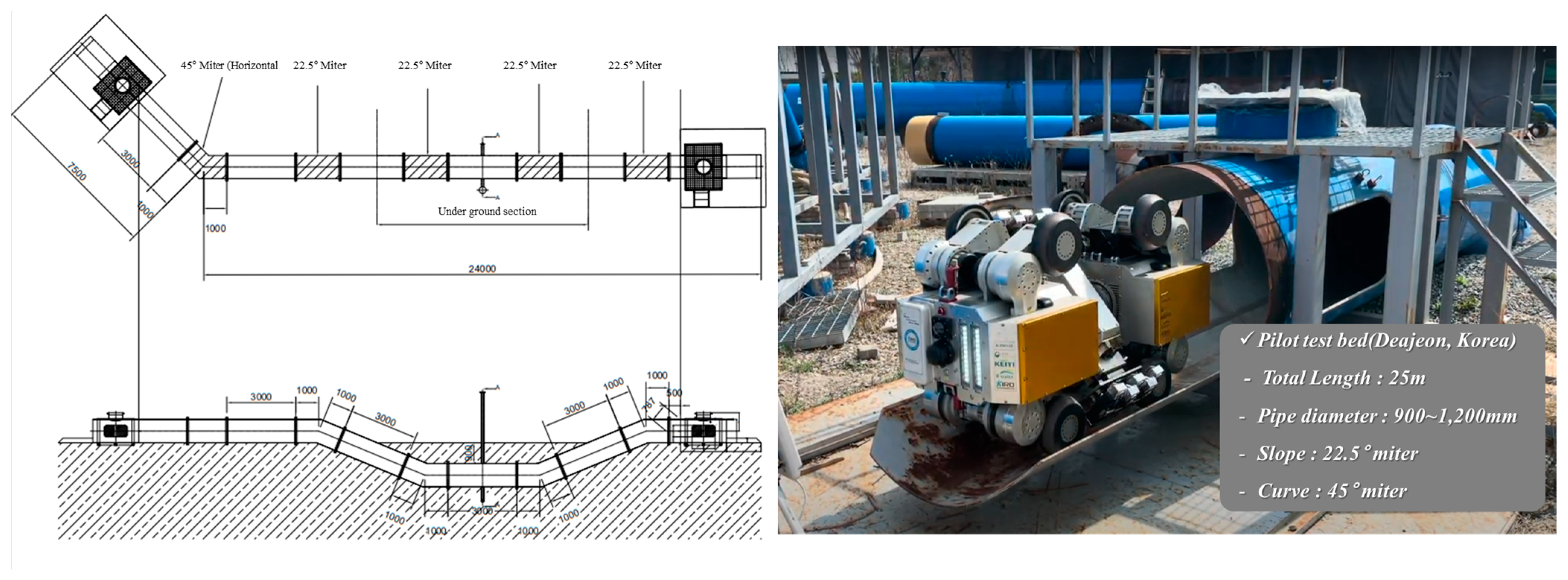
4.1. Configuration of the Field Test Bed
4.2. Results of Driving Test of In-Pipe Inspection Robot at Field Test Bed
5. Discussion
6. Conclusions
Author Contributions
Funding
Institutional Review Board Statement
Informed Consent Statement
Data Availability Statement
Acknowledgments
Conflicts of Interest
References
- Kim, E.-S.; Lee, S.-H.; Yoon, K.-Y. Assessment of the Deterioration of Large-Diameter Pipe Networks (I): Development of an Assessment Model. J. Korea Acad.-Ind. Coop. Soc. 2014, 15, 482–487. [Google Scholar]
- Lee, S.-H.; Yoon, K.-Y.; Kim, E.-S. Assessment of the Deterioration of Large-Diameter Pipe Networks (II): Application to Metropolitan Multi-Regional Water Supply System (1st Phase). J. Korea Acad.-Ind. Coop. Soc. 2014, 15, 1096–1101. [Google Scholar]
- Tonge, M.P.; Gilbert, R.G. Testing models for penetrant diffusion in glassy polymers. Polymer 2001, 42, 501–513. [Google Scholar] [CrossRef]
- Zheng, S.; Vanderstelt, J.; McDermid, J.R.; Kish, J.R. Non-destructive investigation of aluminum alloy hemmed joints using neutron radiography and X-ray computed tomography. NDT E Int. 2017, 91, 32–35. [Google Scholar] [CrossRef]
- Berger, H. Advances in neutron radiographic techniques and applications: A method for nondestructive testing. Appl. Radiat. Isot. 2004, 61, 437–442. [Google Scholar] [CrossRef] [PubMed]
- Haupert, S.; Guillaume, R.; Andreas, S. Ultrasonic imaging of nonlinear scatterers buried in a medium. NDT E Int. 2017, 87, 1–6. [Google Scholar] [CrossRef]
- Ravanbod, H. Application of neuro-fuzzy techniques in oil pipeline ultrasonic nondestructive testing. NDT E Int. 2005, 38, 643–653. [Google Scholar] [CrossRef]
- Bettayeb, F.; Haciane, S.; Aoudia, S. Improving the time resolution and signal noise ratio of ultrasonic testing of welds by the wavelet packet. NDT E Int. 2005, 38, 478–484. [Google Scholar] [CrossRef]
- Park, J.H.; Kim, H.M.; Park, G.S. A study on the signal correction for multiple defects in MFL type nondestructive testing system. J. Korean Magn. Soc. 2016, 26, 24–30. [Google Scholar] [CrossRef]
- Ahn, B.-Y.; Kim, Y.-J.; Kim, Y.-G.; Lee, S.-S. Development of an EMAT system for detecting flaws in pipeline. J. Korean Soc. Nondestruct. Test. 2004, 24, 15–21. [Google Scholar]
- Liu, X.; Hu, C.; Peng, P.; Li, R.; Zhao, X.; Zheng, D. In-pipe Detection System Based on Magnetic Flux Leakage and Eddy Current Detection. In Proceedings of the International Conference on Sensing, Measurement & Data Analytics in the era of Artificial Intelligence (ICSMD) IEEE, Xi’an, China, 15–17 October 2020. [Google Scholar]
- Andrews, M.E.; Eng, P. Large diameter sewer condition assessment using combined sonar and CCTV equipment. In Proceedings of the APWA International Public Works Congress, Las Vegas, NV, USA, 14–17 September 1998. [Google Scholar]
- Mohammed, M.N.; Nadarajah, V.S.; Lazim, N.F.M.; Zamani, N.S.; Al-Sanjary, O.I.; Ali, M.A.; Al-Youif, S. Design and development of pipeline inspection robot for crack and corrosion detection. In Proceedings of the 2018 IEEE Conference on Systems, Process and Control (ICSPC 2018), Melaka, Malaysia, 14–15 December 2018. [Google Scholar]
- Kim, H.M.; Yoo, H.R.; Park, G.S. A new design of MFL sensors for self-driving NDT robot to avoid getting stuck in curved underground pipelines. IEEE Trans. Magn. 2018, 54, 6202705. [Google Scholar] [CrossRef]
- Pasha, M.A.; Khan, T.M. A pipeline inspection gauge based on low cost magnetic flux leakage sensing magnetometers for non-destructive testing of pipelines. In Proceedings of the 2016 International Conference on Emerging Technologies (ICET), Islamabad, Pakistan, 18–19 October 2016; IEEE: New York, NY, USA, 2016. [Google Scholar]
- Park, J.J.; Moon, J.W.; Kim, H.; Jang, S.C.; Kim, D.G.; Ahn, K.; Ryew, S.M.; Moon, H.; Choi, H.R. Development of the untethered in-pipe inspection robot for natural gas pipelines. In Proceedings of the 10th International Conference on Ubiquitous Robots and Ambient Intelligence (URAI), Jeju, Republic of Korea, 30 October–2 November 2013. [Google Scholar]
- Burkett, S.; Schempf, H. Wireless self-powered visual and NDE robotic inspection system for live gas distribution mains. In Proceedings of the Topical Report; The Department of Energy (DoE), National Energy Technology Laboratory (NETL), Carnegie Mellon Univ.: Pittsburgh, PA, USA, 31 January 2006. [Google Scholar]
- Kim, Y.G.; Shin, D.H.; Moon, J.I.; An, J. Design and implementation of an optimal in-pipe navigation mechanism for a steel pipe cleaning robot. In Proceedings of the 8th International Conference on Ubiquitous Robots and Ambient Intelligence (URAI 2011), Incheon, Korea, 23–26 November 2011. [Google Scholar]
- Mateos, L.A.; Kai, Z.; Vincze, M. Towards e_cient pipe maintenance: DeWaLoP in-pipe robot stability controller. In Proceedings of the 2012 IEEE International Conference on Mechatronics and Automation (ICMA), Chengdu, China, 5–8 August 2012. [Google Scholar]
- Mateos, L.A.; Dominguez, M.R.Y.; Vincze, M. Automatic In-pipe Robot Centering from 3D to 2D Controller Simplification. In Proceedings of the 2013 Ieee/Rsj International Conference on Intelligent Robots and Systems, Tokyo, Japan, 3–7 November 2013. [Google Scholar]
- Zhao, W.; Zhang, L.; Kim, J.W. Design and Analysis of Independently Adjustable Large In-Pipe Robot for Long-Distance Pipeline. Appl. Sci. 2020, 10, 3637. [Google Scholar] [CrossRef]
- Yan, X.; Zhang, D.; Pan, S.; Zhang, E.; Gao, W. Online nondestructive testing for fine steel wire rope in electromagnetic interference environment. NDT E Int. 2017, 92, 75–81. [Google Scholar] [CrossRef]
- Kim, H.M.; Park, G.S. A Study on the estimation of the shapes of axially oriented cracks in CMFL type NDT system. IEEE Trans. Magn. 2014, 50, 109–112. [Google Scholar] [CrossRef]
- Kim, H.M.; Heo, C.G.; Cho, S.H.; Park, G.S. Determination Scheme for Accurate Defect Depth in Underground Pipeline Inspection by Using Magnetic Flux Leakage Sensors. IEEE Trans. Magn. 2018, 54, 6202805. [Google Scholar] [CrossRef]
- Peng, X.; Anyaoha, U.; Liu, Z. Analysis of Magnetic-Flux Leakage (MFL) Data for Pipeline Corrosion Assessment. IEEE Trans. Magn. 2015, 56, 6200315. [Google Scholar] [CrossRef]
- Feng, J.; Zhang, X.; Lu, S. A Single—Stage Enhancement-Identification Framework for Pipeline MFL Inspection. IEEE Trans. Instrum. Meas. 2022, 71, 3513813. [Google Scholar] [CrossRef]
- Fenyvesi, L.L.; Colquhoun, I.; Kania, R.; Gu, B. NDE Techniques for Reliable Inspection of Carbon Steel Tubes. In Proceedings of the International Pipeline Conference, Calgary, AB, Canada, 4–8 October 2004. [Google Scholar]
- Feng, J.; Liu, J.; Zhang, H. Speed Control of Pipeline Inner Detector Based on Interval Dynamic Matrix Control with Additional Margin. IEEE Trans. Ind. Electron. 2021, 71, 12657–12667. [Google Scholar] [CrossRef]
- Zhang, Y.; Ye, Z.; Xu, X. An adaptive method for channel equalization in MFL inspection. NDT E Int. 2007, 40, 127–139. [Google Scholar] [CrossRef]
- Salama, M.M.; Nestleroth, B.J.; Maes, M.A.; Rodriguez, C.; Blumer, D. Characterization of the Accuracy of the MFL Pipeline Inspection Tools. In Proceedings of the International Conference on Ocean, Offshore, and Arctic Engineering (OMAE), Nantes, France, 23 August 2013. [Google Scholar]
- Pham, H.Q.; Trinh, Q.T.; Doan, D.T.; Tran, Q.H. Importance of Magnetizing Field on Magnetic Flux Leakage Signal of Defects. IEEE Trans. Magn. 2018, 54, 6201206. [Google Scholar] [CrossRef]
- Pham, H.Q.; Tran, B.V.; Doan, D.T.; Le, V.S.; Pham, Q.N.; Kim, K.; Kim, C.; Terki, F.; Tran, Q.H. Highly Sensitive Planar Hall Magnetoresistive Sensor for Magnetic Flux Leakage Pipeline Inspection. IEEE Trans. Magn. 2018, 54, 6201105. [Google Scholar] [CrossRef]
- Muhammad, A.; Jae-Joon, K.; Satish, U.; Lalita, U.; William, L. Enhancement and Detection of Mechanical Damage MFL Signals from Gas Pipeline Inspection. Rev. Prog. Quant. Nondestruct. Eval. 1999, 18, 805–812. [Google Scholar]
- Lord, W.; Udpa, S.; Udpa, L.; Afzal, M.; Ivanov, P.; Yang, S. Materials characterization challenges for MFL pipeline inspection. AIP Conf. Proc. 1999, 497, 189–195. [Google Scholar]
- Kim, D.-K.; Yoo, H.-R.; Yoo, J.-S.; Kim, D.-K.; Cho, S.-H.; Koo, S.-J.; Woo, R.-Y.; Jung, H.-K. Development of MFL system for In-pipe Robot for Unpiggable Natural Gas Pipelines. In Proceedings of the 10th International Conference on Ubiquitous Robots and Ambient Intelligence (URAI), Jeju, Republic of Korea, 30 October–2 November 2013. [Google Scholar]
- Korean Standards Association. KS D 3578: Fittings of Coated Steel Pipes for Water Works. 2015. Available online: https://www.standard.go.kr/KSCI/ (accessed on 23 May 2024).


| Index | Pipe No. | Position (m) | Angle (°) | Thickness (mm) |
|---|---|---|---|---|
| 1 | 32 | 256.54 | 260.9 | 7.92 |
| 2 | 37 | 278.46 | 252.6 | 7.97 |
| 3 * | 52 | 346.28 | 285.5 | 5.17 |
| 4 * | 52 | 365.91 | 270.2 | 6.64 |
| 5 | 79 | 525.37 | 276.6 | 7.03 |
| 6 | 80 | 529.11 | 299.5 | 7.97 |
| 7 | 105 | 674.18 | 274.9 | 7.86 |
| 8 * | 149 | 925.52 | 296.8 | 4.08 |
| 9 * | 155 | 978.17 | 329.8 | 6.19 |
| 10 | 155 | 980.28 | 322.3 | 7.29 |
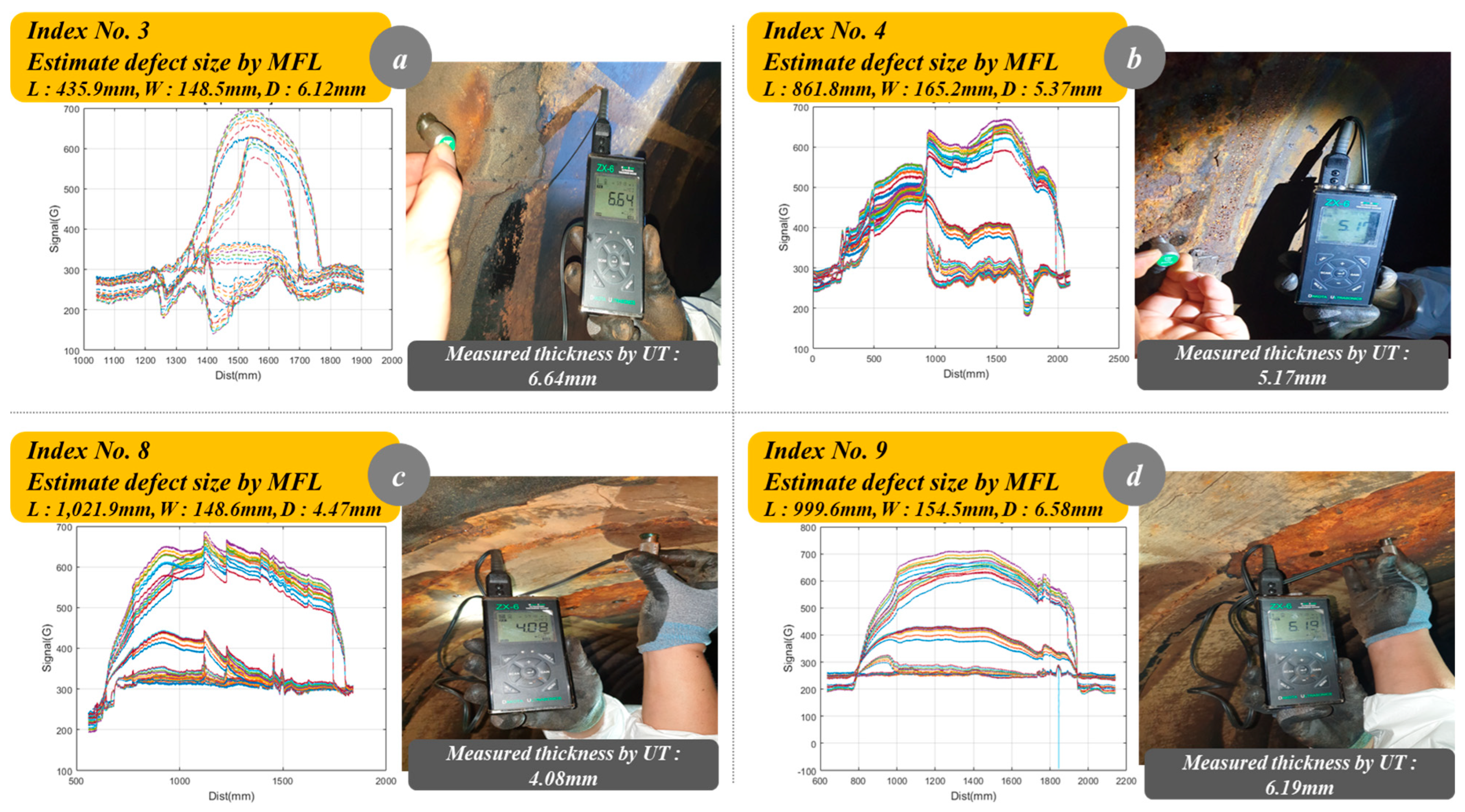
| Index | Estimated Defect Value (MFL Inspection) | Measured Thickness by Ultrasonic (mm) | Error (%) | ||
|---|---|---|---|---|---|
| L (mm) | W (mm) | T (mm) | |||
| 3 | 435.9 | 148.5 | 6.12 | 6.64 | 8.49 |
| 4 | 861.8 | 165.2 | 5.37 | 5.17 | 3.72 |
| 8 | 1021.9 | 148.6 | 4.47 | 4.08 | 8.91 |
| 9 | 999.6 | 154.5 | 6.58 | 6.19 | 5.92 |
Disclaimer/Publisher’s Note: The statements, opinions and data contained in all publications are solely those of the individual author(s) and contributor(s) and not of MDPI and/or the editor(s). MDPI and/or the editor(s) disclaim responsibility for any injury to people or property resulting from any ideas, methods, instructions or products referred to in the content. |
© 2024 by the authors. Licensee MDPI, Basel, Switzerland. This article is an open access article distributed under the terms and conditions of the Creative Commons Attribution (CC BY) license (https://creativecommons.org/licenses/by/4.0/).
Share and Cite
Jeon, K.-W.; Jung, E.-J.; Bae, J.-H.; Park, S.-H.; Kim, J.-J.; Chung, G.; Chung, H.-J.; Yi, H. Development of an In-Pipe Inspection Robot for Large-Diameter Water Pipes. Sensors 2024, 24, 3470. https://doi.org/10.3390/s24113470
Jeon K-W, Jung E-J, Bae J-H, Park S-H, Kim J-J, Chung G, Chung H-J, Yi H. Development of an In-Pipe Inspection Robot for Large-Diameter Water Pipes. Sensors. 2024; 24(11):3470. https://doi.org/10.3390/s24113470
Chicago/Turabian StyleJeon, Kwang-Woo, Eui-Jung Jung, Jong-Ho Bae, Sung-Ho Park, Jung-Jun Kim, Goobong Chung, Hyun-Joon Chung, and Hak Yi. 2024. "Development of an In-Pipe Inspection Robot for Large-Diameter Water Pipes" Sensors 24, no. 11: 3470. https://doi.org/10.3390/s24113470
APA StyleJeon, K.-W., Jung, E.-J., Bae, J.-H., Park, S.-H., Kim, J.-J., Chung, G., Chung, H.-J., & Yi, H. (2024). Development of an In-Pipe Inspection Robot for Large-Diameter Water Pipes. Sensors, 24(11), 3470. https://doi.org/10.3390/s24113470