
An Automatic Method for Elbow Joint Recognition, Segmentation and Reconstruction
Abstract
1. Introduction
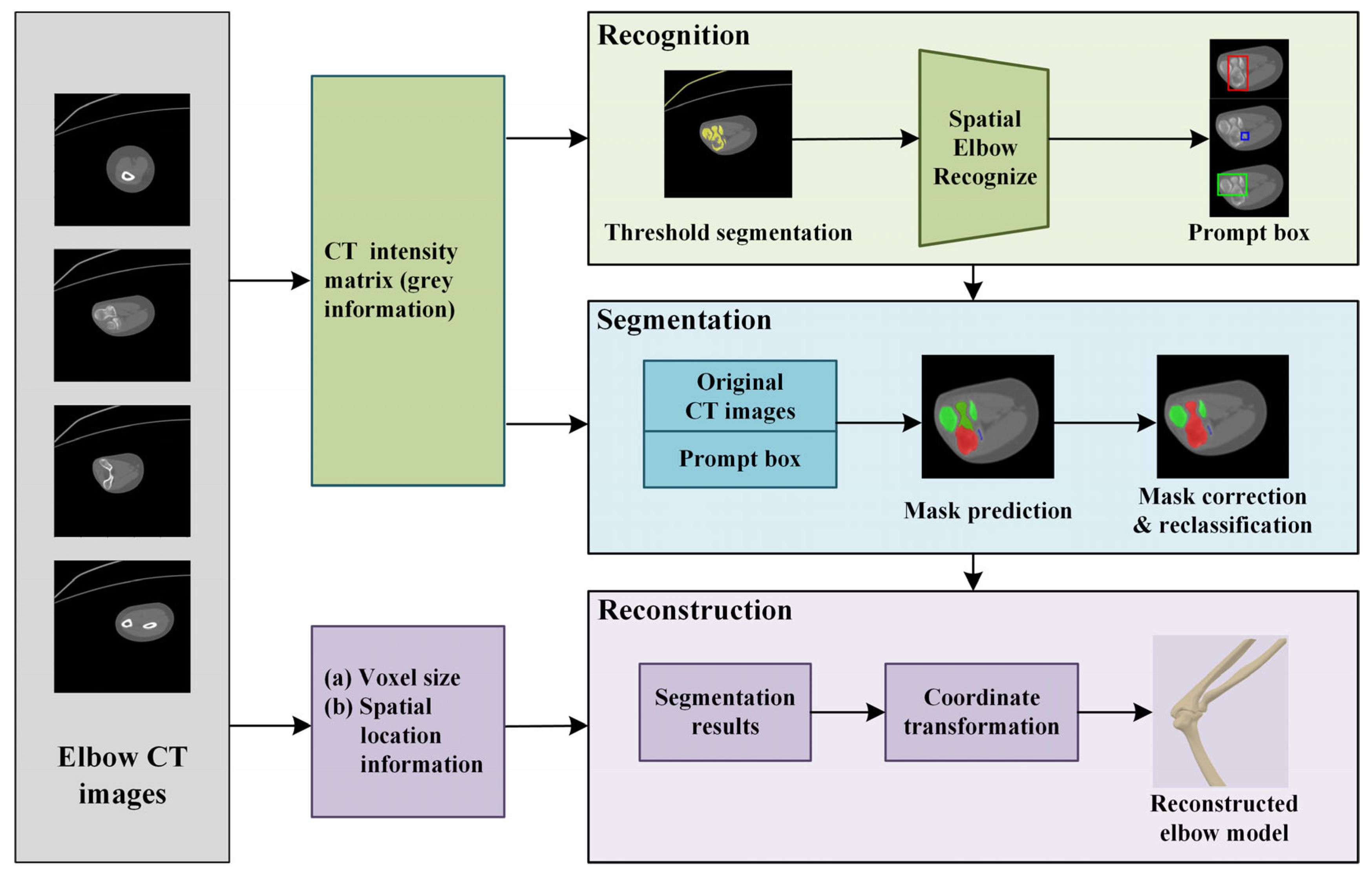
2. Method
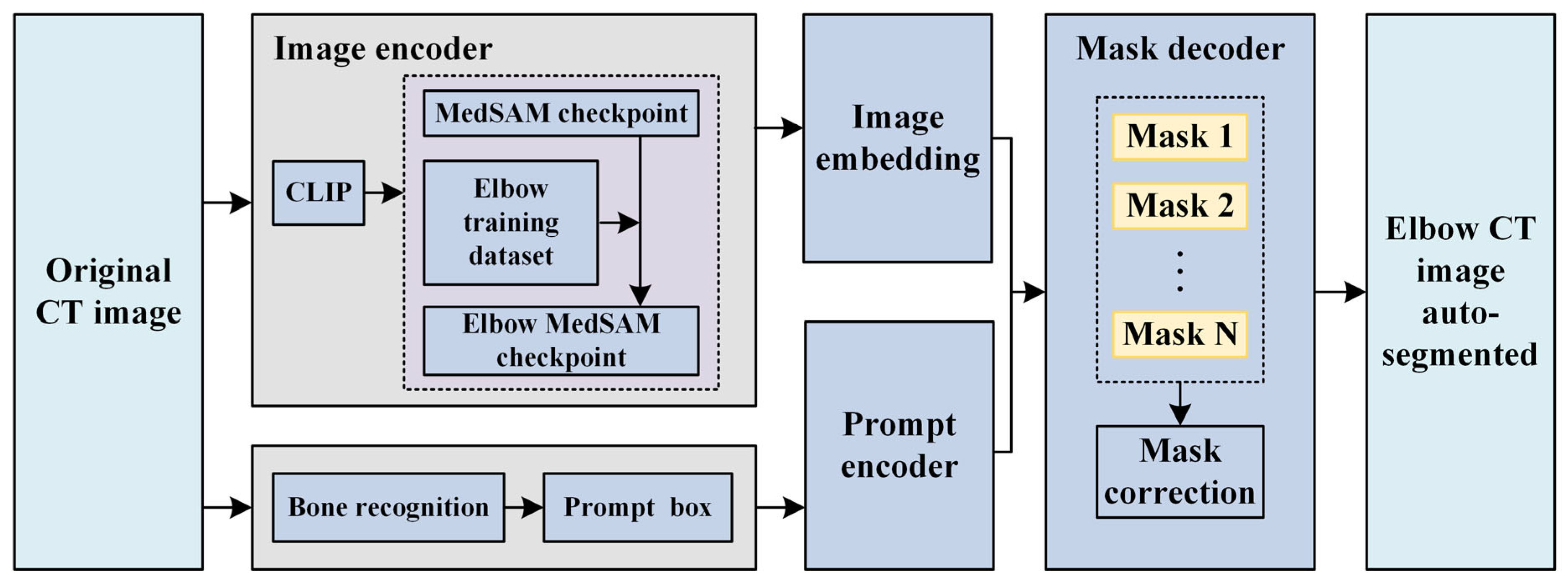
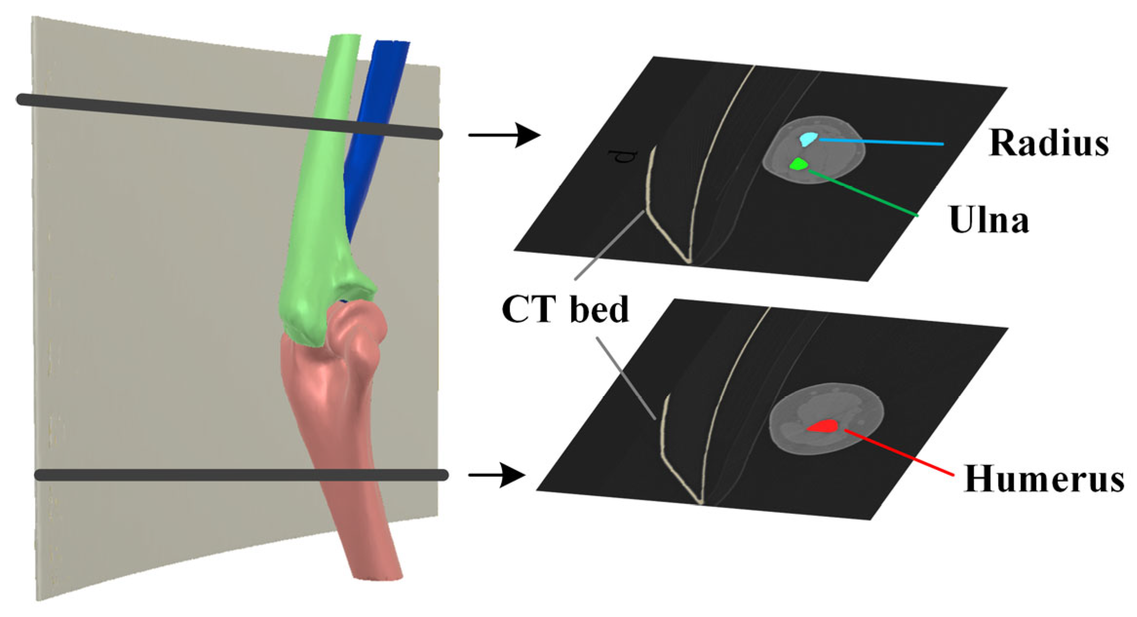
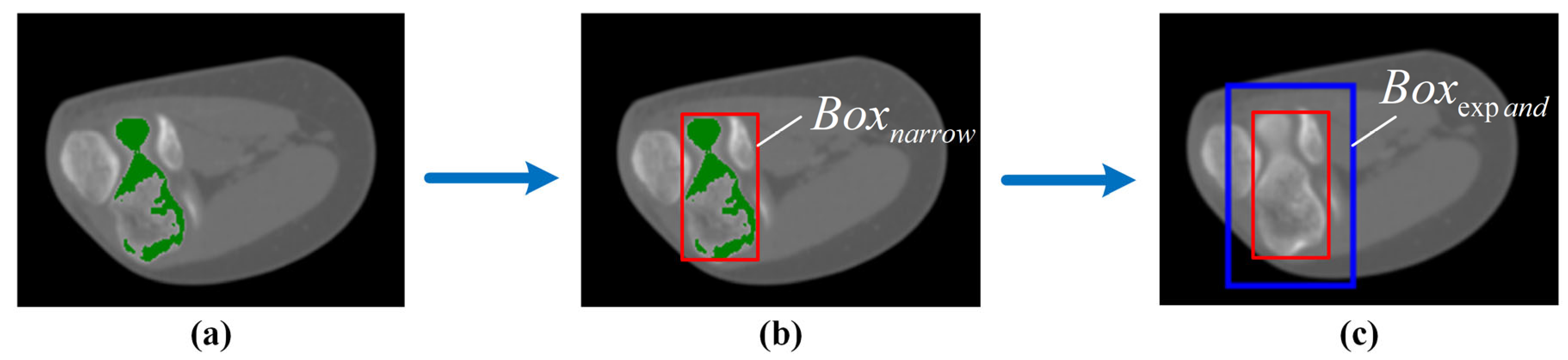
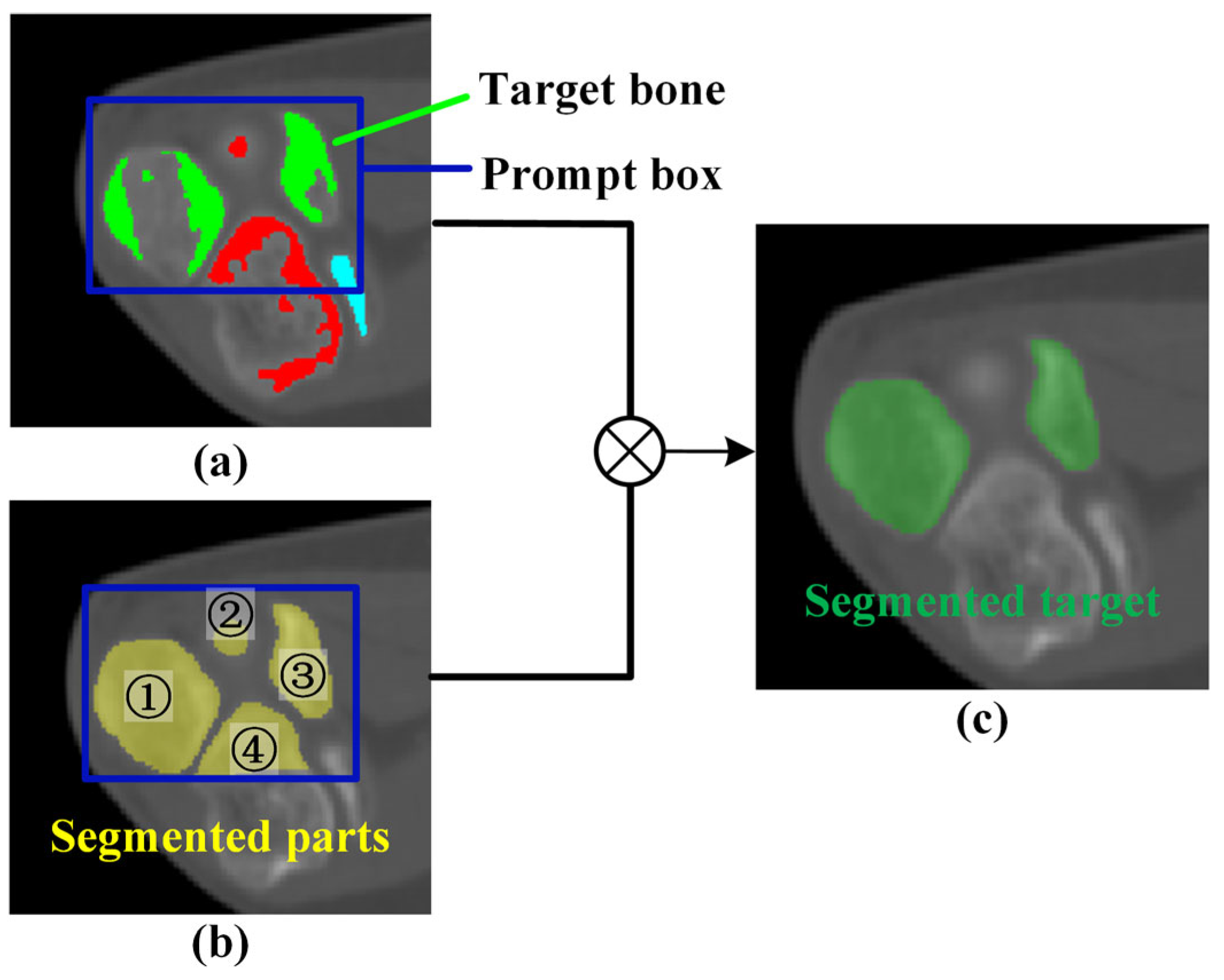
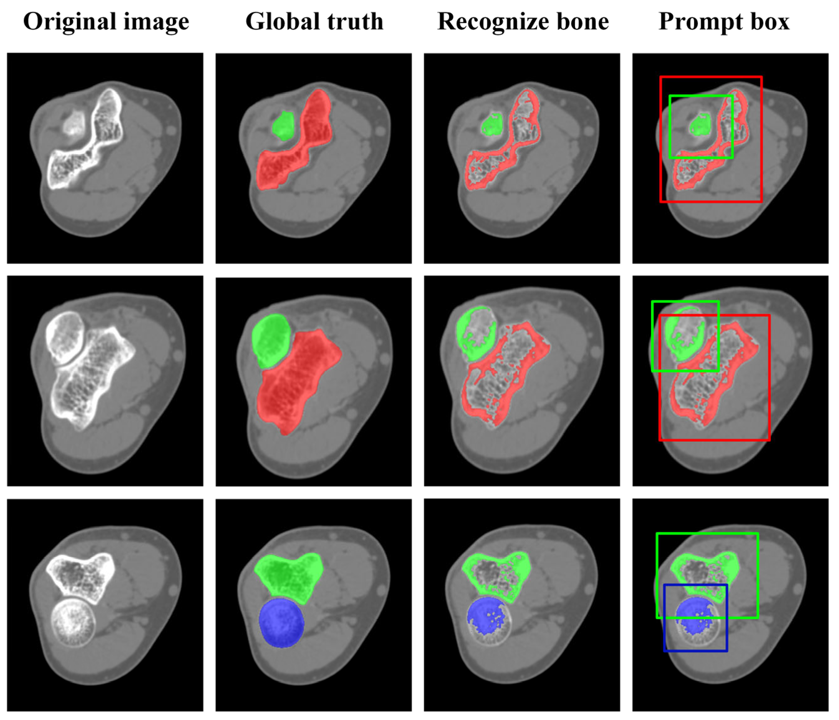
2.1. Original Elbow CT Image Segmentation
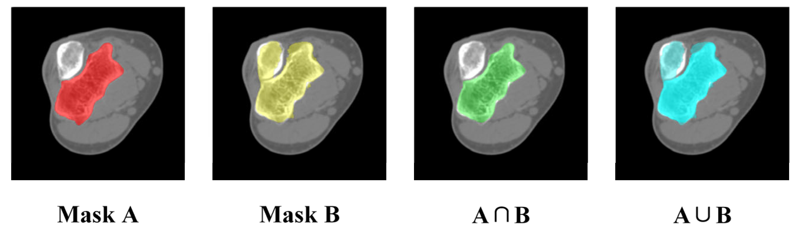
2.2. Mask Correction and Reclassification
2.3. Elbow Reconstruction
3. Results and Discussion
3.1. Dataset
3.2. Verification of Elbow Bone Recognition
3.2.1. Result of Elbow Bone Recognition
3.2.2. Impact of Automatic Prompt Box Generation
3.3. Impact of Mask Correction and Reclassification
3.4. Result of Elbow CT Segmentation
3.4.1. Qualitative Evaluation of Segmentation Results
3.4.2. Quantitative Evaluation of Segmentation Accuracy
3.4.3. Objectivity Discussion of Elbow Joint Segmentation
3.5. Reliability and Accuracy of 3D Elbow Reconstruction
3.5.1. Result of 3D Elbow Reconstruction
3.5.2. Reliability Analysis of Elbow Joint Reconstruction
4. Conclusions
- (1)
- This study employs an interpretable algorithm to automatically recognize the humerus, ulna, and radius from elbow joint CT images. The algorithm exhibits stability and effectiveness for elbow joints from flexion (82.10°) to extension (170.11°) postures.
- (2)
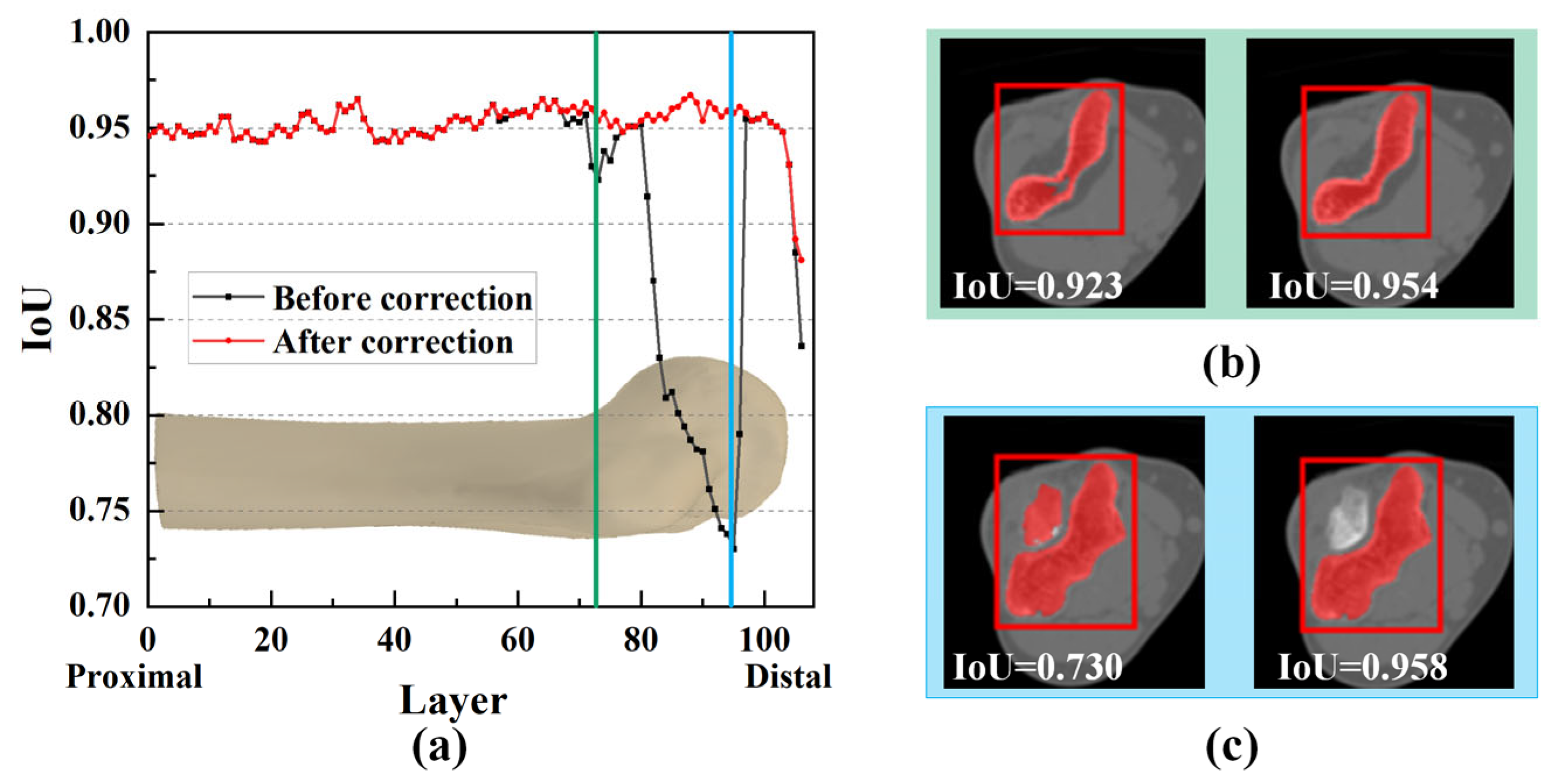
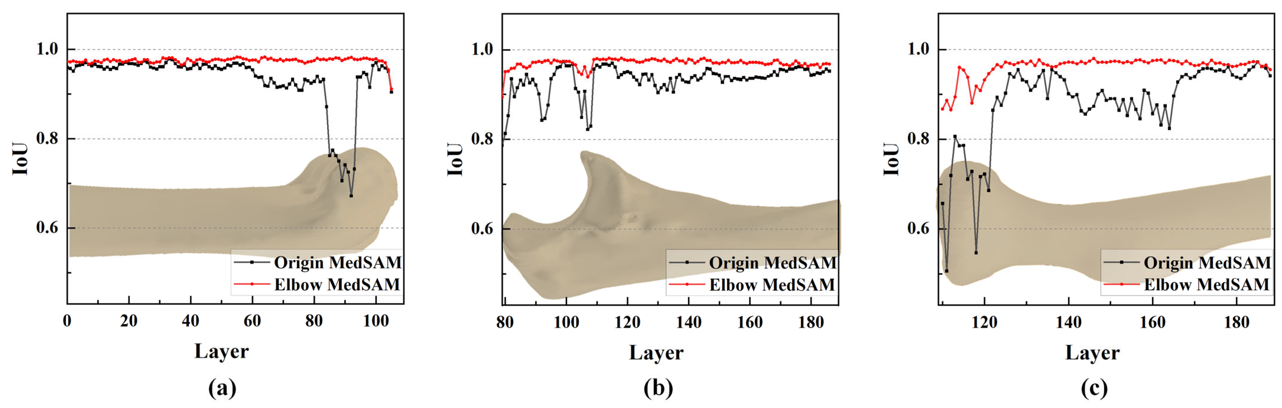
- The IoU values near the joint are significantly increased by mask correction and reclassification, with a maximum improvement of 0.028, conclusively boosting segmentation accuracy.
- (3)
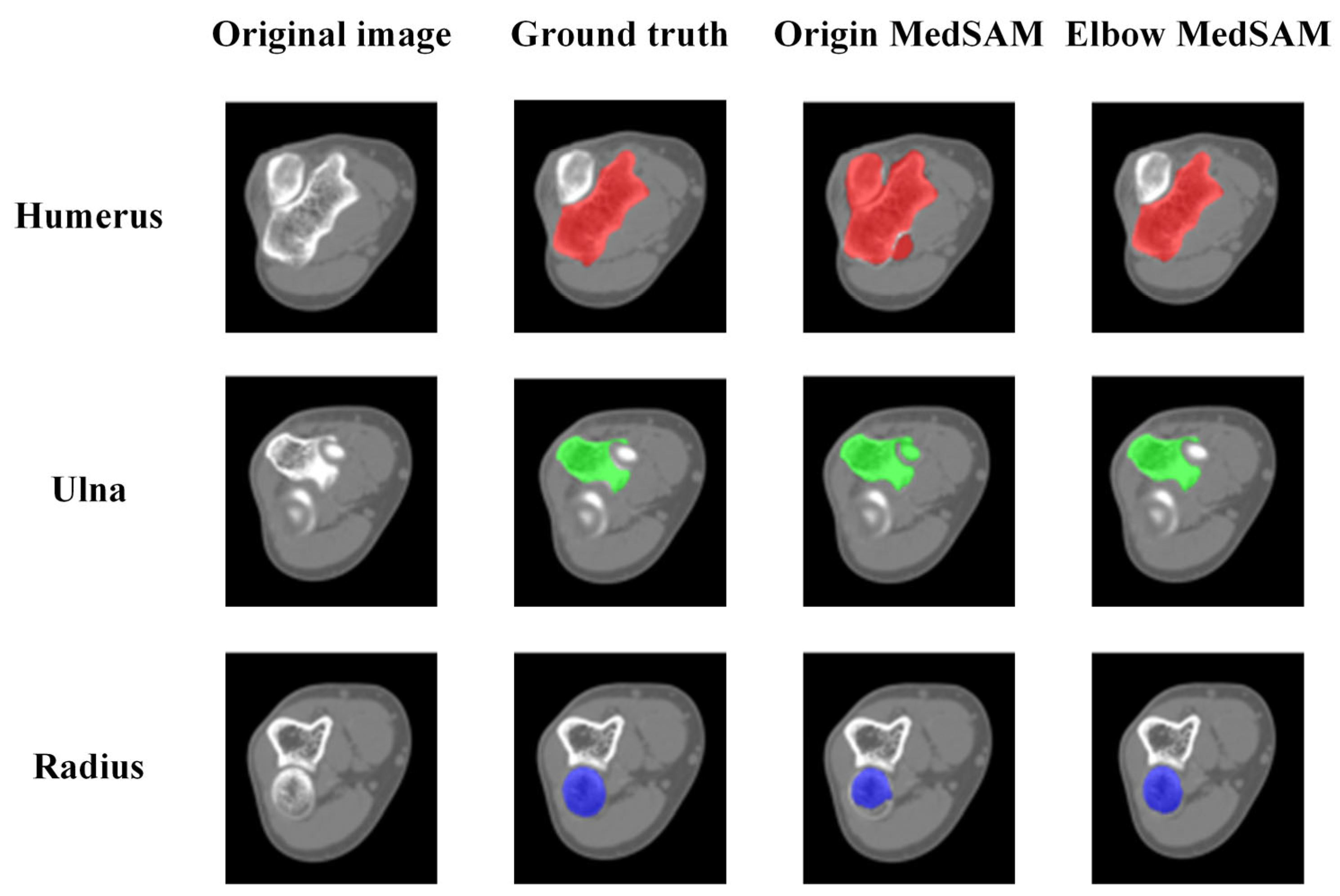
- The segmentation accuracy is enhanced by the MedSAM after transfer learning, allowing for more precise capture of bone edges and reducing instances of mistaking multiple bones as a single target. The median IoU values are 0.963, 0.959, and 0.950 for the humerus, ulna, and radius, respectively, notably surpassing the predictions of the origin MedSAM.
- (4)
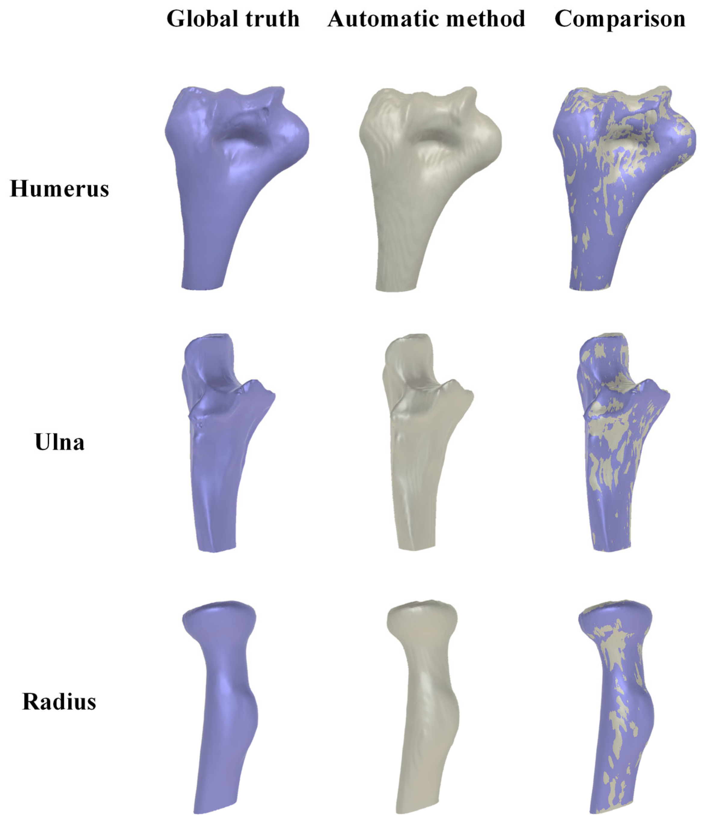
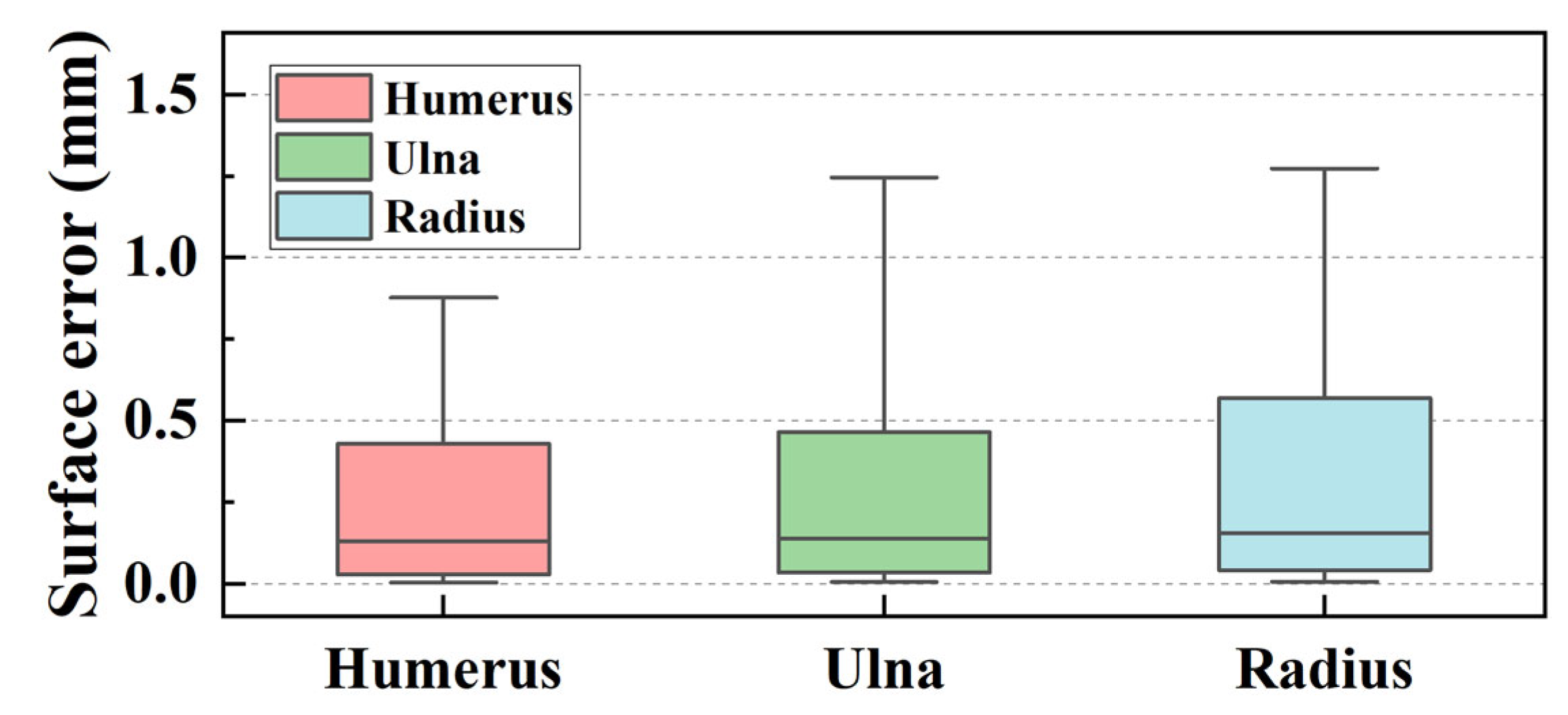
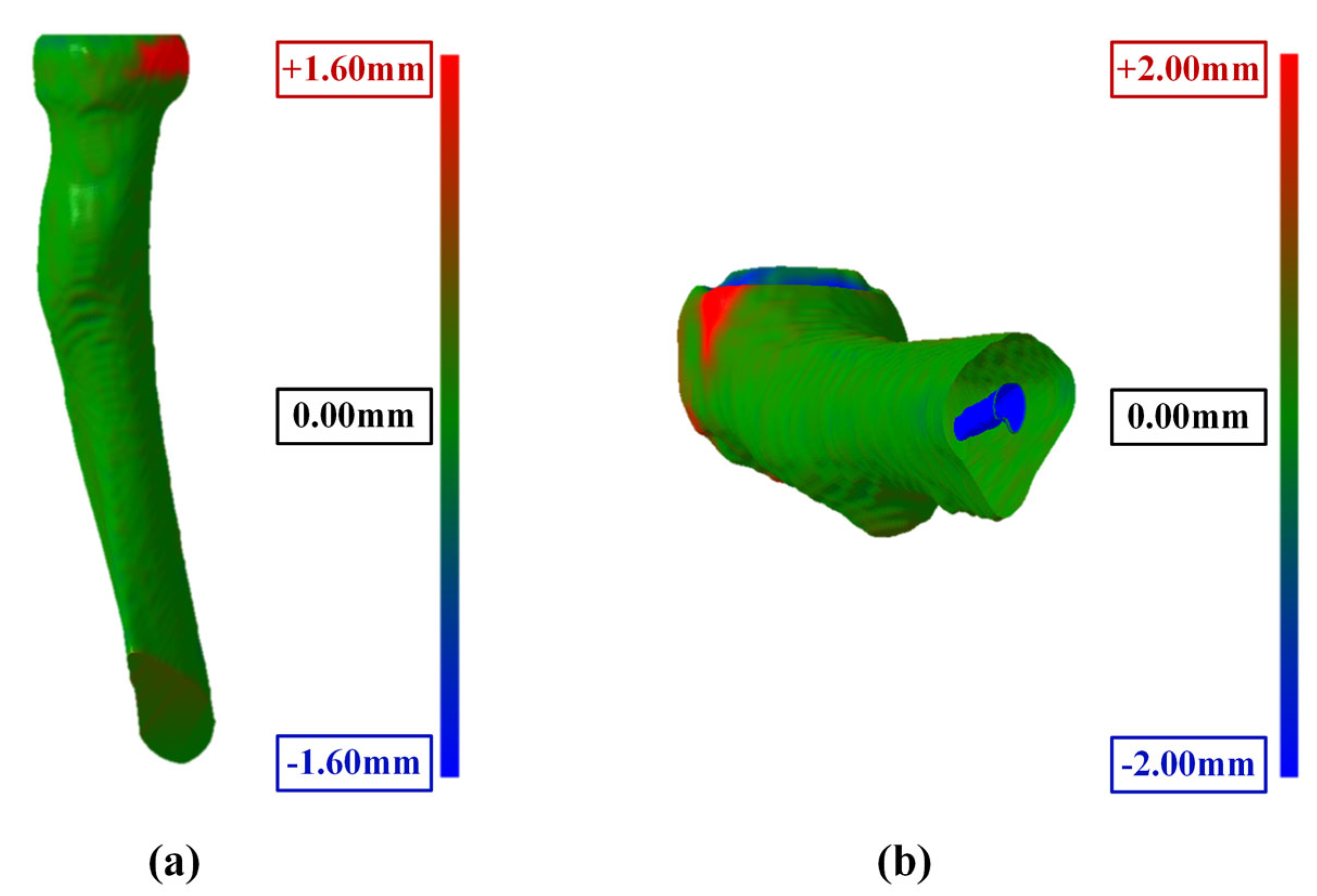
- The maximum surface errors for the bone surface model reconstructed by the marching cube algorithm are 1.127, 1.523, and 2.062 mm for the humerus, ulna, and radius, respectively.
Author Contributions
Funding
Institutional Review Board Statement
Informed Consent Statement
Data Availability Statement
Acknowledgments
Conflicts of Interest
References
- Facchini, G.; Bazzocchi, A.; Spinnato, P.; Albisinni, U. CT and 3D CT of the Elbow. In The Elbow; Springer: Cham, Switzerland, 2018; pp. 91–96. ISBN 978-3-319-27805-6. [Google Scholar]
- Jackowski, J.R.; Wellings, E.P.; Cancio-Bello, A.; Nieboer, M.J.; Barlow, J.D.; Hidden, K.A.; Yuan, B.J. Computed Tomography Provides Effective Detection of Traumatic Arthrotomy of the Elbow. J. Shoulder Elb. Surg. 2023, 32, 1280–1284. [Google Scholar] [CrossRef]
- Giannicola, G.; Sacchetti, F.M.; Greco, A.; Cinotti, G.; Postacchini, F. Management of Complex Elbow Instability. Musculoskelet. Surg. 2010, 94, 25–36. [Google Scholar] [CrossRef] [PubMed]
- Zubler, V.; Saupe, N.; Jost, B.; Pfirrmann, C.W.A.; Hodler, J.; Zanetti, M. Elbow Stiffness: Effectiveness of Conventional Radiography and CT to Explain Osseous Causes. Am. J. Roentgenol. 2010, 194, W515–W520. [Google Scholar] [CrossRef] [PubMed]
- Acar, K.; Aksay, E.; Oray, D.; Imamoğlu, T.; Gunay, E. Utility of Computed Tomography in Elbow Trauma Patients with Normal X-Ray Study and Positive Elbow Extension Test. J. Emerg. Med. 2016, 50, 444–448. [Google Scholar] [CrossRef] [PubMed]
- Haapamaki, V.V.; Kiuru, M.J.; Koskinen, S.K. Multidetector Computed Tomography Diagnosis of Adult Elbow Fractures. Acta Radiol. 2004, 45, 65–70. [Google Scholar] [CrossRef]
- Hamoodi, Z.; Singh, J.; Elvey, M.H.; Watts, A.C. Reliability and Validity of the Wrightington Classification of Elbow Fracture-Dislocation. Bone Jt. J. 2020, 102-B, 1041–1047. [Google Scholar] [CrossRef]
- Waldt, S.; Bruegel, M.; Ganter, K.; Kuhn, V.; Link, T.M.; Rummeny, E.J.; Woertler, K. Comparison of Multislice CT Arthrography and MR Arthrography for the Detection of Articular Cartilage Lesions of the Elbow. Eur. Radiol. 2005, 15, 784–791. [Google Scholar] [CrossRef]
- Alnusif, N.S.; Matache, B.A.; AlQahtani, S.M.; Isa, D.; Athwal, G.S.; King, G.J.W.; MacDermid, J.C.; Faber, K.J. Effectiveness of Radiographs and Computed Tomography in Evaluating Primary Elbow Osteoarthritis. J. Shoulder Elb. Surg. 2021, 30, S8–S13. [Google Scholar] [CrossRef] [PubMed]
- Kwak, J.-M.; Kholinne, E.; Sun, Y.; Alhazmi, A.M.; Koh, K.-H.; Jeon, I.-H. Intraobserver and Interobserver Reliability of the Computed Tomography-Based Radiographic Classification of Primary Elbow Osteoarthritis: Comparison with Plain Radiograph-Based Classification and Clinical Assessment. Osteoarthr. Cartil. 2019, 27, 1057–1063. [Google Scholar] [CrossRef] [PubMed]
- Sabo, M.T.; Athwal, G.S.; King, G.J.W. Landmarks for Rotational Alignment of the Humeral Component During Elbow Arthroplasty. J. Bone Jt. Surg. 2012, 94, 1794–1800. [Google Scholar] [CrossRef]
- Willing, R.T.; Nishiwaki, M.; Johnson, J.A.; King, G.J.W.; Athwal, G.S. Evaluation of a Computational Model to Predict Elbow Range of Motion. Comput. Aided Surg. 2014, 19, 57–63. [Google Scholar] [CrossRef]
- Yang, F.; Weng, X.; Miao, Y.; Wu, Y.; Xie, H.; Lei, P. Deep Learning Approach for Automatic Segmentation of Ulna and Radius in Dual-Energy X-ray Imaging. Insights Imaging 2021, 12, 191. [Google Scholar] [CrossRef]
- Schnetzke, M.; Fuchs, J.; Vetter, S.Y.; Beisemann, N.; Keil, H.; Grützner, P.-A.; Franke, J. Intraoperative 3D Imaging in the Treatment of Elbow Fractures—A Retrospective Analysis of Indications, Intraoperative Revision Rates, and Implications in 36 Cases. BMC Med. Imaging 2016, 16, 24. [Google Scholar] [CrossRef]
- Iwamoto, T.; Suzuki, T.; Oki, S.; Matsumura, N.; Nakamura, M.; Matsumoto, M.; Sato, K. Computed Tomography–Based 3-Dimensional Preoperative Planning for Unlinked Total Elbow Arthroplasty. J. Shoulder Elb. Surg. 2018, 27, 1792–1799. [Google Scholar] [CrossRef] [PubMed]
- Tarniţă, D.; Boborelu, C.; Popa, D.; Tarniţă, C.; Rusu, L. The Three-Dimensional Modeling of the Complex Virtual Human Elbow Joint. Rom. J. Morphol. Embryol. 2010, 51, 489–495. [Google Scholar] [PubMed]
- Bizzotto, N.; Tami, I.; Santucci, A.; Adani, R.; Poggi, P.; Romani, D.; Carpeggiani, G.; Ferraro, F.; Festa, S.; Magnan, B. 3D Printed Replica of Articular Fractures for Surgical Planning and Patient Consent: A Two Years Multi-Centric Experience. 3D Print. Med. 2016, 2, 2. [Google Scholar] [CrossRef] [PubMed]
- Antoniac, I.V.; Stoia, D.I.; Ghiban, B.; Tecu, C.; Miculescu, F.; Vigaru, C.; Saceleanu, V. Failure Analysis of a Humeral Shaft Locking Compression Plate—Surface Investigation and Simulation by Finite Element Method. Materials 2019, 12, 1128. [Google Scholar] [CrossRef] [PubMed]
- Savic, S.P.; Ristic, B.; Jovanovic, Z.; Matic, A.; Prodanovic, N.; Anwer, N.; Qiao, L.; Devedzic, G. Parametric Model Variability of the Proximal Femoral Sculptural Shape. Int. J. Precis. Eng. Manuf. 2018, 19, 1047–1054. [Google Scholar] [CrossRef]
- Grunert, R.; Winkler, D.; Frank, F.; Moebius, R.; Kropla, F.; Meixensberger, J.; Hepp, P.; Elze, M. 3D-Printing of the Elbow in Complex Posttraumatic Elbow-Stiffness for Preoperative Planning, Surgery-Simulation and Postoperative Control. 3D Printing in Medicine 2023, 9, 28. [Google Scholar] [CrossRef]
- Klein, A.; Warszawski, J.; Hillengaß, J.; Maier-Hein, K.H. Automatic Bone Segmentation in Whole-Body CT Images. Int. J. Comput. Assist. Radiol. Surg. 2019, 14, 21–29. [Google Scholar] [CrossRef]
- Rathnayaka, K.; Sahama, T.; Schuetz, M.A.; Schmutz, B. Effects of CT Image Segmentation Methods on the Accuracy of Long Bone 3D Reconstructions. Med. Eng. Phys. 2011, 33, 226–233. [Google Scholar] [CrossRef] [PubMed]
- Liu, X.; Song, L.; Liu, S.; Zhang, Y. A Review of Deep-Learning-Based Medical Image Segmentation Methods. Sustainability 2021, 13, 1224. [Google Scholar] [CrossRef]
- Qureshi, I.; Yan, J.; Abbas, Q.; Shaheed, K.; Riaz, A.B.; Wahid, A.; Khan, M.W.J.; Szczuko, P. Medical Image Segmentation Using Deep Semantic-Based Methods: A Review of Techniques, Applications and Emerging Trends. Inf. Fusion 2023, 90, 316–352. [Google Scholar] [CrossRef]
- Ronneberger, O.; Fischer, P.; Brox, T. U-Net: Convolutional Networks for Biomedical Image Segmentation; Springer International Publishing: Cham, Switzerland, 2015; pp. 234–241. [Google Scholar]
- Zhou, Z.; Siddiquee, M.M.R.; Tajbakhsh, N.; Liang, J. UNet++: Redesigning Skip Connections to Exploit Multiscale Features in Image Segmentation. IEEE Trans. Med. Imaging 2020, 39, 1856–1867. [Google Scholar] [CrossRef] [PubMed]
- Huang, H.; Lin, L.; Tong, R.; Hu, H.; Zhang, Q.; Iwamoto, Y.; Han, X.; Chen, Y.-W.; Wu, J. UNet 3+: A Full-Scale Connected UNet for Medical Image Segmentation. In Proceedings of the ICASSP 2020–2020 IEEE International Conference on Acoustics, Speech and Signal Processing (ICASSP), Barcelona, Spain, 4–8 May 2020; pp. 1055–1059. [Google Scholar]
- Abdul Rahman, A.; Biswal, B.; Hasan, S.; Sairam, M.V.S. Robust Segmentation of Vascular Network Using Deeply Cascaded AReN-UNet. Biomed. Signal Process. Control 2021, 69, 102953. [Google Scholar] [CrossRef]
- Wang, Z.; Zou, Y.; Liu, P.X. Hybrid Dilation and Attention Residual U-Net for Medical Image Segmentation. Comput. Biol. Med. 2021, 134, 104449. [Google Scholar] [CrossRef] [PubMed]
- Wei, D.; Wu, Q.; Wang, X.; Tian, M.; Li, B. Accurate Instance Segmentation in Pediatric Elbow Radiographs. Sensors 2021, 21, 7966. [Google Scholar] [CrossRef] [PubMed]
- Xu, T.; An, D.; Jia, Y.; Chen, J.; Zhong, H.; Ji, Y.; Wang, Y.; Wang, Z.; Wang, Q.; Pan, Z.; et al. 3D Joints Estimation of Human Body Using Part Segmentation. Inf. Sci. 2022, 603, 1–15. [Google Scholar] [CrossRef]
- Zhang, C.; Liu, L.; Cui, Y.; Huang, G.; Lin, W.; Yang, Y.; Hu, Y. A Comprehensive Survey on Segment Anything Model for Vision and Beyond. arXiv 2023, arXiv:2305.08196. [Google Scholar] [CrossRef]
- Kirillov, A.; Mintun, E.; Ravi, N.; Mao, H.; Rolland, C.; Gustafson, L.; Xiao, T.; Whitehead, S.; Berg, A.C.; Lo, W.-Y.; et al. Segment Anything. In Proceedings of the IEEE/CVF International Conference on Computer Vision, Paris, France, 2–6 October 2023; pp. 4015–4026. [Google Scholar]
- Mazurowski, M.A.; Dong, H.; Gu, H.; Yang, J.; Konz, N.; Zhang, Y. Segment Anything Model for Medical Image Analysis: An Experimental Study. Med. Image Anal. 2023, 89, 102918. [Google Scholar] [CrossRef]
- Zhang, Y.; Shen, Z.; Jiao, R. Segment Anything Model for Medical Image Segmentation: Current Applications and Future Directions. Comput. Biol. Med. 2024, 171, 108238. [Google Scholar] [CrossRef] [PubMed]
- Ma, J.; He, Y.; Li, F.; Han, L.; You, C.; Wang, B. Segment Anything in Medical Images. Nat. Commun. 2024, 15, 654. [Google Scholar] [CrossRef] [PubMed]


| Mean (mm) | Quartiles (Q1 to Q3) (mm) | Range (Min. to Max.) (mm) | |
|---|---|---|---|
| Humerus | 1.127 | 0.654 to 1.433 | 0.262 to 2.247 |
| Ulna | 1.523 | 0.976 to 1.906 | 0.737 to 2.695 |
| Radius | 2.062 | 1.299 to 2.711 | 0.582 to 3.388 |
Disclaimer/Publisher’s Note: The statements, opinions and data contained in all publications are solely those of the individual author(s) and contributor(s) and not of MDPI and/or the editor(s). MDPI and/or the editor(s) disclaim responsibility for any injury to people or property resulting from any ideas, methods, instructions or products referred to in the content. |
© 2024 by the authors. Licensee MDPI, Basel, Switzerland. This article is an open access article distributed under the terms and conditions of the Creative Commons Attribution (CC BY) license (https://creativecommons.org/licenses/by/4.0/).
Share and Cite
Cui, Y.; Ji, S.; Zha, Y.; Zhou, X.; Zhang, Y.; Zhou, T. An Automatic Method for Elbow Joint Recognition, Segmentation and Reconstruction. Sensors 2024, 24, 4330. https://doi.org/10.3390/s24134330
Cui Y, Ji S, Zha Y, Zhou X, Zhang Y, Zhou T. An Automatic Method for Elbow Joint Recognition, Segmentation and Reconstruction. Sensors. 2024; 24(13):4330. https://doi.org/10.3390/s24134330
Chicago/Turabian StyleCui, Ying, Shangwei Ji, Yejun Zha, Xinhua Zhou, Yichuan Zhang, and Tianfeng Zhou. 2024. "An Automatic Method for Elbow Joint Recognition, Segmentation and Reconstruction" Sensors 24, no. 13: 4330. https://doi.org/10.3390/s24134330
APA StyleCui, Y., Ji, S., Zha, Y., Zhou, X., Zhang, Y., & Zhou, T. (2024). An Automatic Method for Elbow Joint Recognition, Segmentation and Reconstruction. Sensors, 24(13), 4330. https://doi.org/10.3390/s24134330