An Indicator Based on Spatial Coordinate Information for Assessing the Capability for Dynamic Machining Performance of Five-Axis Flank Milling
Abstract
:1. Introduction
2. Methods
2.1. Relationship Between Two Straight Lines in Space
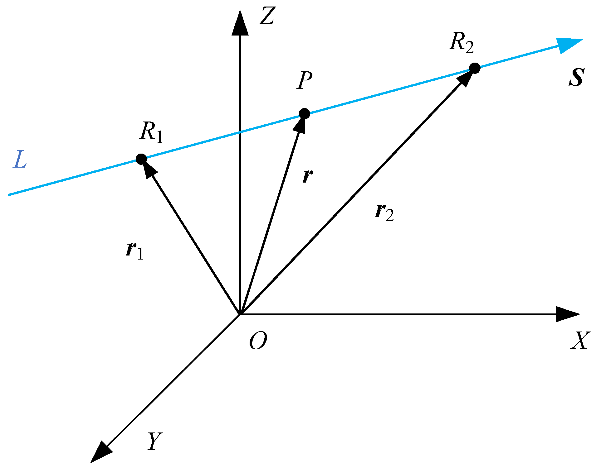
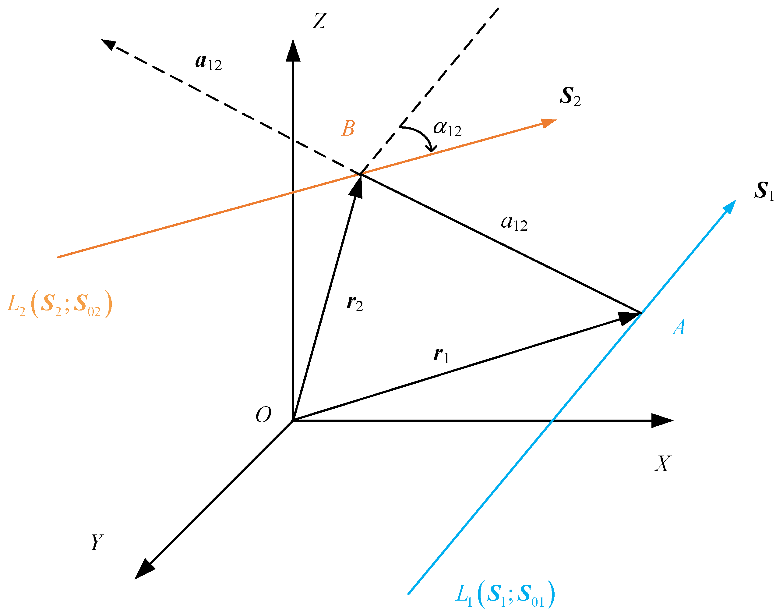
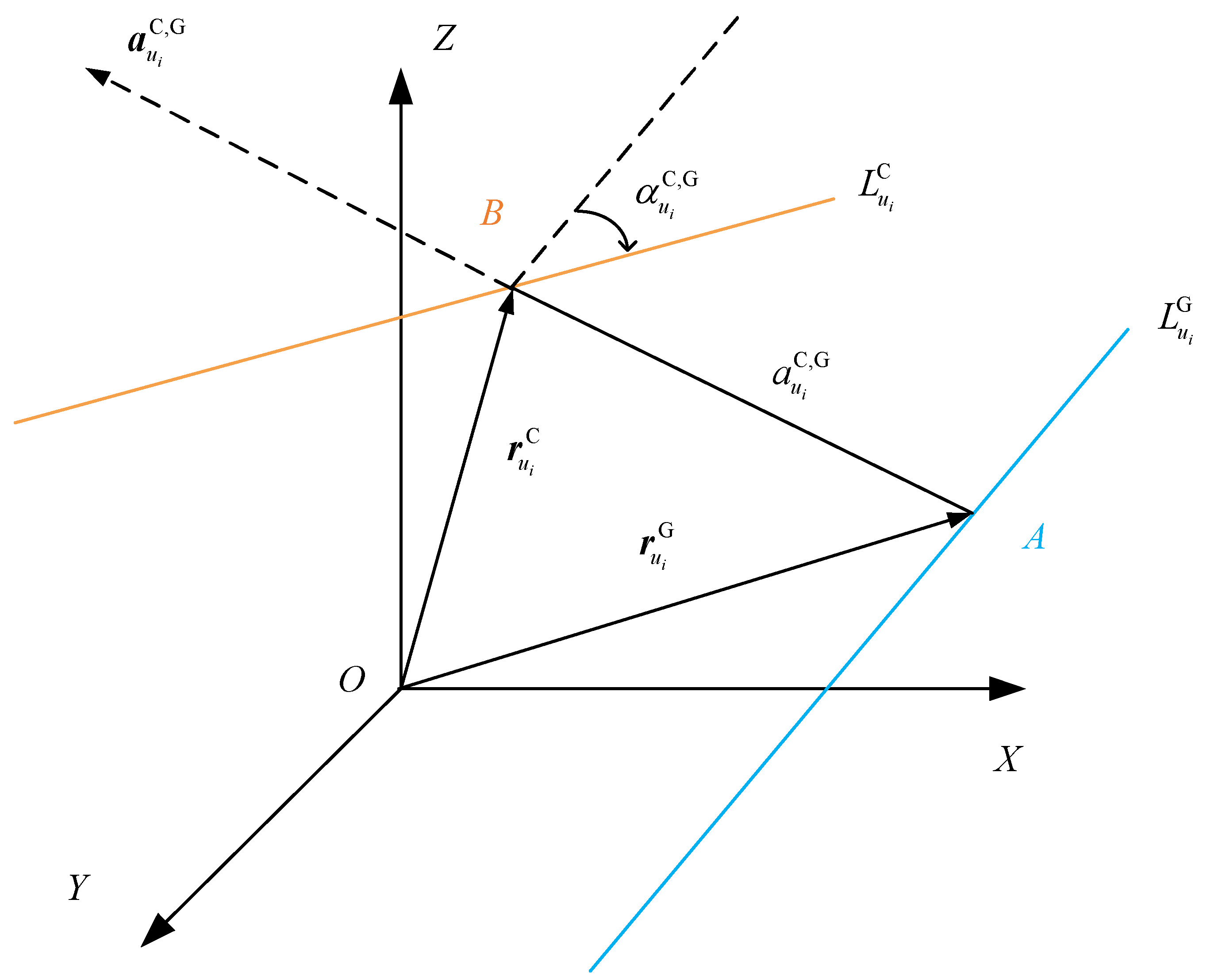
2.2. The Description of Mutual Moment
- (1)
- The mutual moment is only related to the distance and the twist angle and is independent of the choice of origin O. In other words, the mutual moment is independent of the choice of the coordinate system.
- (2)
- If two lines are parallel to each other, or if two lines cross at infinity, which means that at these two conditions, then mutual moment of the two lines is equal to zero. If two straight lines cross each other, which means that at this condition, then the mutual moment of the two lines is equal to zero. Therefore, if two spatial lines are coplanar, then the mutual moment of the two lines is equal to zero.
- (3)
- If the two direction vectors are not unit vectors, or , where and are unit vectors of the lines, in accordance with the principles of the vector cross product algorithm, the mutual moment can be expressed as .
- (4)
- The smaller the absolute value of the mutual moment, the greater the degree of coplanarity between the two straight lines.
2.3. The Presentation of Error Mutual Moment
- (1)
- The value of the mutual moment of error is independent of the selected coordinatization system. In the measuring process, the selection of the measuring coordinate system is often based on the geometric relationship between the forming surfaces of the workpiece. In the manufacturing process, the selection of the machining coordinate system is often based on the shape characteristics of the blank, and the selection of the workpiece coordinate system is often based on the structural function of the workpiece. Therefore, the determinations of zero point of each coordinate system are not aligned. In the calculation of the error mutual moment, it is not necessary to convert the coordinates of the measuring points of the component obtained in the measuring coordinate system to those of the workpiece coordinate system.
- (2)
- The smaller the value of the error mutual moment, the higher the degree of coplanarity between the two lines in this section. From Equation (9), the value of error mutual moment is determined by and ; thus, the error mutual moment is a consequence of the interaction between two factors: the perpendicular distance and the twist angle of the two lines. Comprehensively, the smaller the value of the error mutual moment, the higher the degree of coplanarity between the two lines.
- (3)
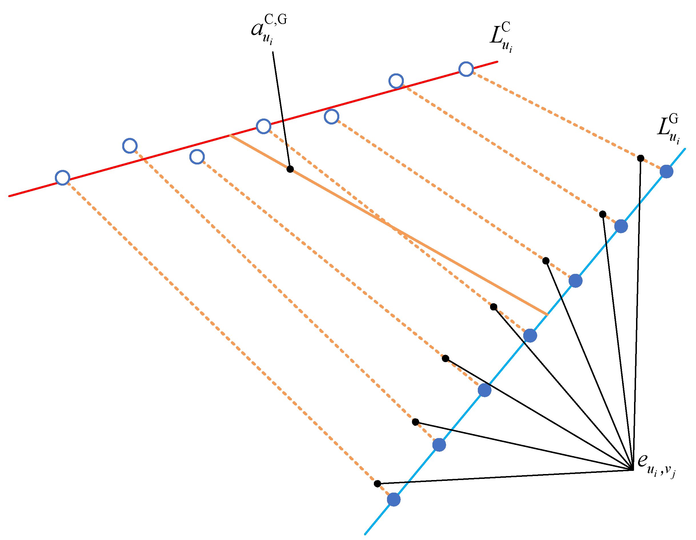
- Similar to the deviation, the mutual moment of error is determined by several factors during the machining. The qualitative expression for the error mutual moment can be expressed as:where f is the qualitative expression for the error mutual moment, C is the matrix of cutting parameters during machining, including but not limited to cutter parameters, the cutter eccentricity, or the error of the fixture. M is the matrix of the machine tool evolving machining, including but not limited to the topological structure, choice of the interpolation algorithm, or dynamic stiffness of each axis of the machine tool. In existing evaluations of the geometric quality of surfaces, the deviation between two points is similar to the perpendicular distance between the perpendiculars of two straight lines since it refers to the degree of deviation of the actual points (lines) from the theoretical points (lines), i.e., the two indicators are of the same order of magnitude. It can thus be surmised that the deviation between the two points is affected by the same factors as the perpendicular distance between the two straight common perpendiculars. In other words, the deviation is related to the real-time machining parameters and the choice of machine tool. In this paper, is defined as the twist angle between the actual contact line and the theoretical contact line; thus, is related to dynamic lag of the tool orientation during machining, and it must be related to the choice of machine tool.
- (4)
- The utilization of error mutual moment provides a more comprehensive information of the CNC machine’s capability for dynamic machining performance. Especially, the error mutual moment has more advantages on assessing the capability for dynamic machining performance compared with the deviation. Figure 6 describes the relationship between error mutual moment and deviation. and denote the fitted actual and theoretical contact line, respectively. The blue hollow points are theoretical points, and the blue solid points are actual measurement points. The orange solid line is the perpendicular distance between the two lines, and the orange dotted lines are the deviations between two corresponding points. Based on the law of spatial geometric relationship, it is known as:The equality sign is satisfied if and only if the two lines are coplanar; and even if this situation occurs, , . Accordingly, the value of the error mutual moment provides information regarding both the distance information and angular information between the actual and theoretical contact lines in this section.
3. Experiment
3.1. Setup of the Experiment
3.2. Results of the Experiment
3.3. Discussion
4. Conclusions and Future Outlook
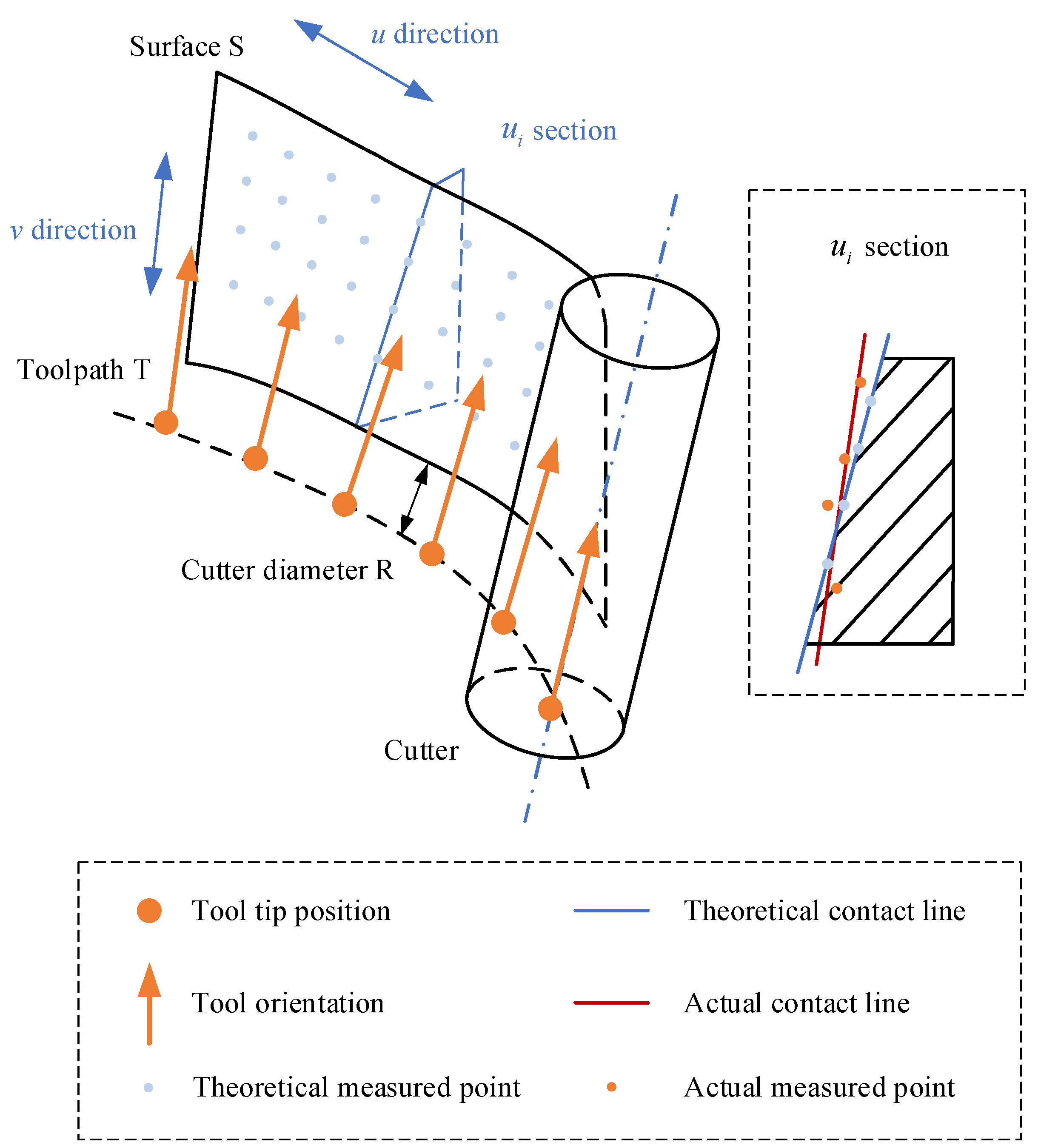
- The characteristic of the error distribution of the flank milling is analyzed and the non-coplanarity between the theoretical and actual contact lines is selected as the basic indicator.
- A rigorous mathematical derivation is demonstrated for the indicator based on the spatial coordinate information by calculating the degree of non-coplanarity between the theoretical and actual contact lines. The error mutual moment and its model are given.
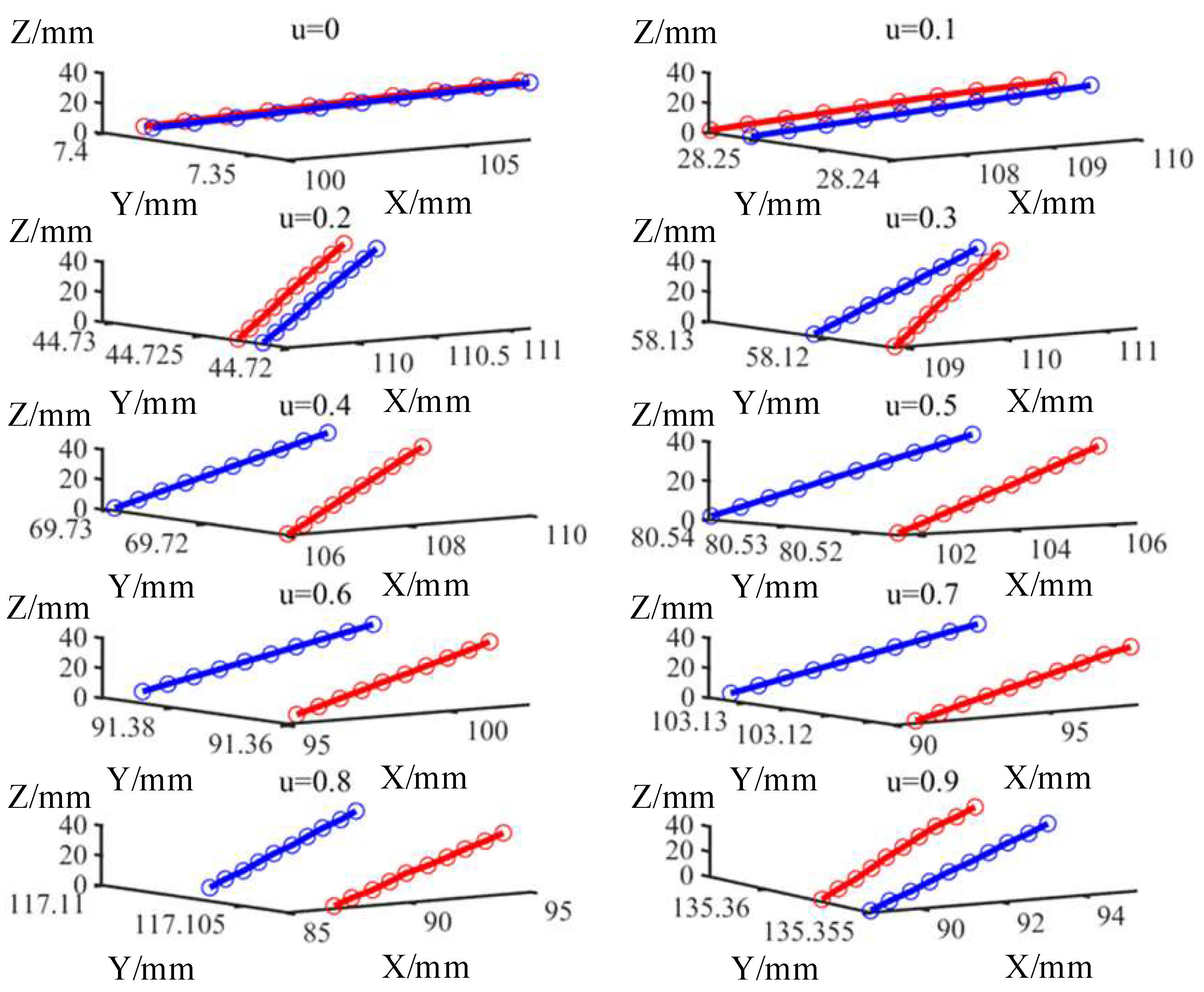
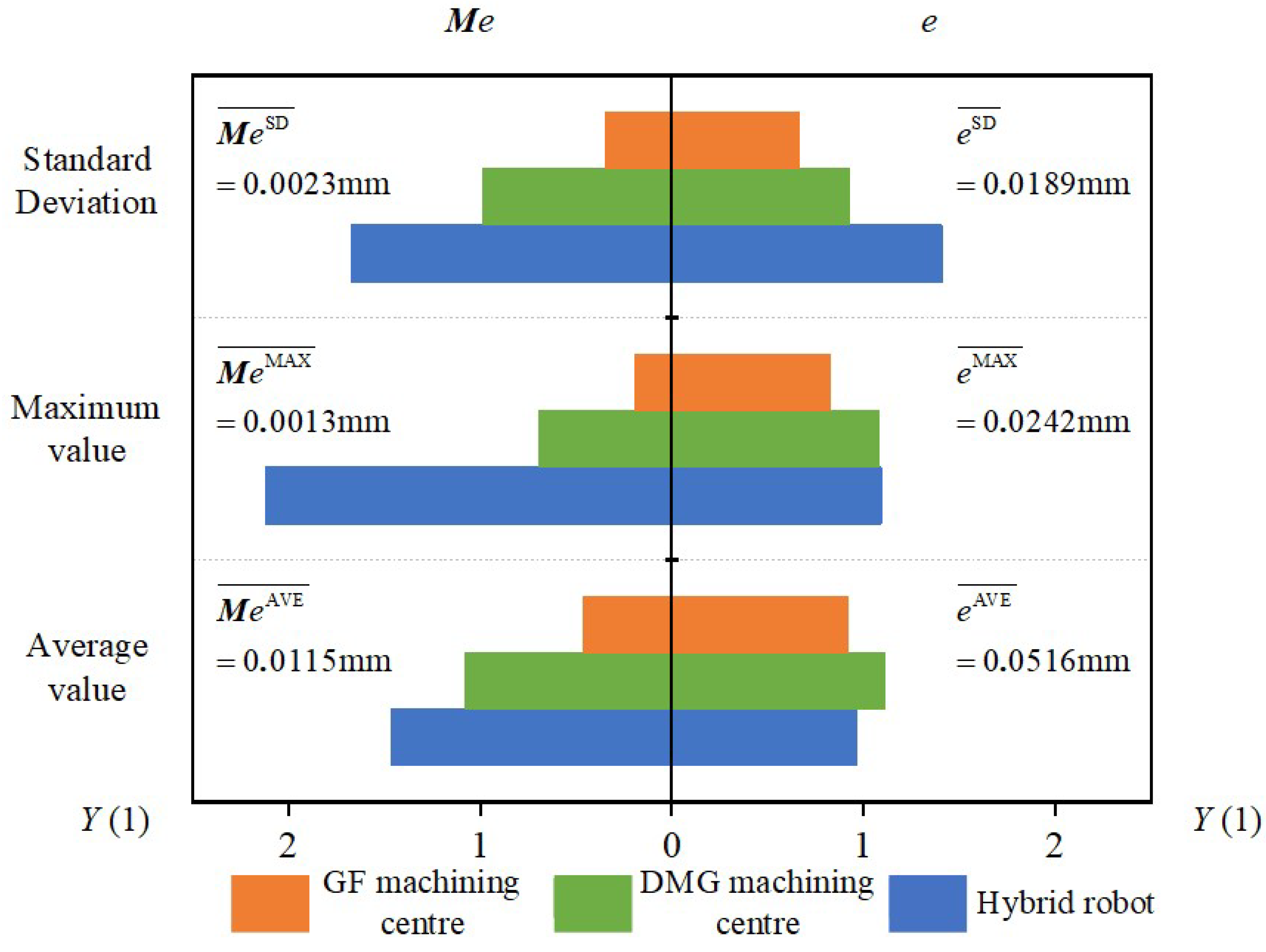
- A comparative experiment of the error mutual moment and the deviation is designed, which aims to assess the capability for dynamic machining performance across the machine tools.
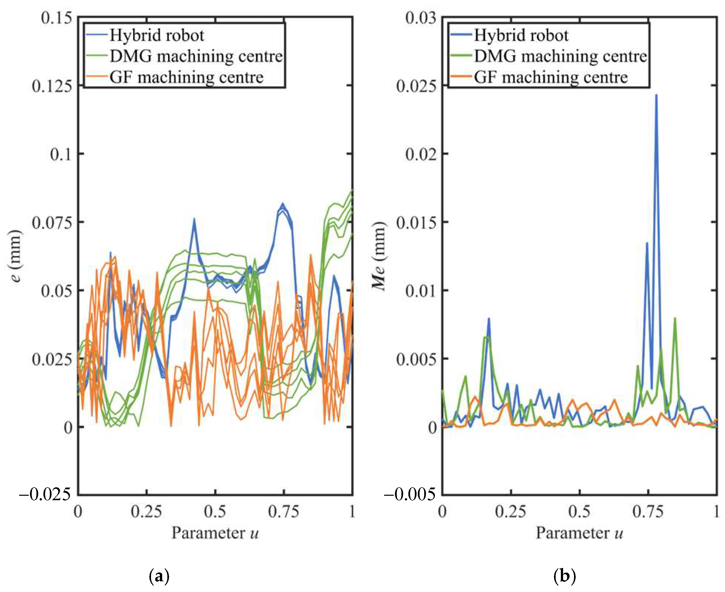
- The results of the experiment proved that the error mutual moment showed more significant difference than the deviation to assess the capability for dynamic machining performance across the machine tools.
Author Contributions
Funding
Institutional Review Board Statement
Informed Consent Statement
Data Availability Statement
Conflicts of Interest
References
- Yu, D.; Ding, Z.; Tian, X. High-precision machining technology based on analytical method for integral impeller with flank milling. Int. J. Adv. Manuf. Tech. 2021, 114, 2309–2319. [Google Scholar] [CrossRef]
- Zhang, J.; Mo, R.; Wan, N.; Xia, C. Tool path planning for five-axis flank milling of free-form surfaces. Int. J. Adv. Manuf. Tech. 2020, 108, 73–90. [Google Scholar] [CrossRef]
- González, H.; Pereira, O.; López de Lacalle, L.N.; Calleja, A.; Ayesta, I.; Muñoa, J. Flank-milling of integral blade rotors made in Ti6Al4V using cryo CO2 and minimum quantity lubrication. J. Manuf. Sci. Eng. 2021, 143, 091011. [Google Scholar] [CrossRef]
- Urbikain, G.; de Lacalle, L.L. Modelling of surface roughness in inclined milling operations with circle-segment end mills. Simul. Model. Pract. Theory 2018, 84, 161–176. [Google Scholar] [CrossRef]
- Li, D.; Wang, B.; Tong, Z.; Blunt, L.; Jiang, X. On-machine surface measurement and applications for ultra-precision machining: A state-of-the-art review. Int. J. Adv. Manuf. Technol. 2019, 104, 831–847. [Google Scholar] [CrossRef]
- Mutilba, U.; Gomez-Acedo, E.; Kortaberria, G.; Olarra, A.; Yagüe-Fabra, J.A. Traceability of on-machine tool measurement: A review. Sensors 2017, 17, 1605. [Google Scholar] [CrossRef]
- Wan, N.; Jiang, R.; Zhao, H.; Zhang, S. An inspection path optimization of impeller for balancing efficiency and accuracy. Measurement 2019, 141, 472–485. [Google Scholar] [CrossRef]
- Tan, G.; Zhang, L.; Liu, S.; Zhang, W. A fast and differentiated localization method for complex surfaces inspection. Int. J. Precis. Eng. Manuf. 2015, 16, 2631–2639. [Google Scholar] [CrossRef]
- Mutilba, U.; Sandá, A.; Vega, I.; Gomez-Acedo, E.; Bengoetxea, I.; Fabra, J.A.Y. Traceability of on-machine tool measurement: Uncertainty budget assessment on shop floor conditions. Measurement 2019, 135, 180–188. [Google Scholar] [CrossRef]
- Zhao, B.; Gao, F.; Li, Y.; Fan, L. Study on pre-travel anisotropic characteristic of touch trigger probe and its calibration method. In Proceedings of the 2015 12th IEEE International Conference on Electronic Measurement & Instruments (ICEMI), Qingdao, China, 16–18 July 2015; Volume 2, pp. 1024–1028. [Google Scholar]
- Jankowski, M.; Wonzniak, A. Mechanical model of errors of probes for numerical controlled machine tools. Measurement 2016, 77, 317–326. [Google Scholar] [CrossRef]
- Cai, Y.; Cui, N.; Mo, X.; Yao, X.; Sun, W. The Pre-travel error study of electrical trigger probe in on-machine measurement. Key Eng. Mater. 2016, 693, 1466–1473. [Google Scholar] [CrossRef]
- Ahn, H.K.; Kang, H.; Ghim, Y.S.; Yang, H.S. Touch probe tip compensation using a novel transformation algorithm for coordinate measurements of curved surfaces. Int. J. Precis. Eng. Manuf. 2019, 20, 193–199. [Google Scholar] [CrossRef]
- Li, S.; Zeng, L.; Feng, P.; Li, Y.; Xu, C.; Ma, Y. Accurate compensation method for probe pre-travel errors in on-machine inspections. Int. J. Adv. Manuf. Technol. 2019, 103, 2401–2410. [Google Scholar] [CrossRef]
- Rajamohan, G.; Shunmugam, M.S.; Samuel, G.L. Effect of probe size and measurement strategies on assessment of freeform profile deviations using coordinate measuring machine. Measurement 2011, 45, 832–841. [Google Scholar] [CrossRef]
- He, G.; Sang, Y.; Pang, K.; Sun, G. An improved adaptive sampling strategy for freeform surface inspection on CMM. Int. J. Adv. Manuf. Technol. 2018, 96, 1521–1535. [Google Scholar] [CrossRef]
- Chen, Y.; Gao, J.; Deng, H.; Zheng, D.; Chen, X.; Robert, K. Spatial statistical analysis and compensation of machining errors for complex surfaces. Precis. Eng. 2013, 37, 203–212. [Google Scholar]
- Chen, Y.; Tang, H.; Tang, Q.; Zhang, A.; Chen, D.; Li, K. Machining error decomposition and compensation of complicated surfaces by EMD method. Measurement 2018, 116, 341–349. [Google Scholar] [CrossRef]
- Chen, Y.; Xu, J.; Tang, Q. Decomposition of machining error for surfaces using complete ensemble empirical mode decomposition with adaptive noise. Int. J. Comput. Integr. Manuf. 2021, 34, 1049–1066. [Google Scholar] [CrossRef]
- Hsieh, H.; Chu, C. Improving optimization of tool path planning in 5-axis flank milling using advanced PSO algorithms. Robot. Comput. Integr. Manuf. 2013, 29, 3–11. [Google Scholar] [CrossRef]
- Liu, X. Five-axis NC cylindrical milling of sculptured. Comput. Aided Des. 1995, 27, 887–894. [Google Scholar] [CrossRef]
- Redonnet, J.; Rubio, W.; Dessein, G. Side milling of ruled surfaces: Optimum positioning of the milling cutter and calculation of interference. Int. J. Adv. Manuf. Technol. 1998, 14, 459–465. [Google Scholar] [CrossRef]
- Sanjeev, B.; Stephen, M.; Cornelia, M. Flank milling with flat end milling cutters. Comput. Aided Des. 2003, 35, 293–300. [Google Scholar]
- Menzel, C.; Bedi, S.; Mann, S. Triple tangent flank milling of ruled surfaces. Comput. Aided Des. 2004, 36, 289–296. [Google Scholar] [CrossRef]
- Guan, L.; Mo, J.; Fu, M.; Wang, L. An improved positioning method for flank milling of S-shaped test piece. Int. J. Adv. Manuf. Technol. 2017, 92, 1349–1364. [Google Scholar] [CrossRef]
- Sun, S.; Yan, S.; Jiang, S.; Sun, Y. A high-accuracy tool path generation (hatpg) method for 5-axis flank milling of ruled surfaces with a conical cutter based on instantaneous envelope surface modelling. Comput. Aided Des. 2022, 151, 103354. [Google Scholar] [CrossRef]
- Lartigue, C.; Duc, E.; Affouard, A. Tool path deformation in 5-axis flank milling using envelope surface. Comput. Aided Des. 2003, 35, 375–382. [Google Scholar] [CrossRef]
- Ding, H.; Zhu, L. Global optimization of tool path for five-axis flank milling with a cylindrical cutter. Sci. China Ser. E 2009, 52, 2449–2459. [Google Scholar] [CrossRef]
- ANSI Y14.5; Dimensioning and Tolerancing. The American Society of Engineers: New York, NY, USA, 1982.
- ISO/R 1101; Technical Drawings-Geometrical Tolearncing. International Organization for Standardization: Geneva, Switzerland, 1983.
- Yao, C.; He, G.; Ma, W.; Yan, Y.; Wang, S.; Yue, C. A finishing toolpath generation strategy for flank milling of ruled surface based on a Double-Point-Mirror method. Int. J. Adv. Manuf. Technol. 2023, 129, 3185–3195. [Google Scholar] [CrossRef]
- Mou, W.; Song, Z.; Guo, Z.; Tang, L. A machining test to reflect dynamic machining accuracy of five-axis machine tools. Adv. Mat. Res. 2012, 622-623, 414–419. [Google Scholar] [CrossRef]
- NAS 979; Uniform Cutting Tests—Metal Cutting Equipment Specifications. Aerospace Industries Association of America: Arlington, VA, USA, 1969.
- Jiang, Z.; Ding, J.; Song, Z.; Du, L.; Wang, W. Modeling and simulation of surface morphology abnormality of ‘S’ test piece machined by five-axis CNC machine tool. Int. J. Adv. Manuf. Technol. 2015, 85, 2745–2759. [Google Scholar] [CrossRef]
- Wang, W.; Jiang, Z.; Li, Q.; Tao, W. A new test part to identify performance of five-axis machine tool-Part II validation of S part. Int. J. Adv. Manuf. Technol. 2015, 79, 739–756. [Google Scholar] [CrossRef]
- Wang, W.; Jiang, Z.; Tao, W.; Zhuang, W. A new test part to identify performance of five-axis machine tool—Part I: Geometrical and kinematic characteristics of S part. Int. J. Adv. Manuf. Technol. 2015, 79, 729–738. [Google Scholar] [CrossRef]
- Xie, D.; Ding, J.; Liu, F.; Jiang, Z.; Du, L.; Wang, W.; Song, Z. Modeling errors forming abnormal tool marks on a twisted ruled surface in flank milling of the five-axis CNC. J. Mech. Sci. Technol. 2015, 28, 4717–4726. [Google Scholar] [CrossRef]
- ISO10791-7(2020); Test Conditions for Machining Centres. Part 7: Accuracy of Finished Test Pieces. International Organization for Standardization: Geneva, Switzerland, 2020.
- Ihara, Y.; Takubo, K.; Nakai, T.; Sato, R. Effect of CAD/CAM post process on S-shaped machining test for five-axis machining center. Int. J. Auto Tech-Jpn. 2019, 13, 593–601. [Google Scholar] [CrossRef]
- Ihara, Y.; Kajino, S.; Inoue, Y. Feasibility of 8-shaped motion test for five-axis machining center. Int. J. Auto. Tech. Jpn. 2023, 17, 477–485. [Google Scholar] [CrossRef]
- Xiao, J.; Liu, S.; Liu, H.; Wang, M.; Li, G.; Wang, Y. A jerk-limited heuristic feedrate scheduling method based on particle swarm optimization for a 5-DOF hybrid robot. Robot. Comput. Integr. Manuf. 2022, 78, 102396. [Google Scholar] [CrossRef]
- Sang, Y. Study on the Comprehensive Evaluation Method of the Geometrical Quality of S-Shaped Test Piece. Ph.D. Thesis, Tianjin Univercity, Tianjin, China, 2021. [Google Scholar]

| Parameters | Values |
|---|---|
| Numerical control system | HEIDENHAIN TNC530 |
| Ranges of the X/Y/Z axis (mm) | 630/560/560 |
| Turning range of B axis | −120°~30° |
| Rotation range of C axis | 0°~360° |
| Maximum feedrate (m/min) | 30 |
| Parameters | Values |
|---|---|
| Numerical control system | HEIDENHAIN TNC640 si |
| Ranges of the X/Y/Z axis (mm) | 500/600/450 |
| Turning range of B axis | −120°~90° |
| Rotation range of C axis | 0°~360° |
| Maximum feedrate (m/min) | 45 |
| Parameters | Values |
|---|---|
| Numerical control system | Self-made numerical control system |
| Workspace (mm) | Φ1600 × 400 |
| Maximum feedrate (m/min) | 90 |
 | Cutting Parameters | Values |
| Material of the part | Aluminum alloy 7075 | |
| Tool type | End mill | |
| Tool diameter | 20 mm | |
| Spindle speed | 6000 rpm | |
| Feedrate in finishing | 1500 mm/min | |
| Radial depth of cut in finishing | 0.05 mm | |
| Number of axial cutting layers | 1 |
| DMG Machine Centre | GF Machine Centre | Hybrid Robot | ||
|---|---|---|---|---|
| Deviation (mm) | Maximum value | 0.0607 | 0.0464 | 0.0614 |
| Average value | 0.0269 | 0.0222 | 0.0234 | |
| Standard deviation | 0.0175 | 0.0126 | 0.0267 | |
| Error mutual moment (mm) | Maximum value | 0.0079 | 0.0022 | 0.0243 |
| Average value | 0.0014 | 0.0006 | 0.0019 | |
| Standard deviation | 0.0023 | 0.0008 | 0.0039 |
Disclaimer/Publisher’s Note: The statements, opinions and data contained in all publications are solely those of the individual author(s) and contributor(s) and not of MDPI and/or the editor(s). MDPI and/or the editor(s) disclaim responsibility for any injury to people or property resulting from any ideas, methods, instructions or products referred to in the content. |
© 2024 by the authors. Licensee MDPI, Basel, Switzerland. This article is an open access article distributed under the terms and conditions of the Creative Commons Attribution (CC BY) license (https://creativecommons.org/licenses/by/4.0/).
Share and Cite
Yao, C.; He, G.; Sang, Y.; Yue, C.; Yan, Y.; Wang, S. An Indicator Based on Spatial Coordinate Information for Assessing the Capability for Dynamic Machining Performance of Five-Axis Flank Milling. Sensors 2024, 24, 7229. https://doi.org/10.3390/s24227229
Yao C, He G, Sang Y, Yue C, Yan Y, Wang S. An Indicator Based on Spatial Coordinate Information for Assessing the Capability for Dynamic Machining Performance of Five-Axis Flank Milling. Sensors. 2024; 24(22):7229. https://doi.org/10.3390/s24227229
Chicago/Turabian StyleYao, Chenglin, Gaiyun He, Yicun Sang, Chen Yue, Yichen Yan, and Sitong Wang. 2024. "An Indicator Based on Spatial Coordinate Information for Assessing the Capability for Dynamic Machining Performance of Five-Axis Flank Milling" Sensors 24, no. 22: 7229. https://doi.org/10.3390/s24227229
APA StyleYao, C., He, G., Sang, Y., Yue, C., Yan, Y., & Wang, S. (2024). An Indicator Based on Spatial Coordinate Information for Assessing the Capability for Dynamic Machining Performance of Five-Axis Flank Milling. Sensors, 24(22), 7229. https://doi.org/10.3390/s24227229


