Abstract
Achieving the simultaneity of ventilation and soundproofing is a significant challenge in applied acoustics. Ventilated soundproofing relies on the interplay between local resonance and nonlocal coupling of acoustic waves within a sub-wavelength structure. However, previously studied structures possess limited types of fundamental resonators and lack modifications from the basic arrangement. These constraints often force the specified position of each attenuation peak and low absorption performance. Here, we suggest the in-duct-type sound barrier with dual Helmholtz resonators, which are positioned around the symmetry-breaking waveguides. The numerical simulations for curated dimensions and scattered fields show the aperiodic migrations and effective amplifications of the two absorptive domains. Collaborating with the subsequent reflective domains, the designed structure holds two effective attenuation bands under the first Fabry–Pérot resonance frequency. This study would serve as a valuable example for understanding the local and non-local behaviors of sub-wavelength resonating structures. Additionally, it could be applied in selective noise absorption and reflection more flexibly.
1. Introduction
Acoustic noise is an undesirable result of all living and industrial activities. Parallel to the increasing number of population and diversity of devices, the property of interested noise constantly changes [1,2]. In contrast, the conventional noise reduction method during the transmission stage remains static: blocking the path or space near the noise sources with sound absorbing materials (SAMs) [3,4]. SAMs generally adhere to the mass-density law, resulting in linear absorption performance for the low-frequency range [5]. Lower interactions between long-wavelength waves and structure lead to less energy dissipations; thicker and heavier SAMs are required for sufficient noise reduction. Thus, achieving simultaneity in addressing low-frequency noise and ventilation requirements poses a significant challenge.
Acoustic metamaterials (AMMs) are artificial structures composed of purposely arranged resonators in a sub-wavelength scale. With the resolution criterion by wave property, AMMs are equated with the effective medium of the same volume that owns effective mass density ρ and effective bulk modulus κ [6,7]. Unlike previous chemically categorized ordinary materials, the strong dispersion of resonating components results in a complex range of effective properties: positive, negative, and near-zero values [8,9,10,11,12]. These unprecedented properties open up new possibilities for promising research topics such as acoustic focusing [13,14,15], acoustic clocking [16,17,18], acoustic communications [19,20,21], and acoustic absorbers [22,23].
Over the past decade, ventilated soundproofing with AMMs has been conceptualized and developed as duct noise approaches [24,25,26,27]. For an in-duct structure, the transverse bilayer concept has been widely implemented, featuring a central passage and surrounding space-coiled half-wavelength resonators [28,29,30]. Continuum state waves from the former and discrete state waves from the locally resonating latter result in destructive interferences, known as Fano-like interference, occurring at periodic frequency points. Reflective domains are broadened between the points by the non-local coupling of waves [31,32]. While this structural type offers great advantages in terms of simple design and broadband transmission loss, its reduction is periodically restrained and dependent on reflection.
Another common approach involves a symmetric central passage surrounded by end-closed locally resonating structures such as space-coiled quarter-wavelength resonators (QWRs) [33,34,35] and Helmholtz resonators (HRs) [36,37]. Under the first Fabry–Pérot resonance point, the mutual response of the contracted central passage and each resonator yields partial reflective and absorptive domains [38]. However, much of previous research tended to suggest attenuation performance without a clear classification of them. Only the less of them discussed the effective control of the absorptive domain [35]. Therefore, achieving noise control with efficient absorption performance requires ongoing trials and discussions on various fundamental local resonators and arrangement-induced non-local interactions.
Here, we conceptually present an in-duct type hollow acoustic structure with dual Helmholtz resonators (DHRs) and asymmetric waveguides for wave manipulation. These properties lead to over 90% attenuation of incident sound energy across the two frequency ranges; one is from 550 Hz to 874 Hz and the other is from 1344 Hz to 2500 Hz, owning the absorptive domains from 542 Hz to 707 Hz and 1344 Hz to 1688 Hz. Notably, these two absorption bands are influenced by the accumulated and reinforced two aperiodic resonance peaks of each DHR within asymmetric arrangements. Thus, this study may be instructive in finding the relation between the fundamental resonator and its arrangement in sub-wavelength resonating structures. Additionally, it would mark the beginning of utilizing absorptive domains for reducing non-regular peak noise in various application scenarios.
2. Design and Simulation for Acoustic Metastructure
Noise and flow undergo soundproofing and ventilation as they traverse the designed structure in Figure 1a. The ventilation of the background medium stems from the central orifice. Effective attenuation occurs through the acoustical response of the orifice and the surrounding resonators. The orifice behaves as a Fabry–Pérot resonator, which transmits all the energy when it periodically resonates. Between the passing points, it reflects the most incident energy due to the mismatched impedance. This transmissive and reflective property results in an insufficient absorption coefficient. The effective absorption response would derive from the surrounding resonators. It induces additional resonance under the first Fabry–Pérot resonance, where an asymmetric reflection takes place. This profile, called Fano-like interference, escorts the effective absorption coefficient at the dip of reflection response. The magnitude of the absorption coefficient would vary depending on the design of the resonator in each case [35,36].
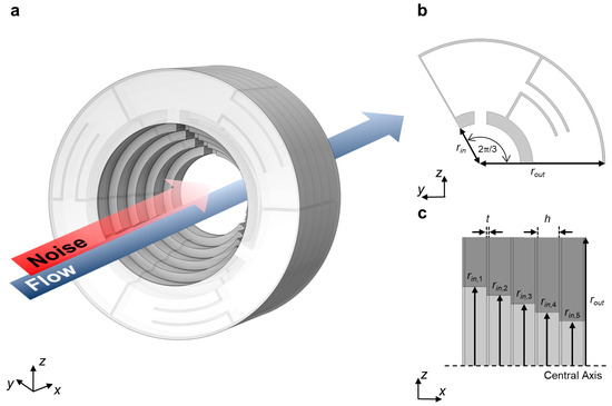
Figure 1.
Schematics of designed metastructure with certain parameters. (a) Conceptual view of the designed metastructure. (b) Radial plane (yz plane) view of the layer, focusing on the unit DHR. Outer radius rout = 50 mm and inner radius rin, which varies through the layer. (c) Axial plane (zx plane) view of the designed metastructure. The thickness of the general wall t = 1 mm and the height of unit DHR h = 8.8 mm.
To manage the absorption performance, we introduce the DHR as a fundamental resonator. One single Helmholtz resonator (SHR) is connected to the central passage with radius rin, while the other is radially connected to the cavity of the previous one. This configuration molds the DHR of the outer radius rout, as depicted in Figure 1b. The DHR defines its two resonance frequencies based on its dimension parameters [39]. It leads to a great degree of freedom in setting the resonance frequencies, compared to the restrained peak position of the QWR only by its length. When the DHR responds to these frequencies, massive dissipation would take place in each neck region. This characteristic indicates that DHR enables the thorough control of absorption peaks by precisely selected dimensions.
The designed structure comprises a stack of five layers, whose inner radii are narrow over the +x direction, as depicted in Figure 1c. Each layer accommodates the three DHRs in a radial sequence. With these configurations, we promote an increase in the absorption coefficient due to two aspects. One is the asymmetric shape that defines the scattering coefficient dissimilarly based on the incident propagate direction. This definition divides the reflection coefficient by the incident direction, which contributes to controlling the absorption coefficient in a more unconstrained way. The other is critical damping in a DHR or a specific layer. This concept happens when the following layer functions as an effective rigid wall, which reflects the incident energy. This backward energy would be efficiently dissipated if the front layer could resonate with the reflected wave [40].
The designed resonator and metastructure are numerically simulated by using the pressure acoustic module in COMSOL MultiphysicsTM 6.1. To estimate the noise attenuation performance, we conduct the frequency domain study. Scattering coefficients are gained through the plane wave ports, which are located at both ends of the cylindrical waveguides. A large impedance difference between air and structural material leads every wall to be acoustically rigid. We account for the intrinsic losses from viscous and thermal dissipation, which mainly occurs at neck sections. Those domains are assigned to the narrow-region acoustic. With this simulation set-up, only the material property of air was employed as follows: density ρair = 1.29 kg/m3, speed of sound cair = 331 m/s, Prandtl number Pr = 0.71, ratio of specific heats γ = 1.4, dynamic viscosity η = 1.839 × 10⁻⁵ kg m−1 s−1 and atmosphere pressure Patm = 101,325 Pa.
The numerical simulation in Section 3.1 focuses on studying the side-branched unit DHR with open region radius rin = 16 mm. In Section 3.2, two types of models were simulated. One aims to investigate the band diagram of the designed structure. Only the air domain, which fills the inside of the structure, was modeled. Periodic boundary condition was selected on the inlet and outlet, which simplifies the interested wave vector into only the x direction. The other type of model is for calculating scattering responses for in-duct structure. It includes the cylindrical waveguide, which is extruding in both directions from structures along the x direction (see details in the Supplementary Materials).
3. Results and Discussion
3.1. Dual Helmholtz Resonators
Large-scale differences in wavelength and structure dimension allow for the simplification of wave analysis as a harmonic oscillator [41]. Especially for the resonating structure, it approximates the forced damped system with equivalent excitation strength, mass element, and spring element [42]. These properties lead the DHR to the mass-spring–mass-spring model, as illustrated in Figure 2a. This equivalency results in the finding that the resonance frequency of DHR corresponds to the natural frequency of the oscillating model. The connected mass in each neck of ith SHR mi would satisfy Equations (1) and (2) by Newton’s second law and the following variables: angular frequency ω, the density of air ρair, speed of sound cair, oscillating displacement of neck mass in each SHR xi, the cross-sectional area of the neck in ith SHR Ani, and effective resonating volume of ith SHR Vi [39].
The effective length of the neck in ith SHR l’ni was introduced, which replaces the notation mass as (see details in the Supplementary Materials). This replacement binds Equations (1) and (2), which results in the matrix form. It represents Hooke’s law with the sequence of kx = F. The eigenvalue of the given stiffness matrix would correspond to the resonance frequency of the DHR, as shown in Equation (4).
The dissipation, which comes from massive energy exchange to the external, would occur at the resonance state. It implies that the absorption peaks are located near the analytically defined resonance frequency in Equation (4). Numerical simulations were conducted for each SHR and unit DHR with assigned dimension values for the validation. All resonators were connected in a side-branched way to solely measure the absorption coefficient. Figure 2b represents its result, which adheres to the theory of point-symmetric scatter. This theory imposes a limitation on the maximum value of the absorption coefficient to 1/2 [43]. In the comparison of analytical resonance frequency (red dot) and numerical absorption peak frequency (black line), they are located close together with some deviation. The common deviation might stem from the value of the end-corrected length. A relatively large deviation on f2 comes from the unique resonance of SHR 1. As the shorter neck length of SHR 1, it has a larger resonance frequency than SHR 2. When those SHRs connect and SHR 1 resonates, not only the neck and cavity of SHR 1, but the part of SHR 2 neck also resonates as an effective volume. It results in the approximation of resonating volume, which manifests the deviation.
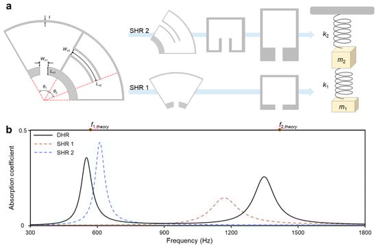
Figure 2.
Design and absorption coefficient of unit DHR. (a) Approximation of designed unit DHR into connected two pairs of a mass-spring system. One pair is from SHR 1 with the following parameters: central angle of cavity θ1 = 60°, neck width Wn1 = 5 mm, and neck length Ln1 = 5 mm. The other is from SHR 2 with the following parameters: central angle of the cavity 120°—θ1, neck width Wn2 = 4 mm, central angle of the embedded neck θ2 = 40°, and corresponding neck length Ln2 = ((rin + Ln1 + rout − t)/2) × θ2 × (π/180) = 24.43 mm. (b) Absorption coefficient of unit DHR, SHR 1, and SHR 2. Two red dots represent the analytical resonance frequency of DHR.
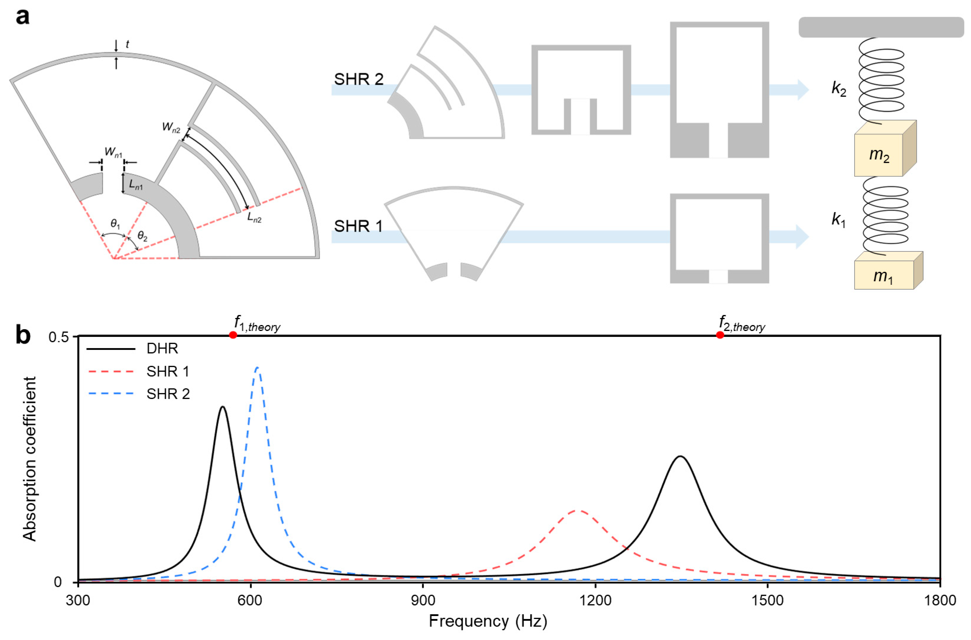
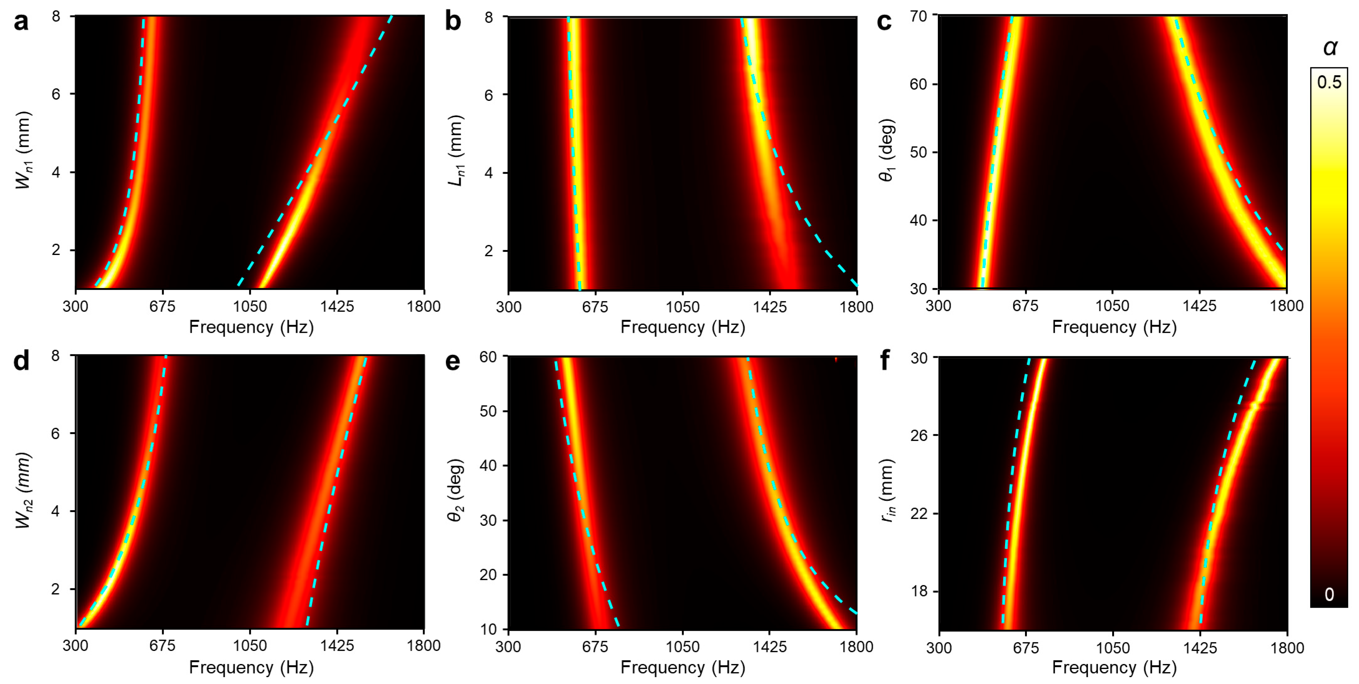
The transition and amplification of absorption peaks are confirmed through the geometrical studies shown in Figure 3. The cyan dashed line in Figure 3 represents the resonance frequency of unit DHR through the parametric study for each dimension. All trends align closely with the absorption peaks of the numerical calculations. It implies that the designed unit DHR maintains the property of the connected two Helmholtz resonators even with the geometric changes. This consistent analysis underscores the notion that the selection of parameters determines the response of the lossy mechanical system in each scenario. Parameters are categorized based on their impact on the structure following this discussion.
Figure 3.
The absorption coefficient (α) by the varying geometric parameters. The dashed line for the analytical resonance frequency. (a,b) Parameters related to the neck of SHR 1: width Wn1 and length Ln1, respectively. (c) Circular sector angle of the first cavity θ1. (d,e) Parameters related to the neck of SHR 2: width Wn2 and length factor θ2, respectively. (f) Open region radius rin.
Dimensions, which are related to each neck part, induce not only frequency shifts but also absorption amplification. A narrower neck width shifts both peaks to a lower frequency by following Equation (4). The second peak of the absorption coefficient shows a causal tendency with changes in Wn1, leading to larger losses by resonating in the smaller space. This relation is also valid between Wn2 and the first peak of the absorption coefficient. Longer neck length exhibits a comparable effect to the narrower neck width. The dimensions of the cavity would mainly induce the shifts in peak frequency on the same principle. θ1 and rin are the variables that only change the volume of each cavity. They mainly exhibit the variation in resonance frequency, not in the amplitude of the absorption coefficient. Change in θ1 leads to the volume fraction between two cavities in limited space: θ1 and θ2 = 120° − θ1. This results in non-parallel shifting of resonance points, which could be either converged or dispersed. Alternations in rin bring parallel shifting, allowing for the changes in each cavity volume in the same way. These findings suggest that DHR could offer flexibility in dimension selection when a certain property of absorption coefficient is required.
3.2. Resonators in Asymmetric Waveguides
Metastructures often use multilayered fundamental resonators to enhance both the magnitude and bandwidth of the target property [27,38]. These improvements stem from the non-local properties, which originate from the interactions among closely located resonators. We employ the concept of symmetry-breaking structures to enhance the absorption performance. The asymmetry configuration defines the scattering coefficient differently depending on the direction of the incident wave. This opens up the possibility of attaining zero values in two eigenvalues of the scattering matrix, which theoretically corresponds to perfect absorption [40]. An elevated absorption coefficient could be achieved with the resonators that simultaneously suppress both transmission and reflection. These suppressions are realized through the effective reflecting wall and critical coupling, respectively. Within the asymmetry configuration, the rear-located resonator acts as a reflecting wall just above its resonance frequency. The front-located resonator, which matches its impedance to the surroundings in that frequency, shows the critical coupling [44].
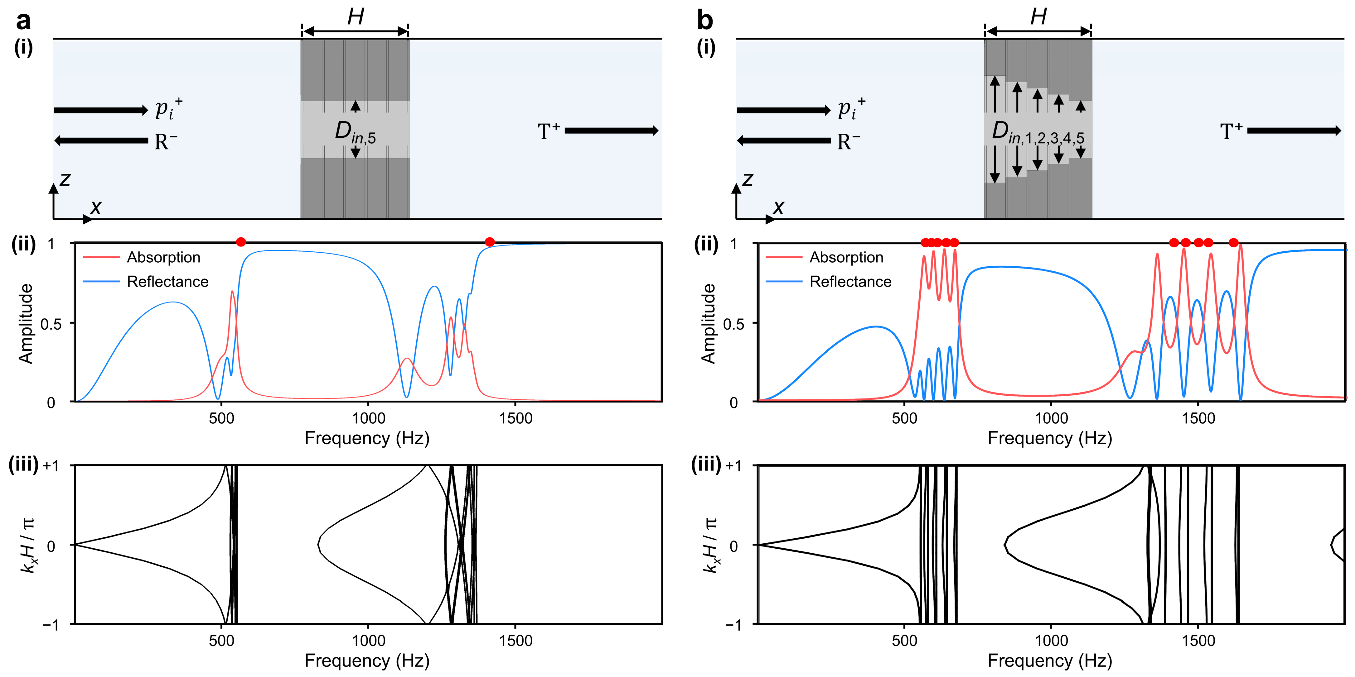
To implement the absorption amplification in asymmetrical structures, we conducted a comparative analysis between the two models. Each model consists of five layers, where three DHRs are accommodated in every layer. It generates two absorptive peaks in low and high frequencies. One model has a constant Din, while the other has varying Din, as depicted in Figure 4. These two models share the same dimensions for DHRs, except only for the value of Din. The inlet diameter of each layer Din,i is assigned as Table 1. Gradient modification in Din,i ensures not only the structural asymmetry, but also suggests the evenly spaced resonance frequency f1,2 by analytical predictions. The Din increment toward Din,1 layer gets smaller to ensure the properly spaced resonance. This diminishing trend reflects the varying change rate in cavity volume, which is relative to the initial dimension of it. Even a small deviation in larger Din results in a relatively large increment in the cavity volume.
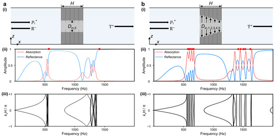
Figure 4.
The soundproofing performance of two different waveguide structures. (a) Symmetric central passage with constant inlet diameter. (b) Asymmetric central passage with decreasing inlet diameter along the +x direction. In each section, (i) depicts the layer arrangement and wave propagation along the x direction, and (ii) presents the absorption coefficient (red line) and reflectance (blue line). The red dots display the analytical resonance frequency of DHRs, which are mounted in layers. Additionally, (iii) plots the corresponding band diagram of unit structure with total height H (H = 5h + 6t).

Table 1.
Din of each layer (unit: mm) and corresponding resonance frequency (unit: Hz).
The structure with constant Din exhibits insufficient and collapsed absorption peaks, which also deviated from the predicted resonance frequency of DHR, as in Figure 4a. This deficiency arises from the inadequate accumulation of strong dispersion. It necessitates infinitely accumulated layers along the +x direction for quasi-perfect absorption performance [40], which might come down to the tradeoff between thickness and absorption coefficient. The structure in Figure 4b achieved evenly spaced absorption peaks, which align well with the planned resonance and overcome the previous tradeoff. This specificity could be elucidated with the suggested band spectrum. The flat band represents the resonance state corresponding to each absorption peak. The bandgap suppresses the transmission of the wave while reflecting it. In Figure 4b, the structure shows the alternations of flats band and band gap in the band spectrum. This dispersion relation proves that asymmetrically arranged layers encompass the effect of reflecting wall and critical coupling effects.
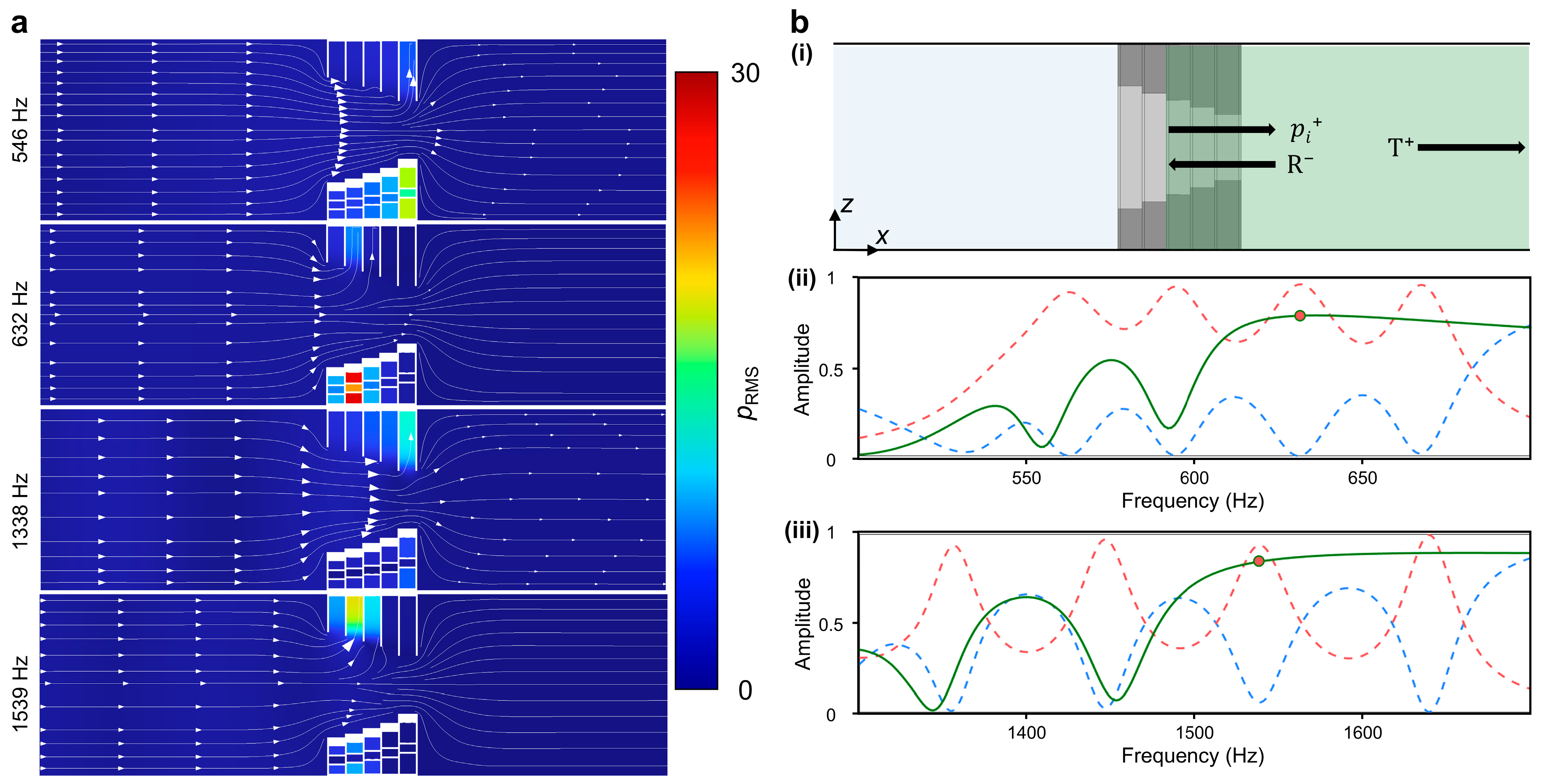
Numerical simulation for the band spectrum requires the assumption of the periodic arrangement. This analytic restriction would bring a lack of reliability in practical explanations; further studies were conducted on acoustical response in the general waveguides. Figure 5a displays the two-dimensional cut plane containing the axial line. The color map illustrates the root mean square (RMS) value of acoustic pressure, and the streamline depicts the flow of acoustic intensity. Observing the flow of acoustic intensity, a significant reduction in scale is apparent across the structure at frequencies of 632 Hz and 1539 Hz. This corresponds to the third peak of the absorption coefficient at low and high frequencies, suggesting that a significant amount of energy might be dissipated through the structures. The Din,2 layer shows the outstanding responses at this frequency, and more detailed local property will be discussed in Figure 6. In the frequencies of 546 Hz and 1539 Hz, intensity flow passes through the structure and maintains its scale. The feeble resonance was observed in the Din,5 layer, which has the lowest resonance frequency and absorption performance.
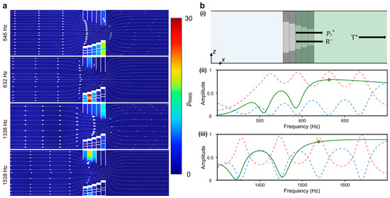
Figure 5.
Acoustical response of the simulated structure. (a) Axial plane view of the sound field at certain frequencies. Intensity streamlines and pRMS distribution fields are depicted. (b) (i) Modifications in the analysis domain (green region), where the incident wave starts at the boundary of Din,2 and Din,3 layers. Calculated reflectance (green line) is suggested with the (ii) first and (iii) second absorptive domain of full-waveguide simulation. The red and blue dashed lines correspond to the absorption coefficient and reflectance of full-waveguide simulation, respectively. The red dot indicates the reflectance of modified simulation at the specific frequency, where the third absorption peak was observed in the full-waveguide simulation.
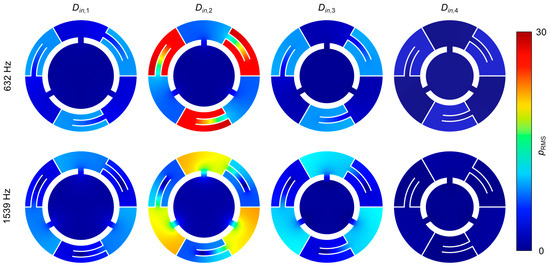
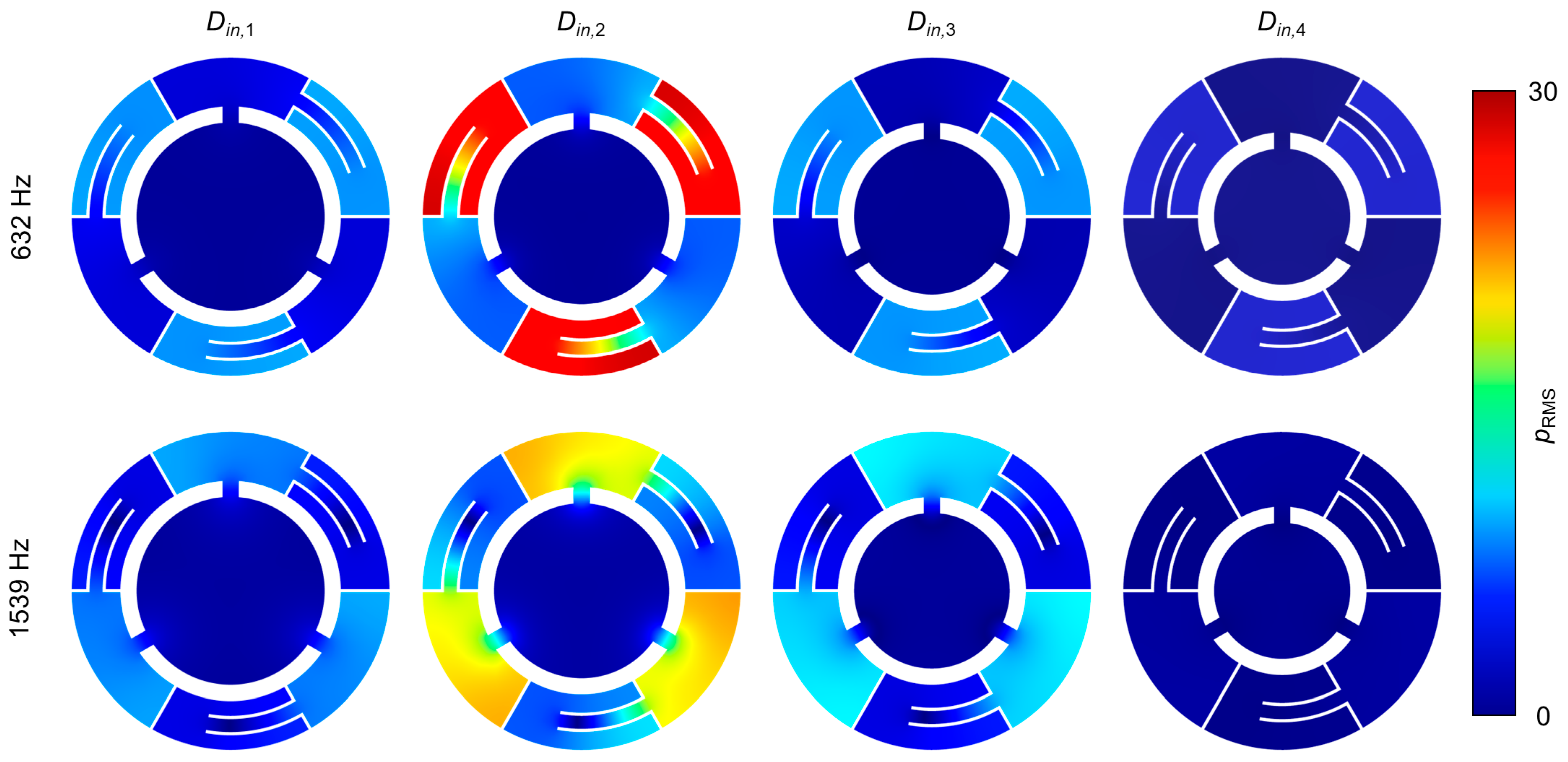
Figure 6.
Radial plane view of each layer. The color map stands for pRMS distribution under the frequency of 632 Hz and 1539 Hz.
The dissipation of intensity can be explained with the principal concepts of the designed structure: effective reflecting and critical coupling. Adjustments in analyzing domains were made by port selections, as seen in Figure 4b. This domain selection aims for delicate comprehension of non-local interactions between the layers. Strong reflection was observed at the point where the third absorption peak would be placed, as depicted in Figure 5b. These results prove that the amount of energy is reflected from the rear layer to the front layer, which is the concept of an effective reflecting wall. The activating layers in Figure 5a contain the local property of this structure with the concept of critical coupling. In the frequencies of 546 Hz and 1338 Hz, the layer of Din,5 has relatively minor excitations. This response is insufficient for critical coupling but adequate for acting as an effective reflecting wall. The first absorption peak would be placed just above this frequency, where the layer of Din,4 critically resonates. With these sequences, the four absorption peaks in low and high frequencies are generated.
Figure 6 depicts the mid-plane of each layer at the previously studied frequencies: 632 Hz and 1539 Hz. The color map illustrates the RMS value of acoustic pressure, so the part of SHR 2 responds to the lower resonance, and the part of SHR 1 responds to the higher resonance. As these frequencies are above the resonance frequency of the Din,3 layer, feeble resonances are presented as light blue color. From the strong reflection, which occurs between the Din,2 and Din,3 layer, the Din,4 layer with deep blue does not display any reactions. In the opposite direction, intensive resonances are presented in the Din,2 layer, which yields the peak of the absorption coefficient. These localized representations explain the principle of critical coupling and match well with Figure 5a.
3.3. Performance and Functionality
The designed metastructure in Figure 4b exhibits a low absorption coefficient at the local minimum points between the peaks. More closely spaced peaks would compensate for these low values but would result in a narrower bandwidth. We address this efficient-bandwidth tradeoff by varying the unit DHR in each layer. The three DHRs in each layer are labeled as DHRij, which represents DHR in ith layers and jth order in radial sequences. This subscription is also valid for its related dimensions.
The width of SHR 2 neck Wn2 was selected as the geometrical parameter and assigned, as shown in Table 2. The dimension remained constant at 4 mm for the fifth layer (i = 5) and first order (j = 1) of the remaining layer (i = 1, 2, 3, and 4). This consistency helps replicate the absorption peaks observed in the previous structure, thereby potentially allowing for additional absorption peaks with the rest selections. The other values were curated considering the distance between adjacent resonance frequencies (see details in the Supplementary Materials).
Table 2.
Geometrical parameters of Wn2,ij (unit: mm).
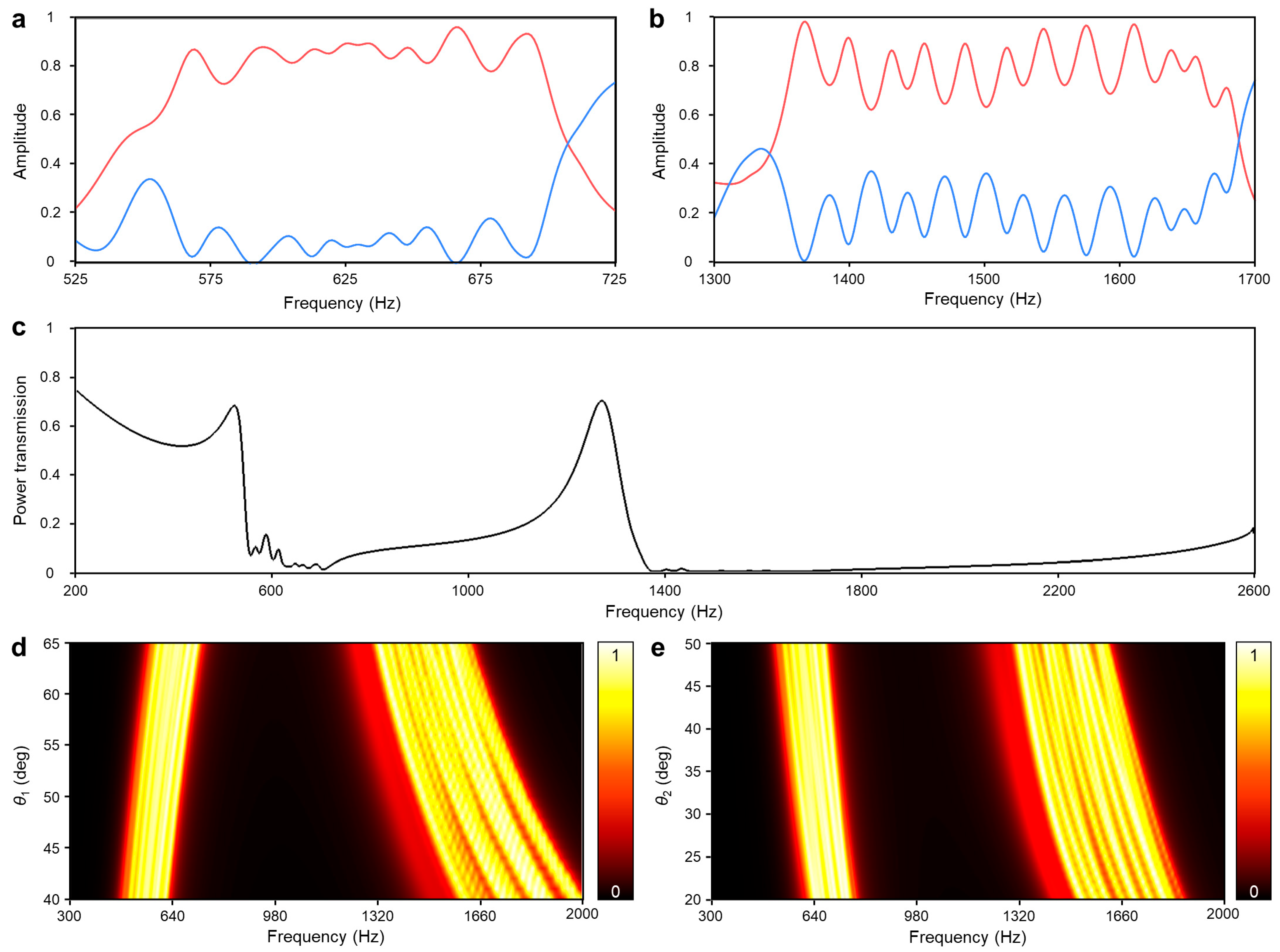
The narrow spacing between each low-frequency absorption peak results in an ambiguous but gentle absorptive band from 550 Hz to 707 Hz, as seen in Figure 7a. The evenly spaced twelve high-frequency absorption peaks create the second absorptive band from 1344 Hz to 1688 Hz in Figure 7b. After these two absorptive regions, the reflective region follows behind the Fano-like interferences. Their collaboration results in over 90% attenuation of the incident sound energy across 550 Hz to 874 Hz and the other from 1344 Hz to 2500 Hz, as shown in Figure 7c.
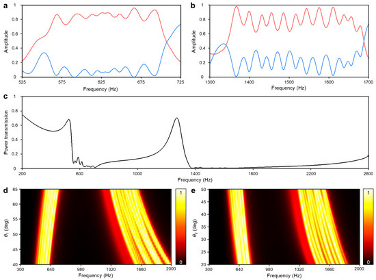
Figure 7.
The noise insulation performance of the acoustic metastructure with individually adjusted DHRs. (a) First and (b) second absorptive domains with absorption coefficient (red line) and reflectance (blue line). (c) Transmittance of the optimized structure. (d) The absorption coefficient (α) by the varying geometric parameters: circular sector angle of the first cavity θ1. (e) The absorption coefficient (α) by the varying geometric parameters: length factor of second neck θ2.
Apart from the already adjusted geometric parameters, the remaining dimensions would be fine-tuned to enhance further functionality. The entire structure exhibits a similar shifting tendency to the unit DHR when the geometric parameters are varied. The altering value of θ1 shifts the two absorptive regions in a non-parallel way, while the altering value of θ2 shifts the two absorptive regions in a parallel way, as presented in Figure 7d,e. These two distinct shifting methods could serve as valuable tools for effectively mitigating irregular or widely spreading peak noises in real-world applications.
4. Conclusions
In summary, we suggest the ventilated soundproofing structure wherein unit DHRs are arranged in symmetry-breaking configurations. The DHR exhibits great flexibility in shifting two resonance frequencies and enhancing their absorption coefficients through numerous dimension variables. At the sub-wavelength scale, each DHR layer is asymmetrically loaded in the waveguides, functioning as both an effective reflecting wall and an effective dissipator based on the frequency of the incident wave. This leads to a significant amplification of absorption performance with four peaks in the low- and high-frequency domains. By adjusting the remaining dimensions in a gradient sequence, the metastructure demonstrates two attenuation bands, comprising absorptive and reflective regions. These absorption bands, originating from unit DHRs, leverage its advantages, such as shape versatility and unparalleled frequency shifting. Thus, this study may pave the way for utilizing the controllable absorptive domains for peak noise reduction in diverse application scenarios, along with the reflective domains.
Supplementary Materials
The following supporting information can be downloaded at: https://www.mdpi.com/article/10.3390/s24051432/s1, S.1: Detailed description for numerical simulation; S.2: Detailed description for numerical simulation; S.3: Resonance frequency of the DHRs.
Author Contributions
Conceptualization: I.H., I.L. and G.Y.; methodology: I.H.; software: I.H. and I.L.; validation: I.H.; formal analysis: I.H.; investigation: I.H. and I.L.; resources: G.Y.; data curation: I.H. and I.L.; writing—original draft: I.H.; writing—review and editing: G.Y.; visualization: I.H. and I.L.; supervision: G.Y.; project administration: G.Y.; funding acquisition: G.Y. Authorship was limited to those who contributed substantially to the reported work. All authors have read and agreed to the published version of the manuscript.
Funding
This work was supported by the Research Program funded by the Seoul National University of Science and Technology.
Institutional Review Board Statement
Not applicable.
Informed Consent Statement
Not applicable.
Data Availability Statement
Data are contained within the article.
Conflicts of Interest
The authors declare no conflicts of interest.
References
- Tao, Y.; Ren, M.; Zhang, H.; Peijs, T. Recent Progress in Acoustic Materials and Noise Control Strategies—A Review. Appl. Mater. Today 2021, 24, 101141. [Google Scholar] [CrossRef]
- Mir, F.; Mandal, D.; Banerjee, S. Metamaterials for Acoustic Noise Filtering and Energy Harvesting. Sensors 2023, 23, 4227. [Google Scholar] [CrossRef] [PubMed]
- Arenas, J.P.; Crocker, M.J. Recent Trends in Porous Sound-Absorbing Materials. Sound Vib. 2010, 44, 12–17. [Google Scholar]
- Cox, T.J.; D’Antonio, P. Acoustic Absorbers and Diffusers: Theory, Design and Application, 2nd ed.; Taylor & Francis: London, UK; New York, NY, USA, 2009; ISBN 978-0-415-47174-9. [Google Scholar]
- Kumar, S.; Lee, H. The Present and Future Role of Acoustic Metamaterials for Architectural and Urban Noise Mitigations. Acoustics 2019, 1, 590–607. [Google Scholar] [CrossRef]
- Ma, G.; Sheng, P. Acoustic Metamaterials: From Local Resonances to Broad Horizons. Sci. Adv. 2016, 2, e1501595. [Google Scholar] [CrossRef] [PubMed]
- Cummer, S.A.; Christensen, J.; Alù, A. Controlling Sound with Acoustic Metamaterials. Nat. Rev. Mater. 2016, 1, 16001. [Google Scholar] [CrossRef]
- Liu, Z.; Zhang, X.; Mao, Y.; Zhu, Y.Y.; Yang, Z.; Chan, C.T.; Sheng, P. Locally Resonant Sonic Materials. Sci. New Ser. 2000, 289, 1734–1736. [Google Scholar] [CrossRef]
- Fang, N.; Xi, D.; Xu, J.; Ambati, M.; Srituravanich, W.; Sun, C.; Zhang, X. Ultrasonic Metamaterials with Negative Modulus. Nat. Mater. 2006, 5, 452–456. [Google Scholar] [CrossRef]
- Fleury, R.; Alù, A. Extraordinary Sound Transmission through Density-Near-Zero Ultranarrow Channels. Phys. Rev. Lett. 2013, 111, 055501. [Google Scholar] [CrossRef]
- Cselyuszka, N.; Sečujski, M.; Crnojević Bengin, V. Compressibility-near-Zero Acoustic Metamaterial. Phys. Lett. A 2014, 378, 1153–1156. [Google Scholar] [CrossRef]
- Lee, S.H.; Park, C.M.; Seo, Y.M.; Wang, Z.G.; Kim, C.K. Composite Acoustic Medium with Simultaneously Negative Density and Modulus. Phys. Rev. Lett. 2010, 104, 054301. [Google Scholar] [CrossRef] [PubMed]
- Zhang, S.; Yin, L.; Fang, N. Focusing Ultrasound with an Acoustic Metamaterial Network. Phys. Rev. Lett. 2009, 102, 194301. [Google Scholar] [CrossRef] [PubMed]
- Li, Y.; Yu, G.; Liang, B.; Zou, X.; Li, G.; Cheng, S.; Cheng, J. Three-Dimensional Ultrathin Planar Lenses by Acoustic Metamaterials. Sci. Rep. 2014, 4, 6830. [Google Scholar] [CrossRef] [PubMed]
- Ma, F.; Huang, Z.; Liu, C.; Wu, J.H. Acoustic Focusing and Imaging via Phononic Crystal and Acoustic Metamaterials. J. Appl. Phys. 2022, 131, 011103. [Google Scholar] [CrossRef]
- Chen, H.; Chan, C.T. Acoustic Cloaking and Transformation Acoustics. J. Phys. D Appl. Phys. 2010, 43, 113001. [Google Scholar] [CrossRef]
- Zhu, X.; Liang, B.; Kan, W.; Zou, X.; Cheng, J. Acoustic Cloaking by a Superlens with Single-Negative Materials. Phys. Rev. Lett. 2011, 106, 014301. [Google Scholar] [CrossRef] [PubMed]
- Zigoneanu, L.; Popa, B.-I.; Cummer, S.A. Three-Dimensional Broadband Omnidirectional Acoustic Ground Cloak. Nat. Mater. 2014, 13, 352–355. [Google Scholar] [CrossRef]
- Zhang, J.; Rui, W.; Ma, C.; Cheng, Y.; Liu, X.; Christensen, J. Remote Whispering Metamaterial for Non-Radiative Transceiving of Ultra-Weak Sound. Nat. Commun. 2021, 12, 3670. [Google Scholar] [CrossRef]
- Wu, K.; Liu, J.-J.; Ding, Y.; Wang, W.; Liang, B.; Cheng, J.-C. Metamaterial-Based Real-Time Communication with High Information Density by Multipath Twisting of Acoustic Wave. Nat. Commun. 2022, 13, 5171. [Google Scholar] [CrossRef]
- Zhu, Y.-F.; Zou, X.-Y.; Liang, B.; Cheng, J.-C. Acoustic One-Way Open Tunnel by Using Metasurface. Appl. Phys. Lett. 2015, 107, 113501. [Google Scholar] [CrossRef]
- Cai, X.; Guo, Q.; Hu, G.; Yang, J. Ultrathin Low-Frequency Sound Absorbing Panels Based on Coplanar Spiral Tubes or Coplanar Helmholtz Resonators. Appl. Phys. Lett. 2014, 105, 121901. [Google Scholar] [CrossRef]
- Tang, Y.; Ren, S.; Meng, H.; Xin, F.; Huang, L.; Chen, T.; Zhang, C.; Lu, T.J. Hybrid Acoustic Metamaterial as Super Absorber for Broadband Low-Frequency Sound. Sci. Rep. 2017, 7, 43340. [Google Scholar] [CrossRef] [PubMed]
- Wang, X.; Luo, X.; Yang, B.; Huang, Z. Ultrathin and Durable Open Metamaterials for Simultaneous Ventilation and Sound Reduction. Appl. Phys. Lett. 2019, 115, 171902. [Google Scholar] [CrossRef]
- Xiang, X.; Wu, X.; Li, X.; Wu, P.; He, H.; Mu, Q.; Wang, S.; Huang, Y.; Wen, W. Ultra-Open Ventilated Metamaterial Absorbers for Sound-Silencing Applications in Environment with Free Air Flows. Extrem. Mech. Lett. 2020, 39, 100786. [Google Scholar] [CrossRef]
- Nguyen, H.; Wu, Q.; Xu, X.; Chen, H.; Tracy, S.; Huang, G. Broadband Acoustic Silencer with Ventilation Based on Slit-Type Helmholtz Resonators. Appl. Phys. Lett. 2020, 117, 134103. [Google Scholar] [CrossRef]
- Liu, C.; Wang, H.; Liang, B.; Cheng, J.; Lai, Y. Low-Frequency and Broadband Muffler via Cascaded Labyrinthine Metasurfaces. Appl. Phys. Lett. 2022, 120, 231702. [Google Scholar] [CrossRef]
- Ghaffarivardavagh, R.; Nikolajczyk, J.; Anderson, S.; Zhang, X. Ultra-Open Acoustic Metamaterial Silencer Based on Fano-like Interference. Phys. Rev. B 2019, 99, 024302. [Google Scholar] [CrossRef]
- Sun, M.; Fang, X.; Mao, D.; Wang, X.; Li, Y. Broadband Acoustic Ventilation Barriers. Phys. Rev. Appl. 2020, 13, 044028. [Google Scholar] [CrossRef]
- Chen, A.; Zhao, X.; Yang, Z.; Anderson, S.; Zhang, X. Broadband Labyrinthine Acoustic Insulator. Phys. Rev. Appl. 2022, 18, 064057. [Google Scholar] [CrossRef]
- Tang, Y.; Liang, B.; Lin, S. Broadband Ventilated Meta-Barrier Based on the Synergy of Mode Superposition and Consecutive Fano Resonances. J. Acoust. Soc. Am. 2022, 152, 2412–2418. [Google Scholar] [CrossRef]
- Zhu, Y.; Dong, R.; Mao, D.; Wang, X.; Li, Y. Nonlocal Ventilating Metasurfaces. Phys. Rev. Appl. 2023, 19, 014067. [Google Scholar] [CrossRef]
- Yang, J.; Lee, J.S.; Lee, H.R.; Kang, Y.J.; Kim, Y.Y. Slow-Wave Metamaterial Open Panels for Efficient Reduction of Low-Frequency Sound Transmission. Appl. Phys. Lett. 2018, 112, 091901. [Google Scholar] [CrossRef]
- Xiao, Z.; Gao, P.; Wang, D.; He, X.; Wu, L. Ventilated Metamaterials for Broadband Sound Insulation and Tunable Transmission at Low Frequency. Extrem. Mech. Lett. 2021, 46, 101348. [Google Scholar] [CrossRef]
- Kumar, S.; Lee, H.P. Labyrinthine Acoustic Metastructures Enabling Broadband Sound Absorption and Ventilation. Appl. Phys. Lett. 2020, 116, 134103. [Google Scholar] [CrossRef]
- Kumar, S.; Xiang, T.B.; Lee, H.P. Ventilated Acoustic Metamaterial Window Panels for Simultaneous Noise Shielding and Air Circulation. Appl. Acoust. 2020, 159, 107088. [Google Scholar] [CrossRef]
- Gao, Y.-X.; Cheng, Y.; Liang, B.; Li, Y.; Yang, J.; Cheng, J.-C. Acoustic Skin Meta-Muffler. Sci. China Phys. Mech. Astron. 2021, 64, 294311. [Google Scholar] [CrossRef]
- Dong, R.; Mao, D.; Wang, X.; Li, Y. Ultrabroadband Acoustic Ventilation Barriers via Hybrid-Functional Metasurfaces. Phys. Rev. Appl. 2021, 15, 024044. [Google Scholar] [CrossRef]
- Xu, M.B.; Selamet, A.; Kim, H. Dual Helmholtz Resonator. Appl. Acoust. 2010, 71, 822–829. [Google Scholar] [CrossRef]
- Jiménez, N. Acoustic Waves in Periodic Structures, Metamaterials, and Porous Media: From Fundamentals to Industrial Applications, 4th ed.; Springer: Cham, Switzerland, 2022; ISBN 978-3-030-84300-7. [Google Scholar]
- Kinsler, L.E.; Frey, A.R. Fundamentals of Acoustics, 4th ed.; John Wiley and Sons: New York, NY, USA, 2000; ISBN 978-0-471-84789-2. [Google Scholar]
- Sagartzazu, X.; Hervella-Nieto, L.; Pagalday, J.M. Review in Sound Absorbing Materials. Arch. Computat. Methods Eng. 2008, 15, 311–342. [Google Scholar] [CrossRef]
- Merkel, A.; Theocharis, G.; Richoux, O.; Romero-García, V.; Pagneux, V. Control of Acoustic Absorption in One-Dimensional Scattering by Resonant Scatterers. Appl. Phys. Lett. 2015, 107, 244102. [Google Scholar] [CrossRef]
- Jiménez, N.; Romero-García, V.; Pagneux, V.; Groby, J.-P. Rainbow-Trapping Absorbers: Broadband, Perfect and Asymmetric Sound Absorption by Subwavelength Panels for Transmission Problems. Sci. Rep. 2017, 7, 13595. [Google Scholar] [CrossRef]

Disclaimer/Publisher’s Note: The statements, opinions and data contained in all publications are solely those of the individual author(s) and contributor(s) and not of MDPI and/or the editor(s). MDPI and/or the editor(s) disclaim responsibility for any injury to people or property resulting from any ideas, methods, instructions or products referred to in the content. |
© 2024 by the authors. Licensee MDPI, Basel, Switzerland. This article is an open access article distributed under the terms and conditions of the Creative Commons Attribution (CC BY) license (https://creativecommons.org/licenses/by/4.0/).