

Choice of Piezoelectric Element over Accelerometer for an Energy-Autonomous Shoe-Based System


Abstract
1. Introduction
1.1. Shoe-Based Human Gait Acquisition
1.2. Power Management of Smart Shoe Insole
1.3. Proposed Work
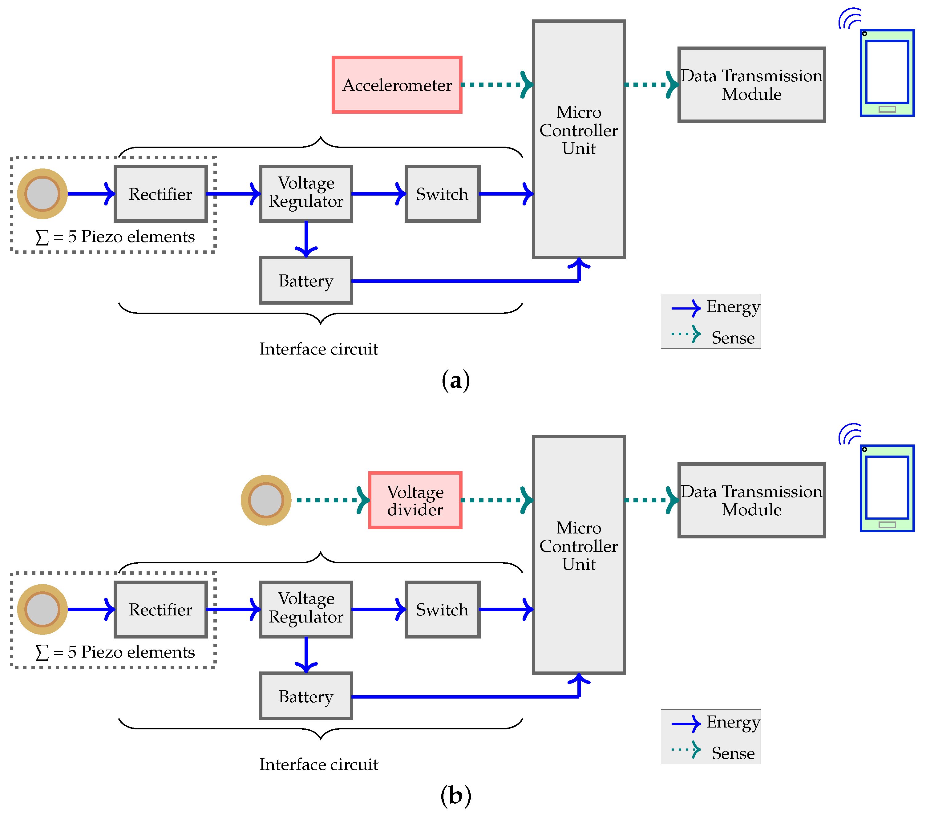
2. System Design
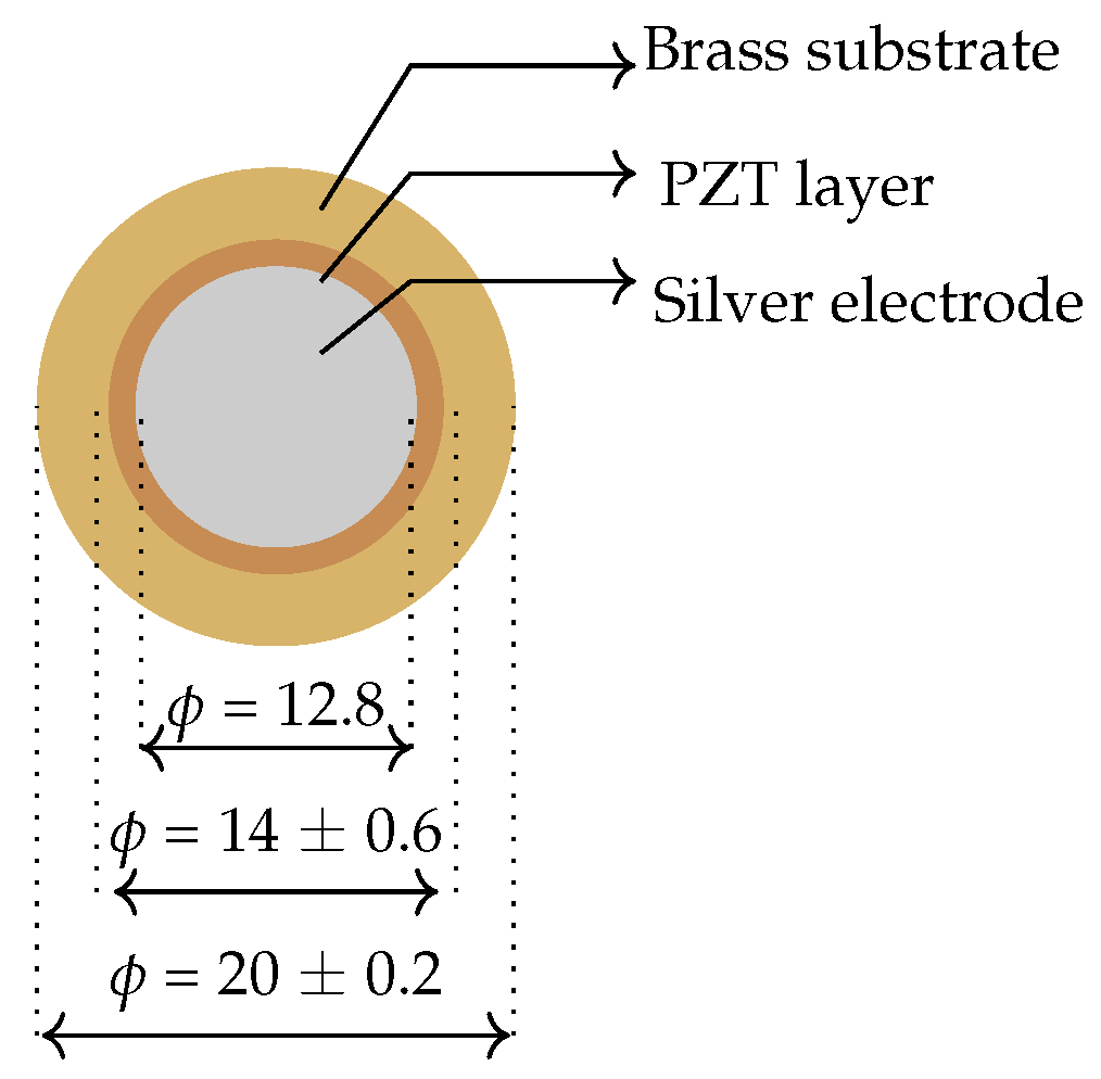
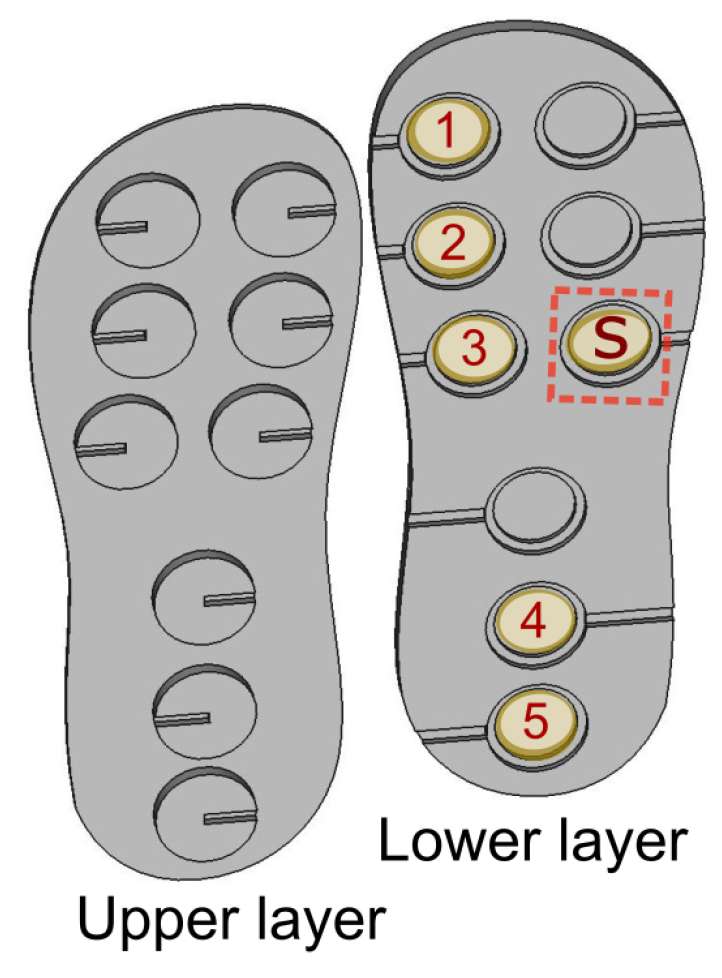
2.1. Sensor
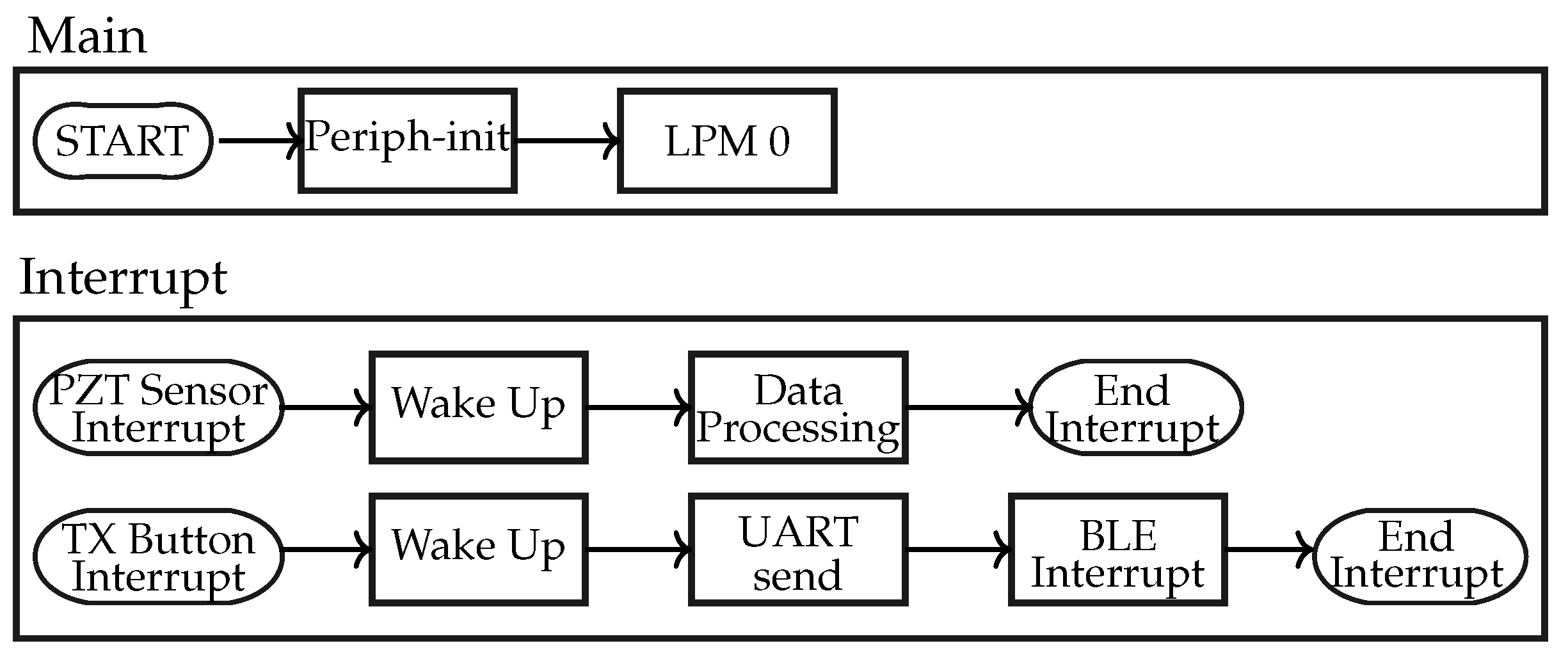
2.2. Microcontroller Unit (MCU)
2.3. Data Transmission Module
2.4. Piezoelectric Energy Harvesters
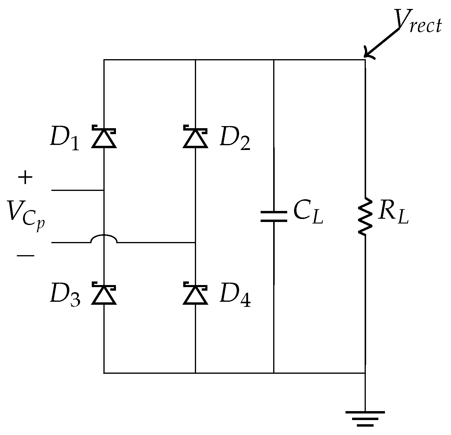
2.5. Interface Circuit
2.5.1. Rectifier
2.5.2. Voltage Regulator
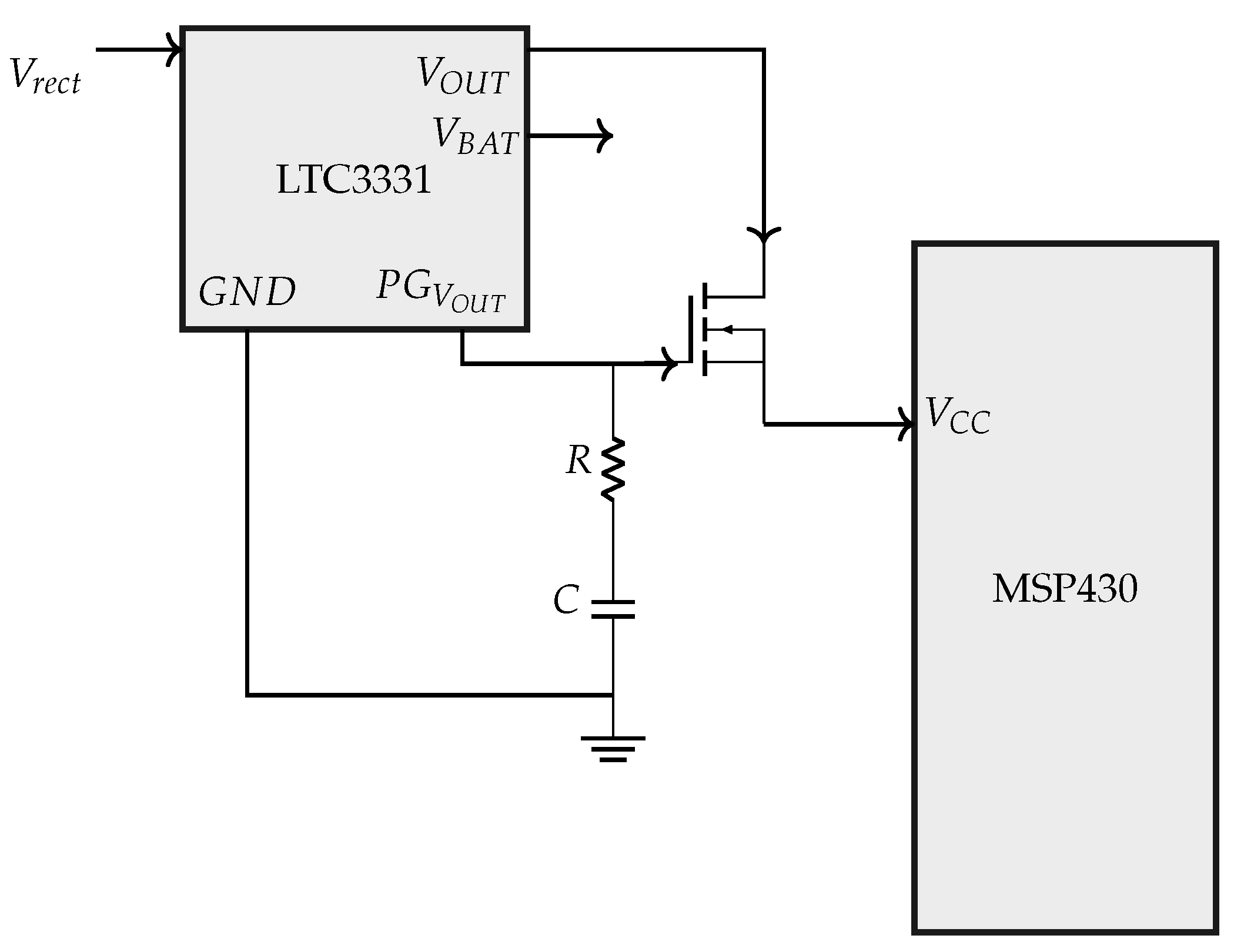
2.5.3. Switch
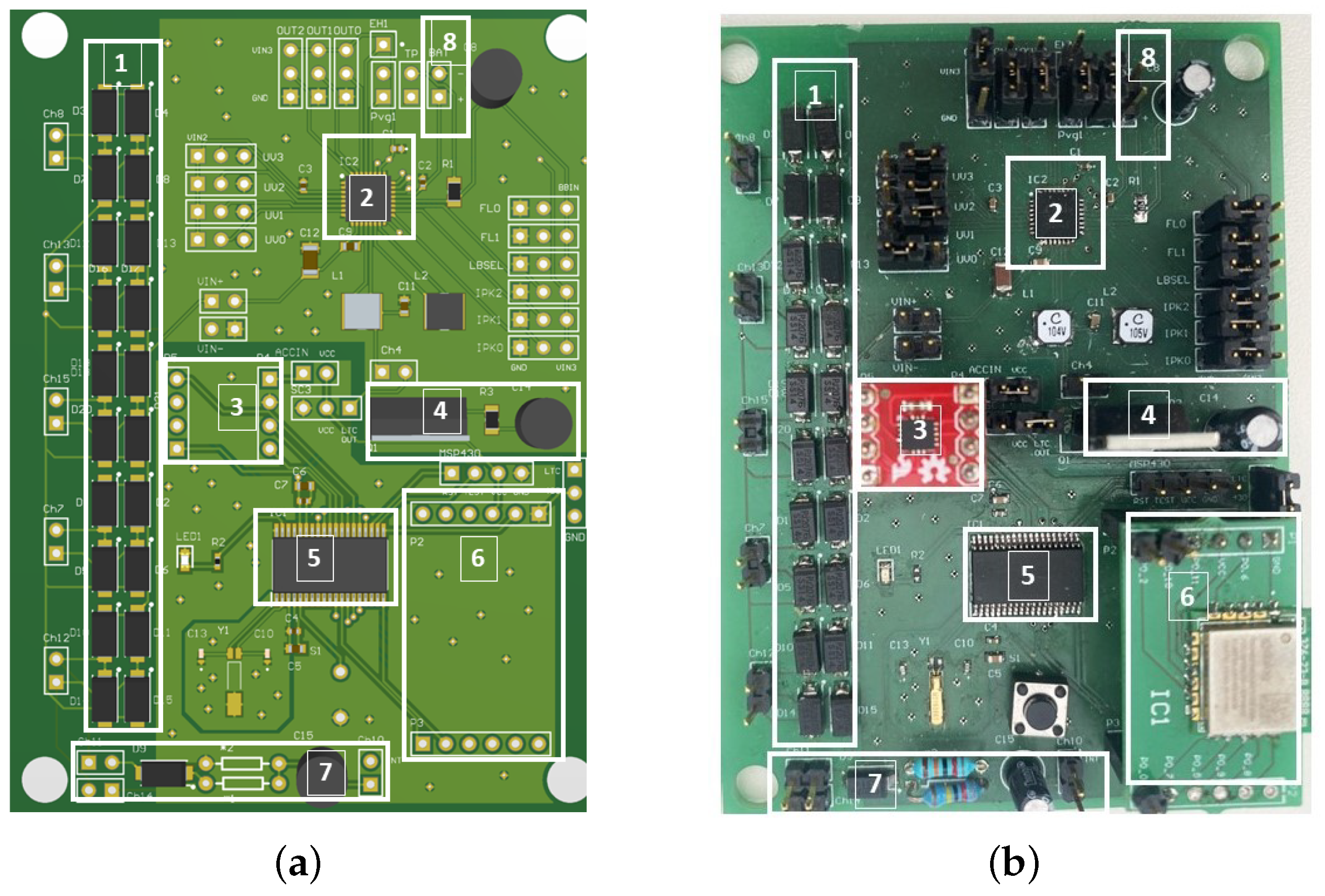
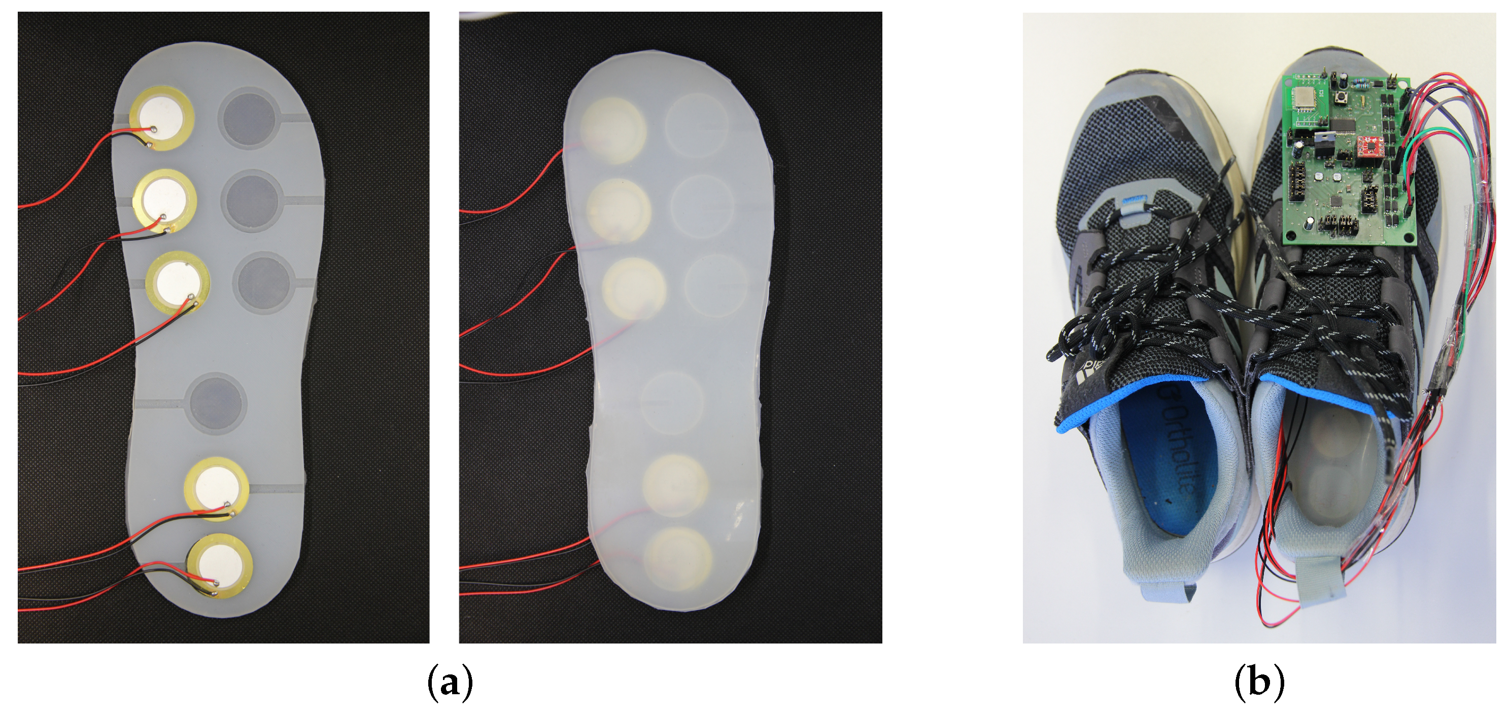
2.6. Final System Design
3. Sensor Data Acquisition
3.1. Strategy 1: Accelerometer plus BLE Broadcaster
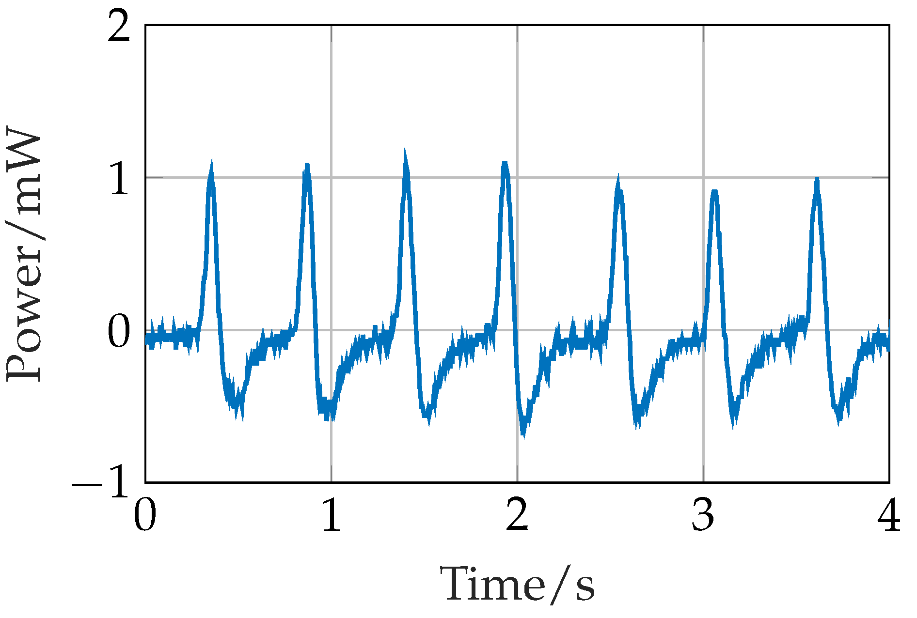
3.2. Strategy 2: Piezoelectric Sensor + BLE Broadcaster
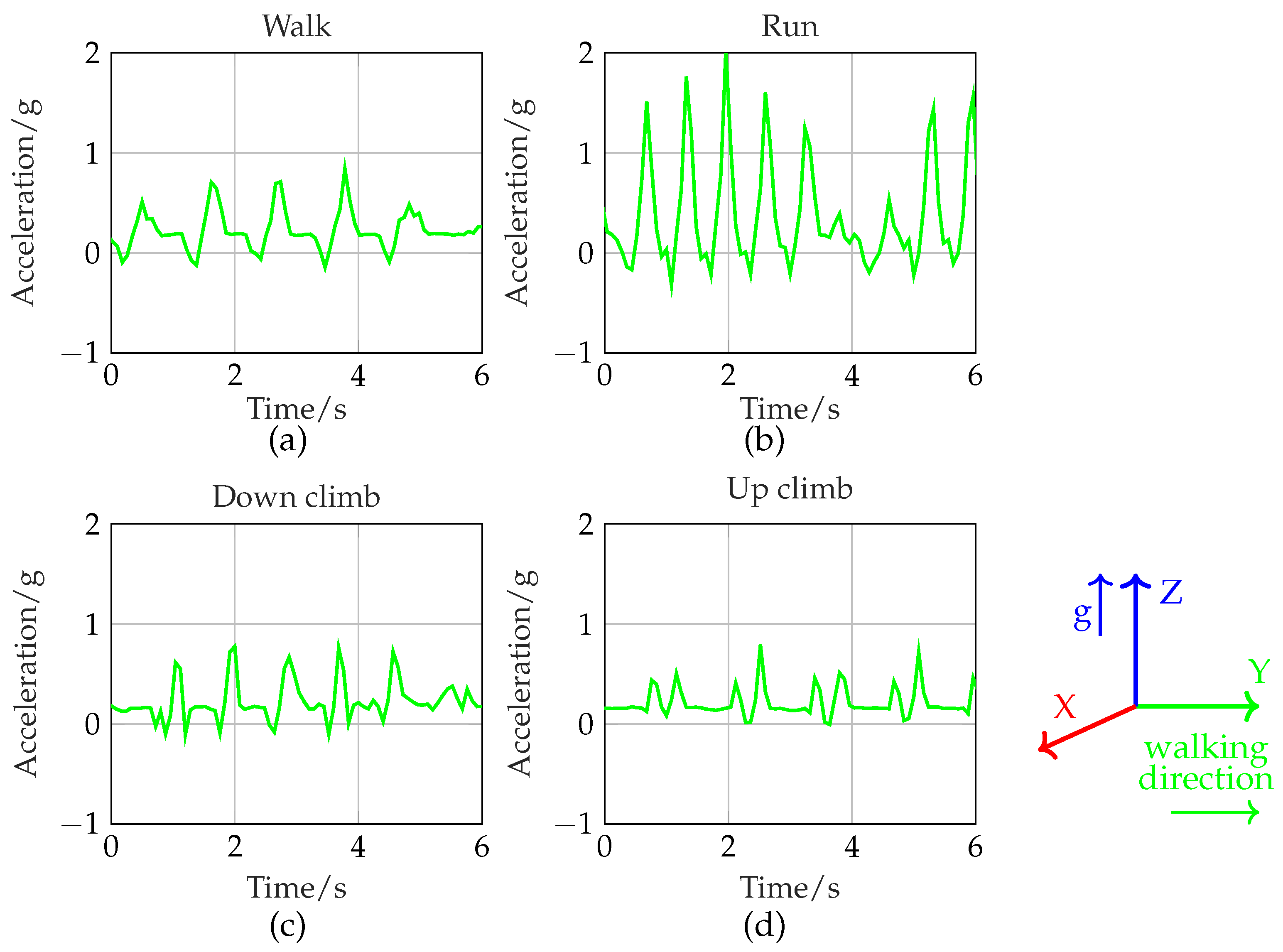
Gait Signal
3.3. Power Calculation
3.4. Accuracy Calculation
4. Results and Discussion
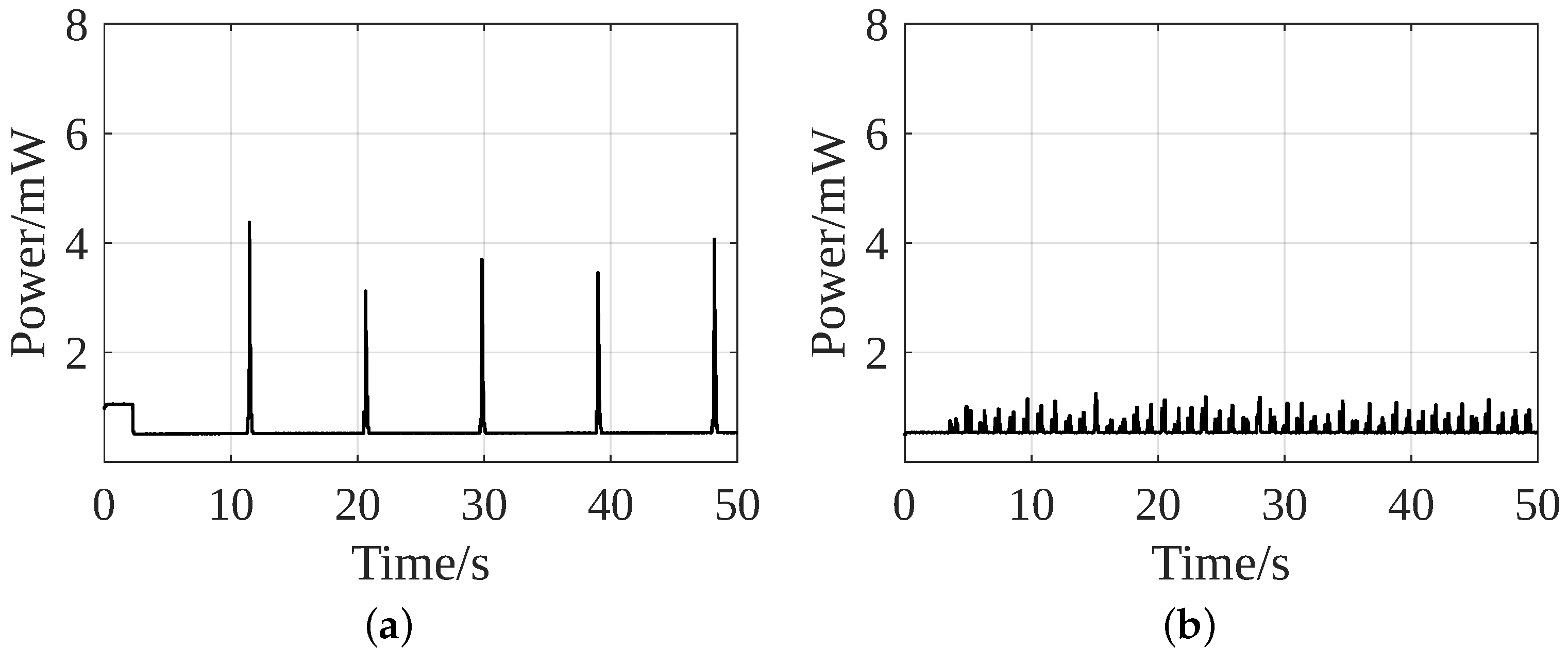
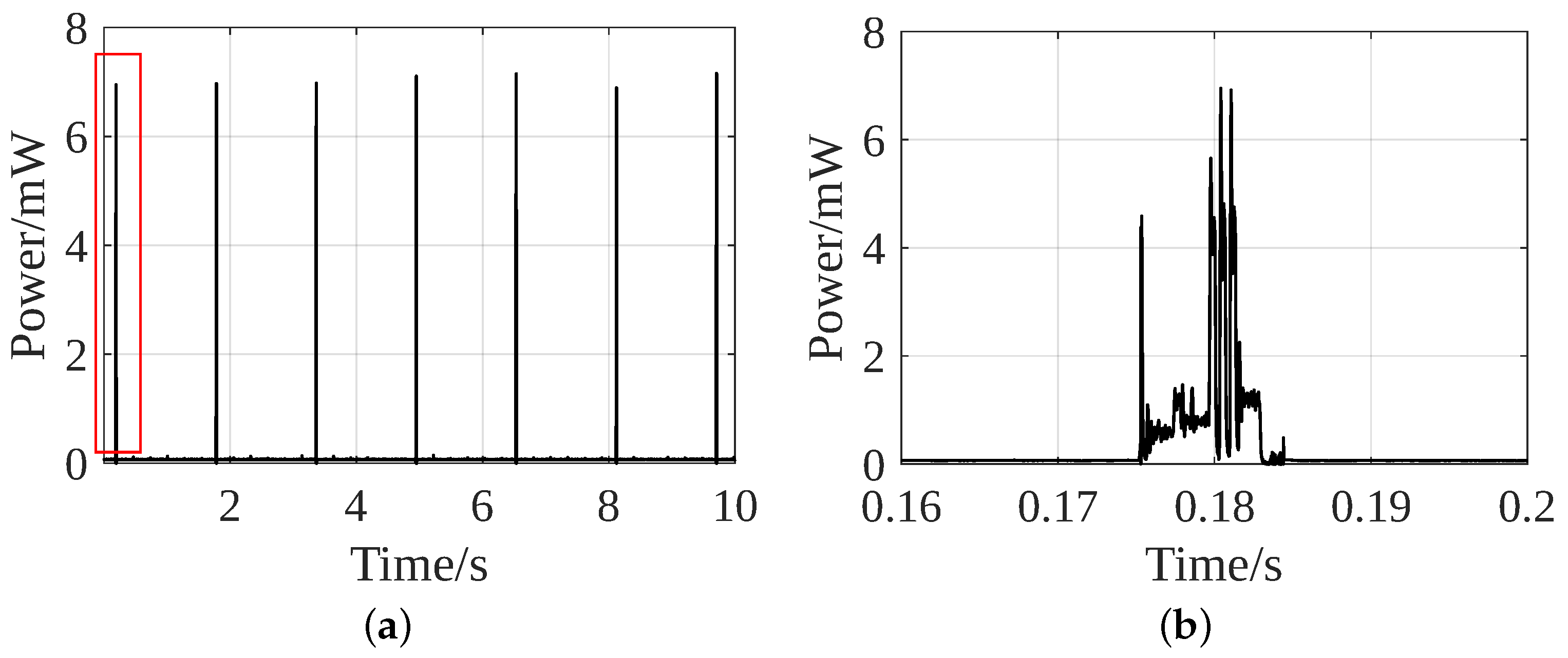
4.1. Power Consumption during Data Acquisition, Processing and Transmission
4.2. Accuracy Comparison of Both Strategies
4.3. Output of Interface Circuit
5. Conclusions
Author Contributions
Funding
Data Availability Statement
Conflicts of Interest
References
- Brophy, K.; Davies, S.; Olenik, S.; Çotur, Y.; Ming, D.; Van Zalk, N.; O’Hare, D.; Guder, F.; Yetisen, A.K. The Future of Wearable Technologies; Imperial College London: London, UK, 2021. [Google Scholar]
- Ates, H.C.; Nguyen, P.Q.; Gonzalez-Macia, L.; Morales-Narváez, E.; Güder, F.; Collins, J.J.; Dincer, C. End-to-end design of wearable sensors. Nat. Rev. Mater. 2022, 7, 887–907. [Google Scholar] [CrossRef] [PubMed]
- Ali, A.; Shaukat, H.; Bibi, S.; Altabey, W.A.; Noori, M.; Kouritem, S.A. Recent progress in energy harvesting systems for wearable technology. Energy Strategy Rev. 2023, 49, 101124. [Google Scholar] [CrossRef]
- Channa, A.; Popescu, N.; Skibinska, J.; Burget, R. The rise of wearable devices during the COVID-19 pandemic: A systematic review. Sensors 2021, 21, 5787. [Google Scholar] [CrossRef] [PubMed]
- Wang, X.; Yu, H.; Kold, S.; Rahbek, O.; Bai, S. Wearable sensors for activity monitoring and motion control: A review. Biomim. Intell. Robot. 2023, 3, 100089. [Google Scholar] [CrossRef]
- De Fazio, R.; Mastronardi, V.M.; De Vittorio, M.; Visconti, P. Wearable Sensors and Smart Devices to Monitor Rehabilitation Parameters and Sports Performance: An Overview. Sensors 2023, 23, 1856. [Google Scholar] [CrossRef] [PubMed]
- Surantha, N.; Atmaja, P.; Wicaksono, M. A review of wearable internet-of-things device for healthcare. Procedia Comput. Sci. 2021, 179, 936–943. [Google Scholar] [CrossRef]
- Gao, S.; Chen, J.L.; Dai, Y.N.; Wang, R.; Kang, S.B.; Xu, L.J. Piezoelectric-based insole force sensing for gait analysis in the Internet of Health Things. IEEE Consum. Electron. Mag. 2020, 10, 39–44. [Google Scholar] [CrossRef]
- Almuteb, I.; Hua, R.; Wang, Y. Smart insoles review over the last two decade: Applications, potentials, and future. Smart Health 2022, 25, 100301. [Google Scholar] [CrossRef]
- Iqbal, S.M.; Mahgoub, I.; Du, E.; Leavitt, M.A.; Asghar, W. Advances in healthcare wearable devices. NPJ Flex. Electron. 2021, 5, 9. [Google Scholar] [CrossRef]
- Stavropoulos, T.G.; Papastergiou, A.; Mpaltadoros, L.; Nikolopoulos, S.; Kompatsiaris, I. IoT wearable sensors and devices in elderly care: A literature review. Sensors 2020, 20, 2826. [Google Scholar] [CrossRef]
- Meng, K.; Zhao, S.; Zhou, Y.; Wu, Y.; Zhang, S.; He, Q.; Wang, X.; Zhou, Z.; Fan, W.; Tan, X.; et al. A wireless textile-based sensor system for self-powered personalized health care. Matter 2020, 2, 896–907. [Google Scholar] [CrossRef]
- Haghi, M.; Thurow, K.; Stoll, R. Wearable devices in medical internet of things: Scientific research and commercially available devices. Healthc. Inform. Res. 2017, 23, 4–15. [Google Scholar] [CrossRef]
- Pasluosta, C.F.; Gassner, H.; Winkler, J.; Klucken, J.; Eskofier, B.M. An emerging era in the management of Parkinson’s disease: Wearable technologies and the internet of things. IEEE J. Biomed. Health Inform. 2015, 19, 1873–1881. [Google Scholar] [CrossRef] [PubMed]
- De Fazio, R.; De Vittorio, M.; Visconti, P. Innovative IoT solutions and wearable sensing systems for monitoring human biophysical parameters: A review. Electronics 2021, 10, 1660. [Google Scholar] [CrossRef]
- Islam, S.M.R.; Kwak, D.; Kabir, M.H.; Hossain, M.; Kwak, K.S. The Internet of Things for Health Care: A Comprehensive Survey. IEEE Access 2015, 3, 678–708. [Google Scholar] [CrossRef]
- Huang, B.; Chen, M.; Shi, X.; Xu, Y. Gait Event Detection with Intelligent Shoes. In Proceedings of the 2007 International Conference on Information Acquisition, Seogwipo, Republic of Korea, 8–11 July 2007; pp. 579–584. [Google Scholar]
- Tao, W.; Liu, T.; Zheng, R.; Feng, H. Gait analysis using wearable sensors. Sensors 2012, 12, 2255–2283. [Google Scholar] [CrossRef]
- Eskofier, B.M.; Lee, S.I.; Baron, M.; Simon, A.; Martindale, C.F.; Gaßner, H.; Klucken, J. An overview of smart shoes in the internet of health things: Gait and mobility assessment in health promotion and disease monitoring. Appl. Sci. 2017, 7, 986. [Google Scholar] [CrossRef]
- Lord, S.; Galna, B.; Rochester, L. Moving forward on gait measurement: Toward a more refined approach. Mov. Disord. 2013, 28, 1534–1543. [Google Scholar] [CrossRef]
- Zhu, G.; Bai, P.; Chen, J.; Wang, Z.L. Power-generating shoe insole based on triboelectric nanogenerators for self-powered consumer electronics. Nano Energy 2013, 2, 688–692. [Google Scholar] [CrossRef]
- Biswas, N.; Chakrabarti, S.; Jones, L.D.; Ashili, S. Smart wearables addressing gait disorders: A review. Mater. Today Commun. 2023, 35, 106250. [Google Scholar] [CrossRef]
- Argañarás, J.G.; Wong, Y.T.; Begg, R.; Karmakar, N.C. State-of-the-art wearable sensors and possibilities for radar in fall prevention. Sensors 2021, 21, 6836. [Google Scholar] [CrossRef] [PubMed]
- Chaitow, L. Modern Neuromuscular Techniques; Elsevier Health Sciences: Amsterdam, The Netherlands, 2010. [Google Scholar]
- Delgado-Gonzalo, R.; Hubbard, J.; Renevey, P.; Lemkaddem, A.; Vellinga, Q.; Ashby, D.; Willardson, J.; Bertschi, M. Real-time gait analysis with accelerometer-based smart shoes. In Proceedings of the 2017 39th Annual International Conference of the IEEE Engineering in Medicine and Biology Society (EMBC), Jeju, Republic of Korea, 11–15 July 2017; pp. 148–148c. [Google Scholar]
- Guo, Y.; Zhao, G.; Liu, Q.; Mei, Z.; Ivanov, K.; Wang, L. Balance and knee extensibility evaluation of hemiplegic gait using an inertial body sensor network. Biomed. Eng. Online 2013, 12, 83. [Google Scholar] [CrossRef] [PubMed]
- Paton, J.S.; Stenhouse, E.A.; Bruce, G.; Zahra, D.; Jones, R.B. A comparison of customised and prefabricated insoles to reduce risk factors for neuropathic diabetic foot ulceration: A participant-blinded randomised controlled trial. J. Foot Ankle Res. 2012, 5, 31. [Google Scholar] [CrossRef] [PubMed]
- Strohrmann, C.; Patel, S.; Mancinelli, C.; Deming, L.C.; Chu, J.J.; Greenwald, R.; Tröster, G.; Bonato, P. Automated assessment of gait deviations in children with cerebral palsy using a sensorized shoe and active shape models. In Proceedings of the 2013 IEEE International Conference on Body Sensor Networks, Cambridge, MA, USA, 6–9 May 2013; pp. 1–6. [Google Scholar]
- Wu, G.; Ladin, Z. The study of kinematic transients in locomotion using the integrated kinematic sensor. IEEE Trans. Rehabil. Eng. 1996, 4, 193–200. [Google Scholar] [PubMed]
- Miyazaki, S. Long-term unrestrained measurement of stride length and walking velocity utilizing a piezoelectric gyroscope. IEEE Trans. Biomed. Eng. 1997, 44, 753–759. [Google Scholar] [CrossRef] [PubMed]
- Anwary, A.R.; Yu, H.; Vassallo, M. Optimal foot location for placing wearable IMU sensors and automatic feature extraction for gait analysis. IEEE Sens. J. 2018, 18, 2555–2567. [Google Scholar] [CrossRef]
- Mariani, B.; Jiménez, M.C.; Vingerhoets, F.J.G.; Aminian, K. On-Shoe Wearable Sensors for Gait and Turning Assessment of Patients With Parkinson’s Disease. IEEE Trans. Biomed. Eng. 2013, 60, 155–158. [Google Scholar] [CrossRef] [PubMed]
- Seneviratne, S.; Hu, Y.; Nguyen, T.; Lan, G.; Khalifa, S.; Thilakarathna, K.; Hassan, M.; Seneviratne, A. A survey of wearable devices and challenges. IEEE Commun. Surv. Tutor. 2017, 19, 2573–2620. [Google Scholar] [CrossRef]
- Pacelli, M.; Loriga, G.; Taccini, N.; Paradiso, R. Sensing fabrics for monitoring physiological and biomechanical variables: E-textile solutions. In Proceedings of the 2006 3rd IEEE/EMBS International Summer School on Medical Devices and Biosensors, Cambridge, MA, USA, 4–6 September 2006; pp. 1–4. [Google Scholar]
- Ellis, R.J.; Ng, Y.S.; Zhu, S.; Tan, D.M.; Anderson, B.; Schlaug, G.; Wang, Y. A validated smartphone-based assessment of gait and gait variability in Parkinson’s disease. PLoS ONE 2015, 10, e0141694. [Google Scholar] [CrossRef]
- Zhu, H.; Maalej, N.; Webster, J.G.; Tompkins, W.J.; Bach-y Rita, P.; Wertsch, J.J. An umbilical data-acquisition system for measuring pressures between the foot and shoe. IEEE Trans. Biomed. Eng. 1990, 37, 908–911. [Google Scholar] [CrossRef]
- Zhu, H.; Wertsch, J.J.; Harris, G.F.; Loftsgaarden, J.D.; Price, M.B. Foot pressure distribution during walking and shuffling. Arch. Phys. Med. Rehabil. 1991, 72, 390–397. [Google Scholar] [PubMed]
- Zhu, H.; Wertsch, J.J.; Harris, G.F.; Alba, H.M.; Price, M.B. Sensate and insensate in-shoe plantar pressures. Arch. Phys. Med. Rehabil. 1993, 74, 1362–1368. [Google Scholar] [CrossRef]
- Hausdorff, J.M.; Ladin, Z.; Wei, J.Y. Footswitch system for measurement of the temporal parameters of gait. J. Biomech. 1995, 28, 347–351. [Google Scholar] [CrossRef]
- Hausdorff, J.; Zemany, L.; Peng, C.K.; Goldberger, A. Maturation of gait dynamics: Stride-to-stride variability and its temporal organization in children. J. Appl. Physiol. 1999, 86, 1040–1047. [Google Scholar] [CrossRef] [PubMed]
- Hausdorff, J.M.; Rios, D.A.; Edelberg, H.K. Gait variability and fall risk in community-living older adults: A 1-year prospective study. Arch. Phys. Med. Rehabil. 2001, 82, 1050–1056. [Google Scholar] [CrossRef]
- Lechal. 2016. Available online: https://www.lechal.com/ (accessed on 10 April 2024).
- Sensoria. 2016. Available online: https://www.sensoriafitness.com/ (accessed on 10 April 2024).
- Lin, F.; Wang, A.; Zhuang, Y.; Tomita, M.R.; Xu, W. Smart insole: A wearable sensor device for unobtrusive gait monitoring in daily life. IEEE Trans. Ind. Inform. 2016, 12, 2281–2291. [Google Scholar] [CrossRef]
- Shu, L.; Hua, T.; Wang, Y.; Li, Q.; Feng, D.D.; Tao, X. In-shoe plantar pressure measurement and analysis system based on fabric pressure sensing array. IEEE Trans. Inf. Technol. Biomed. 2010, 14, 767–775. [Google Scholar]
- Tsai, T.M.; Lee, S.Y.; Chang, S.J. Detection system for capacitive plantar pressure monitoring. IEEE Access 2020, 8, 42633–42655. [Google Scholar] [CrossRef]
- Chen, D.; Cai, Y.; Huang, M.C. Customizable pressure sensor array: Design and evaluation. IEEE Sens. J. 2018, 18, 6337–6344. [Google Scholar] [CrossRef]
- Bhongade, P.; Girhay, S.; Sheikh, A.M.; Ghata, R.; Ambadkar, S.; Dusane, C. Internet of Things-Enabled Smart Shoes for Blind People. In Proceedings of the 2022 IEEE Delhi Section Conference (DELCON), New Delhi, India, 11–13 February 2022; pp. 1–9. [Google Scholar]
- Nanduri, S.; Umamaheswari, E.; Kishore, R.; Ajaykumar, M. Smart Bottine for autistic people. Mater. Today Proc. 2022, 62, 4788–4794. [Google Scholar] [CrossRef]
- Hua, R.; Wang, Y. Monitoring insole (MONI): A low power solution toward daily gait monitoring and analysis. IEEE Sens. J. 2019, 19, 6410–6420. [Google Scholar] [CrossRef]
- Song, Y.; Min, J.; Yu, Y.; Wang, H.; Yang, Y.; Zhang, H.; Gao, W. Wireless battery-free wearable sweat sensor powered by human motion. Sci. Adv. 2020, 6, eaay9842. [Google Scholar] [CrossRef] [PubMed]
- Torah, R.; Glynne-Jones, P.; Tudor, M.; O’donnell, T.; Roy, S.; Beeby, S. Self-powered autonomous wireless sensor node using vibration energy harvesting. Meas. Sci. Technol. 2008, 19, 125202. [Google Scholar] [CrossRef]
- Zeng, X.; Peng, R.; Fan, Z.; Lin, Y. Self-powered and wearable biosensors for healthcare. Mater. Today Energy 2022, 23, 100900. [Google Scholar] [CrossRef]
- Wang, X.; Liu, X.; Zhang, J.; Liang, L.; Li, M.; Yao, H.; Hou, T.; Wu, Y.; Zi, Y.; Zheng, H. A high-applicability, high-durability wearable hybrid nanogenerator with magnetic suspension structure toward health monitoring applications. Nano Energy 2022, 103, 107774. [Google Scholar] [CrossRef]
- Zou, Y.; Libanori, A.; Xu, J.; Nashalian, A.; Chen, J. Triboelectric nanogenerator enabled smart shoes for wearable electricity generation. Research 2020, 2020, 7158953. [Google Scholar] [CrossRef]
- Rong, G.; Zheng, Y.; Sawan, M. Energy solutions for wearable sensors: A review. Sensors 2021, 21, 3806. [Google Scholar] [CrossRef]
- Starner, T. Human-powered wearable computing. IBM Syst. J. 1996, 35, 618–629. [Google Scholar] [CrossRef]
- Dagdeviren, C.; Li, Z.; Wang, Z.L. Energy harvesting from the animal/human body for self-powered electronics. Annu. Rev. Biomed. Eng. 2017, 19, 85–108. [Google Scholar] [CrossRef]
- Antaki, J.F.; Bertocci, G.E.; Green, E.C.; Nadeem, A.; Rintoul, T.; Kormos, R.L.; Griffith, B.P. A gait-powered autologous battery charging system for artificial organs. ASAIO J. 1995, 41, M588–M595. [Google Scholar] [CrossRef]
- Roundy, S.; Wright, P.K. A piezoelectric vibration based generator for wireless electronics. Smart Mater. Struct. 2004, 13, 1131. [Google Scholar] [CrossRef]
- Kim, H.W.; Batra, A.; Priya, S.; Uchino, K.; Markley, D.; Newnham, R.E.; Hofmann, H.F. Energy harvesting using a piezoelectric “cymbal” transducer in dynamic environment. Jpn. J. Appl. Phys. 2004, 43, 6178. [Google Scholar] [CrossRef]
- Shenck, N.S.; Paradiso, J.A. Energy scavenging with shoe-mounted piezoelectrics. IEEE Micro 2001, 21, 30–42. [Google Scholar] [CrossRef]
- Nia, E.M.; Zawawi, N.A.W.A.; Singh, B.S.M. A review of walking energy harvesting using piezoelectric materials. IOP Conf. Ser. Mater. Sci. Eng. 2017, 291, 012026. [Google Scholar] [CrossRef]
- Wang, Y.; Shi, Y.; Mei, D.; Chen, Z. Wearable thermoelectric generator to harvest body heat for powering a miniaturized accelerometer. Appl. Energy 2018, 215, 690–698. [Google Scholar] [CrossRef]
- Lee, S.W.; Yang, Y.; Lee, H.W.; Ghasemi, H.; Kraemer, D.; Chen, G.; Cui, Y. An electrochemical system for efficiently harvesting low-grade heat energy. Nat. Commun. 2014, 5, 3942. [Google Scholar] [CrossRef]
- Yu, Y.; Nassar, J.; Xu, C.; Min, J.; Yang, Y.; Dai, A.; Doshi, R.; Huang, A.; Song, Y.; Gehlhar, R.; et al. Biofuel-powered soft electronic skin with multiplexed and wireless sensing for human-machine interfaces. Sci. Robot. 2020, 5, eaaz7946. [Google Scholar] [CrossRef]
- Bandodkar, A.; Lee, S.; Huang, I.; Li, W.; Wang, S.; Su, C.J.; Jeang, W.; Hang, T.; Mehta, S.; Nyberg, N.; et al. Sweat-activated biocompatible batteries for epidermal electronic and microfluidic systems. Nat. Electron. 2020, 3, 554–562. [Google Scholar] [CrossRef]
- Cao, Y.; Li, J.; Sha, A.; Liu, Z.; Zhang, F.; Li, X. A power-intensive piezoelectric energy harvester with efficient load utilization for road energy collection: Design, testing, and application. J. Clean. Prod. 2022, 369. [Google Scholar] [CrossRef]
- Jeong, S.Y.; Xu, L.L.; Ryu, C.H.; Kumar, A.; Hong, S.D.; Jeon, D.H.; Cho, J.Y.; Ahn, J.H.; Joo, Y.H.; Jeong, I.W.; et al. Wearable Shoe-Mounted Piezoelectric Energy Harvester for a Self-Powered Wireless Communication System. Energies 2022, 15, 237. [Google Scholar] [CrossRef]
- Jeong, S.Y.; Hwang, W.S.; Cho, J.Y.; Jeong, J.C.; Ahn, J.H.; Kim, K.B.; Do Hong, S.; Song, G.J.; Jeon, D.H.; Sung, T.H. Piezoelectric device operating as sensor and harvester to drive switching circuit in LED shoes. Energy 2019, 177, 87–93. [Google Scholar] [CrossRef]
- Chaudhary, P.; Azad, P. Energy harvesting using shoe embedded with piezoelectric material. J. Electron. Mater. 2020, 49, 6455–6464. [Google Scholar] [CrossRef]
- Yin, Z.; Gao, S.; Jin, L.; Guo, S.; Wu, Q.; Li, Z. A shoe-mounted frequency up-converted piezoelectric energy harvester. Sens. Actuators A Phys. 2021, 318, 112530. [Google Scholar] [CrossRef]
- Asano, S.; Nishimura, S.; Ikeda, Y.; Morita, T.; Hosaka, H. Energy harvester for safety shoes using parallel piezoelectric links. Sens. Actuators A Phys. 2020, 309, 112000. [Google Scholar] [CrossRef]
- Hua, R.; Marin-Quiros, S.; Mohan, H.K.; Wang, Y. Maximum power point tracking for a multi-layered piezoelectric heel charger with a levered mechanism toward impact-based energy harvesting. Rev. Sci. Instrum. 2022, 93, 095001. [Google Scholar] [CrossRef]
- Analog Devices. ADXL362. Available online: https://www.analog.com/en/products/adxl362.html (accessed on 10 April 2024).
- Murata Electronics. 7BB-20-6. Available online: https://www.murata.com/en-eu/products/productdetail?partno=7BB-20-6 (accessed on 10 April 2024).
- Texas Instruments. MSP430FR5947. Available online: www.ti.com/product/MSP430FR5947 (accessed on 10 April 2024).
- Renesas. DA14531. Available online: www.renesas.com/eu/en/document/dst/da14531-datasheet?r=1564826 (accessed on 10 April 2024).
- Gogoi, N. Electronic Circuits for Piezo electric Energy Harvesting and Sensor Array Systems. Ph.D. Thesis, Friedrich-Alexander-Universität Erlangen-Nürnberg, Erlangen, Germany, 2023. [Google Scholar]
- Gogoi, N.; Zhu, Y.; Kirchner, J.; Fischer, G. Simultaneous Step Counting and Energy Harvesting from Piezoelectric Discs Embedded in a Shoe. In Proceedings of the 2022 IEEE Sensors, Dallas, TX, USA, 30 October–2 November 2022; pp. 1–4. [Google Scholar]
- Analog Devices. LTC3331. Available online: https://www.analog.com/en/products/ltc3331.html (accessed on 10 April 2024).
- Semiconductor, N. PPK2. Power Profiler Kit II. Available online: https://www.nordicsemi.com/Products/Development-hardware/Power-Profiler-Kit-2 (accessed on 10 April 2024).


| Walk | Run | Accuracy | ||
|---|---|---|---|---|
| Actual | Recorded | Actual | Recorded | |
| 20 | 20 | 20 | 19 | 97.5% |
| 20 | 20 | 20 | 19 | 97.5% |
| 50 | 49 | 50 | 47 | 96% |
| 50 | 52 | 50 | 48 | 96% |
| 50 | 50 | 50 | 51 | 99% |
| 100 | 94 | 100 | 95 | 94.5% |
| 100 | 97 | 100 | 99 | 98% |
| 100 | 105 | 100 | 97 | 96% |
| Walk | Run | Accuracy | ||
|---|---|---|---|---|
| Actual | Recorded | Actual | Recorded | |
| 20 | 16 | 20 | 25 | 77.5% |
| 20 | 15 | 20 | 23 | 80.0% |
| 50 | 46 | 50 | 56 | 90.0% |
| 50 | 46 | 50 | 58 | 88.0% |
| 50 | 45 | 50 | 60 | 85.0% |
| 100 | 84 | 100 | 113 | 85.5% |
| 100 | 84 | 100 | 123 | 80.5% |
| 100 | 90 | 100 | 121 | 83.5% |
| Strategy | Strategy 1 | Strategy 2 | |
|---|---|---|---|
| Average Accuracy (%) | 96.8 | 83.75 | |
| Data acquisition and processing | Average power (mW) | 0.56 | 0.66 |
| Data acquisition and processing | Peak power (mW) | 4.5 | 1.3 |
| Data transmission | Average power (mW) | 0.66 | 0.66 |
| Data transmission | Peak power (mW) | 7.3 | 7.3 |
| Total | Average power (mW) | 1.22 | 1.32 |
| Total | Peak power (mW) | 11.8 | 8.6 |
| Steps to enable all functions | 8–9 | 8–9 | |
| Peak charging current (A/step) | 67 | 75 | |
Disclaimer/Publisher’s Note: The statements, opinions and data contained in all publications are solely those of the individual author(s) and contributor(s) and not of MDPI and/or the editor(s). MDPI and/or the editor(s) disclaim responsibility for any injury to people or property resulting from any ideas, methods, instructions or products referred to in the content. |
© 2024 by the authors. Licensee MDPI, Basel, Switzerland. This article is an open access article distributed under the terms and conditions of the Creative Commons Attribution (CC BY) license (https://creativecommons.org/licenses/by/4.0/).
Share and Cite
Gogoi, N.; Zhu, Y.; Kirchner, J.; Fischer, G. Choice of Piezoelectric Element over Accelerometer for an Energy-Autonomous Shoe-Based System. Sensors 2024, 24, 2549. https://doi.org/10.3390/s24082549
Gogoi N, Zhu Y, Kirchner J, Fischer G. Choice of Piezoelectric Element over Accelerometer for an Energy-Autonomous Shoe-Based System. Sensors. 2024; 24(8):2549. https://doi.org/10.3390/s24082549
Chicago/Turabian StyleGogoi, Niharika, Yuanjia Zhu, Jens Kirchner, and Georg Fischer. 2024. "Choice of Piezoelectric Element over Accelerometer for an Energy-Autonomous Shoe-Based System" Sensors 24, no. 8: 2549. https://doi.org/10.3390/s24082549
APA StyleGogoi, N., Zhu, Y., Kirchner, J., & Fischer, G. (2024). Choice of Piezoelectric Element over Accelerometer for an Energy-Autonomous Shoe-Based System. Sensors, 24(8), 2549. https://doi.org/10.3390/s24082549