
Sensor-Fusion Based Navigation for Autonomous Mobile Robot


Abstract
:1. Introduction
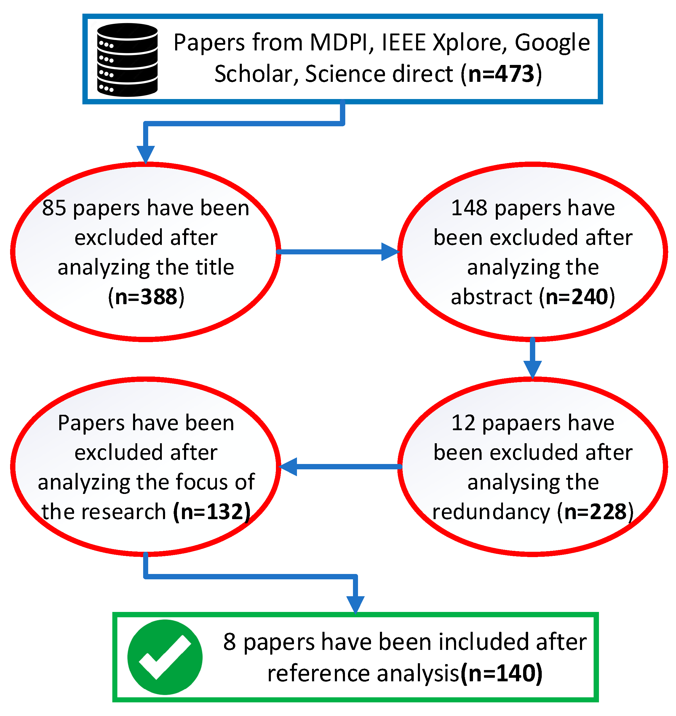
2. Literature Search Method
- Focused on sensor application
- Focused on path planning
- Focused on mapping techniques
- Focused on sensor fusion method adaptions
- Focused on machine learning adaptions
- Articles that are older than 5 years were excluded with some exceptions if specific points needed more investigation.
- Articles that do not focus on mobile robot navigation were excluded except if specific technology being investigated needed more input.
- Articles focusing on railways and sea navigation were not taken into consideration with the exception of several articles presenting air navigation systems.
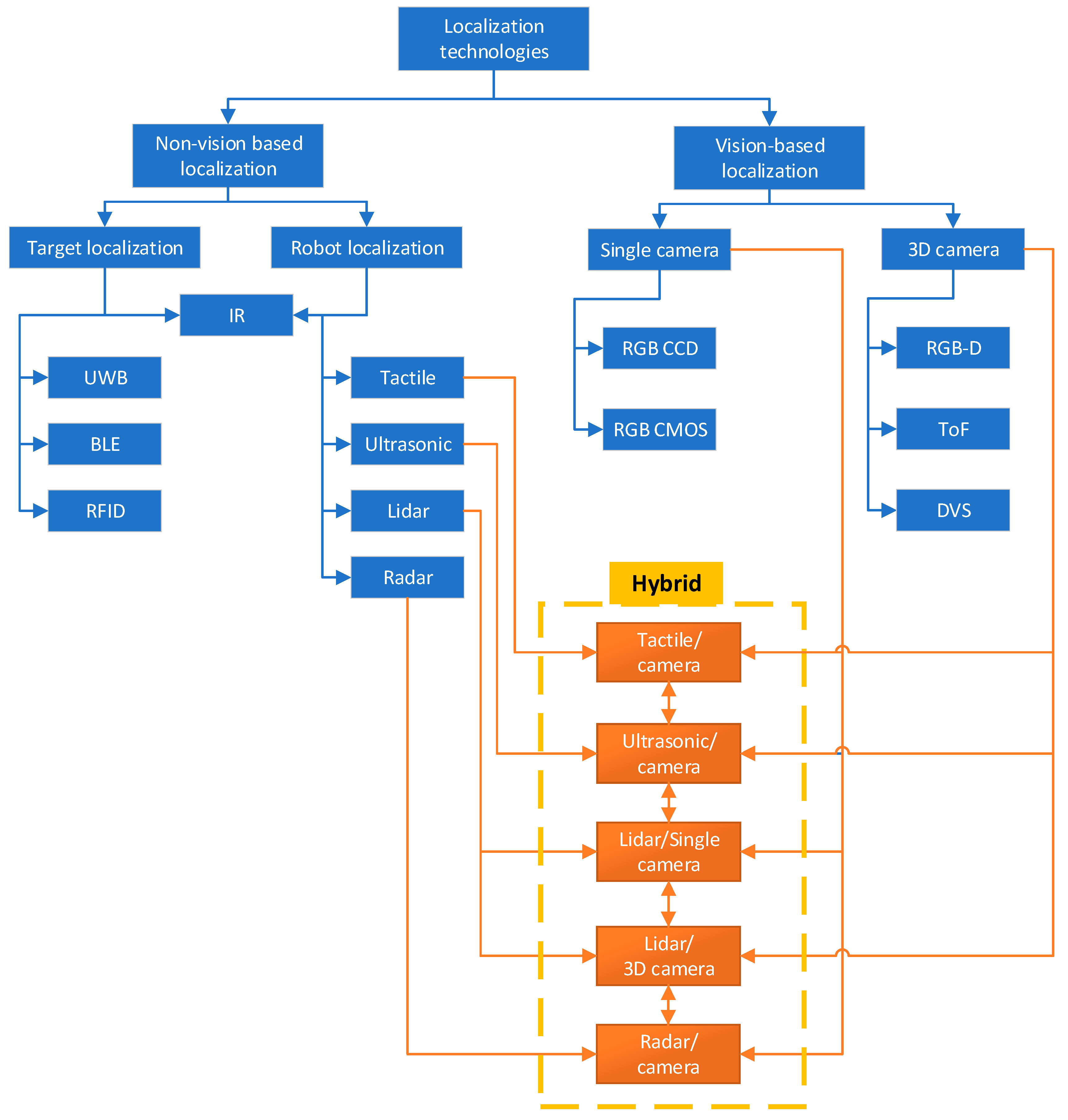
3. Navigation Methods
4. Analysis of Non-Vision-Based Localization Systems
5. Analysis of Vision-Based Localization Systems
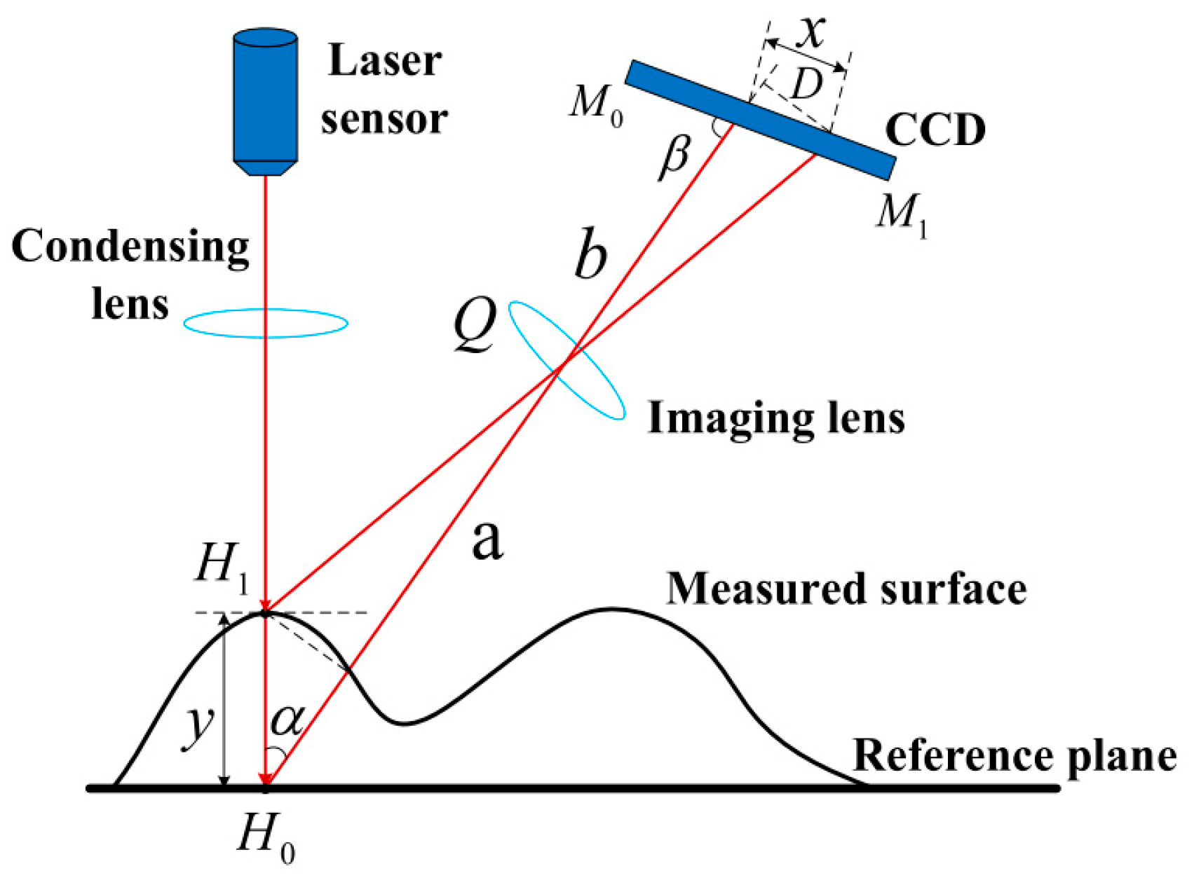
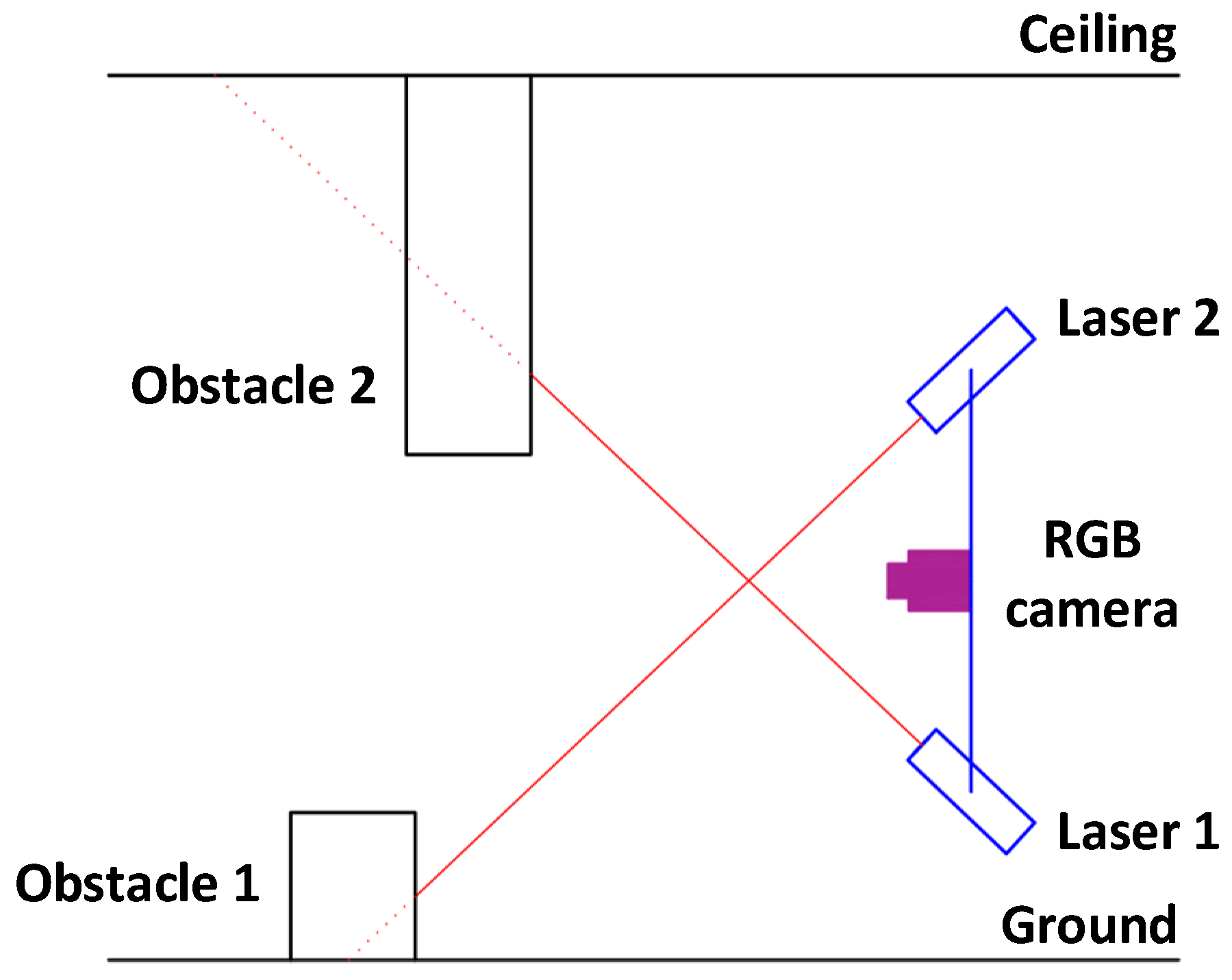
5.1. Standalone Vision Navigation Systems
5.2. Hybrid Visions Localization Systems
6. Essential Sensor Fusion Systems
- Low-level—indicates that raw sensor data are directly sent to fusion module. This way no data are lost because of noise introduced by postprocessing, meaning some relevant data would not be overlooked. For example, in article [102], LiDAR 3D point cloud points are augmented by semantically strong image features significantly increasing the number of detected 3D bounding boxes. Nevertheless, high computational resources are required to compute raw data. Also, fusion modules are less adaptive because adding new sensors requires adjustments to the new sensor format.
- Medium-level (Feature)—involves extracting some key features from raw sensors. Due to this, bandwidth is reduced before carrying data fusion and similar efficiency of extracting relevant data is achieved. Also, this structure is more adaptive and adjustable. This is a very commonly used fusion method, then optimization is important. For instance, in article [103], encoder, color image, and depth image are first pre-processed before fusion. Unnecessary noise is removed from images to filter only required regions, and encoder provides orientation, ultimately creating a system capable of object recognition and robot localization.
- High-level—according to this structure, each sensor is postprocessed and carries out its task independently, and then high-level fusion of detected objects or trajectories by each sensor is performed. This type of fusion has high modularity and simplicity. On the other hand, key sensor data at lower levels are lost.
- Complementary—sensor information does not directly depend on one another but then combined can provide a more complete picture of observed phenomena.
- Competitive (redundant)—same or similar information is received from sensors to reduce uncertainties and errors, which could appear if using sensors separately.
- Cooperative—involves combined information extraction that cannot be acquired using one sensor. Involves active sensor collaboration exchanging insight and or intermediate data and increasing accuracy and reliability of overall fusion system.
6.1. Sensor Fusion Using Kalman Filter
6.2. Sensor Fusion Using Particle Filter
6.3. Deep Learning for Sensor Fusion
7. Solution for Channel Robot Navigation System
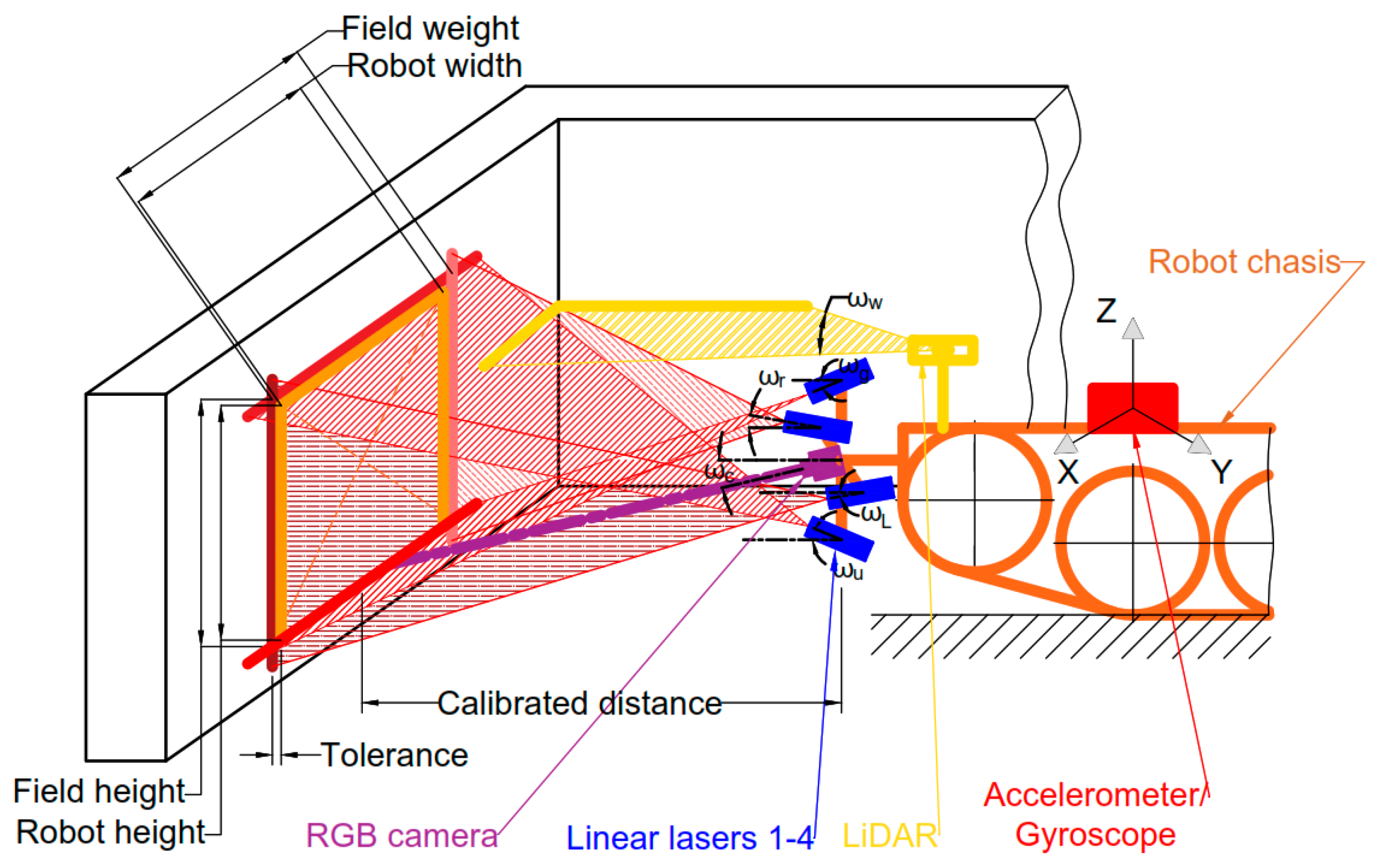
7.1. Obstacle Detection
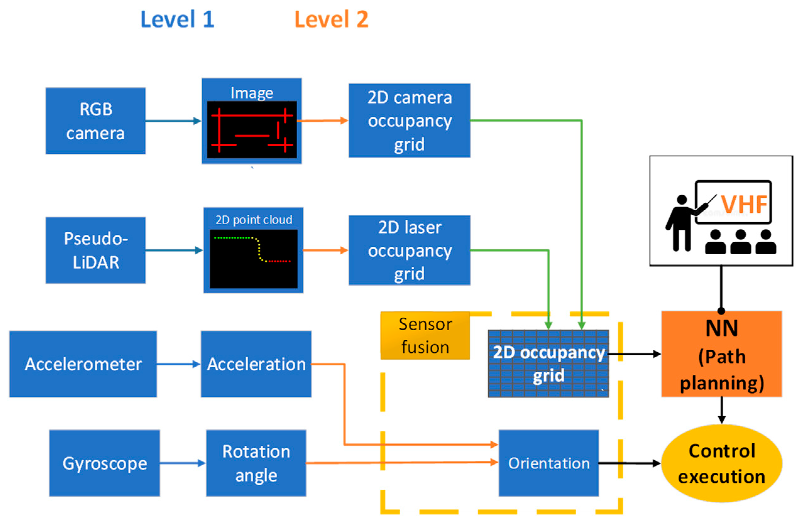
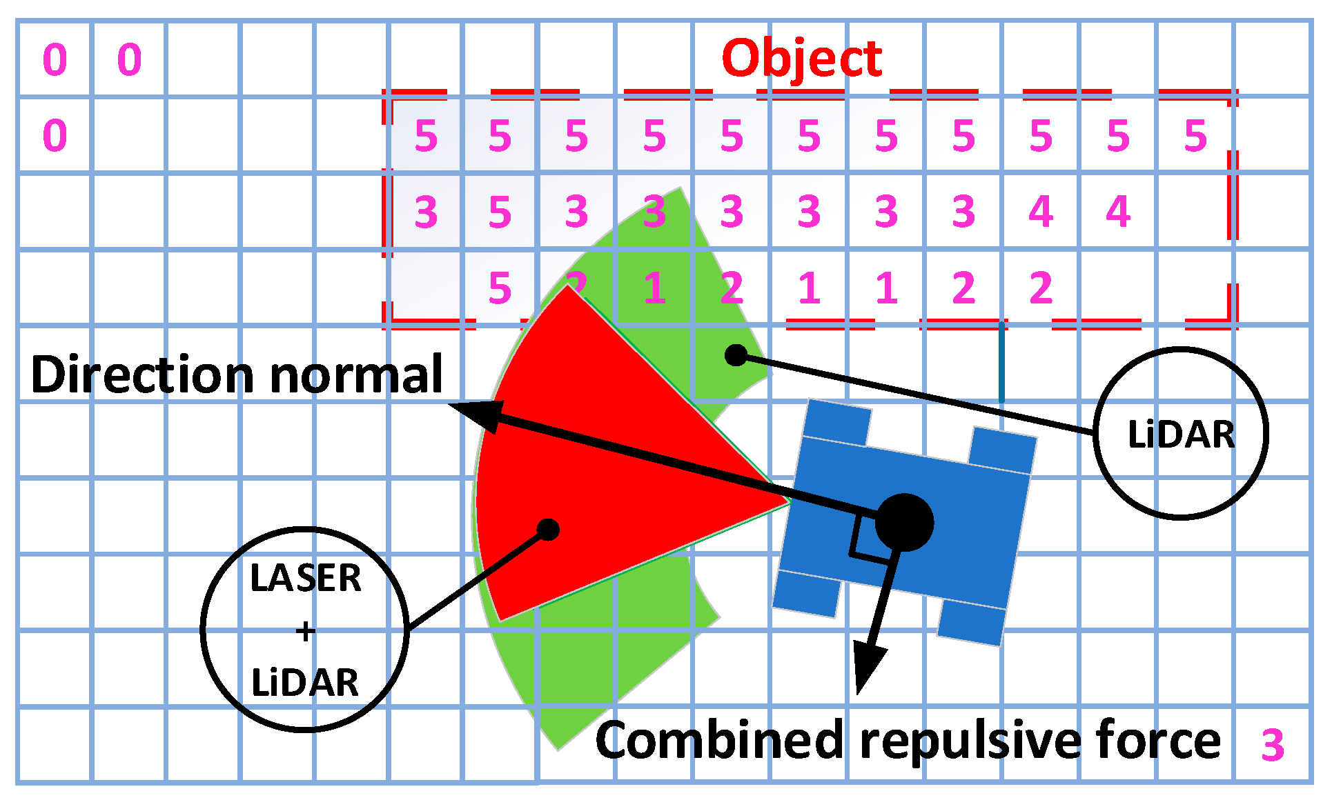
7.2. Sensor Fusion and Path Following Methodology
8. Discussion and Conclusions
Author Contributions
Funding
Data Availability Statement
Conflicts of Interest
References
- Sekaran, J.F.; Sugumari, T. A Review of Perception-Based Navigation System for Autonomous Mobile Robots. Recent Pat. Eng. 2022, 17, e290922209298. [Google Scholar] [CrossRef]
- Chen, J.; Wang, H.; Yang, S. Tightly Coupled LiDAR-Inertial Odometry and Mapping for Underground Environments. Sensors 2023, 23, 6834. [Google Scholar] [CrossRef]
- Tatsch, C.; Bredu, J.A.; Covell, D.; Tulu, I.B.; Gu, Y. Rhino: An Autonomous Robot for Mapping Underground Mine Environments. In Proceedings of the 2023 IEEE/ASME International Conference on Advanced Intelligent Mechatronics (AIM), Seattle, WA, USA, 28–30 June 2023; pp. 1166–1173. [Google Scholar] [CrossRef]
- Yang, L.; Li, P.; Qian, S.; Quan, H.; Miao, J.; Liu, M.; Hu, Y.; Memetimin, E. Path Planning Technique for Mobile Robots: A Review. Machines 2023, 11, 980. [Google Scholar] [CrossRef]
- Liu, Y.; Zhang, W.; Li, F.; Zuo, Z.; Huang, Q. Real-Time Lidar Odometry and Mapping with Loop Closure. Sensors 2022, 22, 4373. [Google Scholar] [CrossRef] [PubMed]
- Qin, H.; Shao, S.; Wang, T.; Yu, X.; Jiang, Y.; Cao, Z. Review of Autonomous Path Planning Algorithms for Mobile Robots. Drones 2023, 7, 211. [Google Scholar] [CrossRef]
- Jwo, D.J.; Biswal, A.; Mir, I.A. Artificial Neural Networks for Navigation Systems: A Review of Recent Research. Appl. Sci. 2023, 13, 4475. [Google Scholar] [CrossRef]
- Liu, C.; Lekkala, K.; Itti, L. World Model Based Sim2Real Transfer for Visual Navigation. arXiv 2023, arXiv:2310.18847. [Google Scholar]
- Almeida, J.; Rufino, J.; Alam, M.; Ferreira, J. A Survey on Fault Tolerance Techniques for Wireless Vehicular Networks. Electronics 2019, 8, 1358. [Google Scholar] [CrossRef]
- Alshammrei, S.; Boubaker, S.; Kolsi, L. Improved Dijkstra Algorithm for Mobile Robot Path Planning and Obstacle Avoidance. Comput. Mater. Contin. 2022, 72, 5939–5954. [Google Scholar] [CrossRef]
- Li, J.; Qin, H.; Wang, J.; Li, J. OpenStreetMap-Based Autonomous Navigation for the Four Wheel-Legged Robot Via 3D-Lidar and CCD Camera. IEEE Trans. Ind. Electron. 2022, 69, 2708–2717. [Google Scholar] [CrossRef]
- Martins, O.O.; Adekunle, A.A.; Olaniyan, O.M.; Bolaji, B.O. An Improved Multi-Objective a-Star Algorithm for Path Planning in a Large Workspace: Design, Implementation, and Evaluation. Sci. Afr. 2022, 15, e01068. [Google Scholar] [CrossRef]
- Wang, H.; Qi, X.; Lou, S.; Jing, J.; He, H.; Liu, W. An Efficient and Robust Improved A* Algorithm for Path Planning. Symmetry 2021, 13, 2213. [Google Scholar] [CrossRef]
- Abdulsaheb, J.A.; Kadhim, D.J. Classical and Heuristic Approaches for Mobile Robot Path Planning: A Survey. Robotics 2023, 12, 93. [Google Scholar] [CrossRef]
- Wang, H.; Fu, Z.; Zhou, J.; Fu, M.; Ruan, L. Cooperative Collision Avoidance for Unmanned Surface Vehicles Based on Improved Genetic Algorithm. Ocean Eng. 2021, 222, 108612. [Google Scholar] [CrossRef]
- Guo, N.; Li, C.; Wang, D.; Song, Y.; Liu, G.; Gao, T. Local Path Planning of Mobile Robot Based on Long Short-Term Memory Neural Network. Autom. Control Comput. Sci. 2021, 55, 53–65. [Google Scholar] [CrossRef]
- Zohaib, M.; Pasha, S.M.; Javaid, N.; Iqbal, J. IBA: Intelligent Bug Algorithm—A Novel Strategy to Navigate Mobile Robots Autonomously. Commun. Comput. Inf. Sci. 2013, 414, 291–299. [Google Scholar] [CrossRef]
- van Breda, R.; Smit, W.J. Applicability of Vector Field Histogram Star (Vfh*) on Multicopters. In Proceedings of the International Micro Air Vehicle Competition and Conference 2016, Beijing, China, 17–21 October 2016; pp. 62–69. [Google Scholar]
- Kobayashi, M.; Motoi, N. Local Path Planning: Dynamic Window Approach with Virtual Manipulators Considering Dynamic Obstacles. IEEE Access 2022, 10, 17018–17029. [Google Scholar] [CrossRef]
- Mishra, D.K.; Thomas, A.; Kuruvilla, J.; Kalyanasundaram, P.; Prasad, K.R.; Haldorai, A. Design of Mobile Robot Navigation Controller Using Neuro-Fuzzy Logic System. Comput. Electr. Eng. 2022, 101, 108044. [Google Scholar] [CrossRef]
- Durodié, Y.; Decoster, T.; Van Herbruggen, B.; Vanhie-Van Gerwen, J.; De Poorter, E.; Munteanu, A.; Vanderborght, B. A UWB-Ego-Motion Particle Filter for Indoor Pose Estimation of a Ground Robot Using a Moving Horizon Hypothesis. Sensors 2024, 24, 2164. [Google Scholar] [CrossRef]
- Wu, H.; Liu, H.; Roddelkopf, T.; Thurow, K. BLE Beacon-Based Floor Detection for Mobile Robots in a Multi-Floor Automation Laboratory. Transp. Saf. Environ. 2023, 6, tdad024. [Google Scholar] [CrossRef]
- Tripicchio, P.; D’Avella, S.; Unetti, M.; Motroni, A.; Nepa, P. A UHF Passive RFID Tag Position Estimation Approach Exploiting Mobile Robots: Phase-Only 3D Multilateration Particle Filters With No Unwrapping. IEEE Access 2024, 12, 58778–58788. [Google Scholar] [CrossRef]
- Özcan, M.; Aliew, F.; Görgün, H. Accurate and Precise Distance Estimation for Noisy IR Sensor Readings Contaminated by Outliers. Measurement 2020, 156, 107633. [Google Scholar] [CrossRef]
- Hu, H.; Zhang, C.; Pan, C.; Dai, H.; Sun, H.; Pan, Y.; Lai, X.; Lyu, C.; Tang, D.; Fu, J.; et al. Wireless Flexible Magnetic Tactile Sensor with Super-Resolution in Large-Areas. ACS Nano 2022, 16, 19271–19280. [Google Scholar] [CrossRef] [PubMed]
- Khaleel, H.Z.; Oleiwi, B.K. Ultrasonic Sensor Decision-Making Algorithm for Mobile Robot Motion in Maze Environment. Bull. Electr. Eng. Inform. 2024, 13, 109–116. [Google Scholar] [CrossRef]
- De Heuvel, J.; Zeng, X.; Shi, W.; Sethuraman, T.; Bennewitz, M. Spatiotemporal Attention Enhances Lidar-Based Robot Navigation in Dynamic Environments. IEEE Robot. Autom. Lett. 2024, 9, 4202–4209. [Google Scholar] [CrossRef]
- Cañadas-Aránega, F.; Blanco-Claraco, J.L.; Moreno, J.C.; Rodriguez-Diaz, F. Multimodal Mobile Robotic Dataset for a Typical Mediterranean Greenhouse: The GREENBOT Dataset. Sensors 2024, 24, 1874. [Google Scholar] [CrossRef] [PubMed]
- Brescia, W.; Gomes, P.; Toni, L.; Mascolo, S.; De Cicco, L. MilliNoise: A Millimeter-Wave Radar Sparse Point Cloud Dataset in Indoor Scenarios. In Proceedings of the MMSys ‘24: Proceedings of the 15th ACM Multimedia Systems Conference, Bari, Italy, 15–18 April 2024; pp. 422–428. [Google Scholar] [CrossRef]
- Ou, X.; You, Z.; He, X. Local Path Planner for Mobile Robot Considering Future Positions of Obstacles. Processes 2024, 12, 984. [Google Scholar] [CrossRef]
- Wang, C.; Zang, X.; Song, C.; Liu, Z.; Zhao, J.; Ang, M.H. Virtual Tactile POMDP-Based Path Planning for Object Localization and Grasping. Meas. J. Int. Meas. Confed. 2024, 230, 114480. [Google Scholar] [CrossRef]
- Armleder, S.; Dean-Leon, E.; Bergner, F.; Guadarrama Olvera, J.R.; Cheng, G. Tactile-Based Negotiation of Unknown Objects during Navigation in Unstructured Environments with Movable Obstacles. Adv. Intell. Syst. 2024, 6, 21. [Google Scholar] [CrossRef]
- Al-Mallah, M.; Ali, M.; Al-Khawaldeh, M. Obstacles Avoidance for Mobile Robot Using Type-2 Fuzzy Logic Controller. Robotics 2022, 11, 130. [Google Scholar] [CrossRef]
- Wondosen, A.; Shiferaw, D. Fuzzy Logic Controller Design for Mobile Robot Outdoor Navigation. arXiv 2017, arXiv:2401.01756. [Google Scholar]
- Sabra, M.; Tayeh, N. Maze Solver Robot. 2024. Available online: https://hdl.handle.net/20.500.11888/18671 (accessed on 15 December 2024).
- Kim, K.; Kim, J.; Jiang, X.; Kim, T. Static Force Measurement Using Piezoelectric Sensors. J. Sens. 2021, 2021, 6664200. [Google Scholar] [CrossRef]
- Kong, Y.; Cheng, G.; Zhang, M.; Zhao, Y.; Meng, W.; Tian, X.; Sun, B.; Yang, F.; Wei, D. Highly Efficient Recognition of Similar Objects Based on Ionic Robotic Tactile Sensors. Sci. Bull. 2024, 69, 2089–2098. [Google Scholar] [CrossRef]
- Zhang, S.; Yang, Y.; Sun, F.; Bao, L.; Shan, J.; Gao, Y.; Fang, B. A Compact Visuo-Tactile Robotic Skin for Micron-Level Tactile Perception. IEEE Sens. J. 2024, 24, 15273–15282. [Google Scholar] [CrossRef]
- Verellen, T.; Kerstens, R.; Steckel, J. High-Resolution Ultrasound Sensing for Robotics Using Dense Microphone Arrays. IEEE Access 2020, 8, 190083–190093. [Google Scholar] [CrossRef]
- Okuda, K.; Miyake, M.; Takai, H.; Tachibana, K. Obstacle Arrangement Detection Using Multichannel Ultrasonic Sonar for Indoor Mobile Robots. Artif. Life Robot. 2010, 15, 229–233. [Google Scholar] [CrossRef]
- Nair, S.; Joladarashi, S.; Ganesh, N. Evaluation of Ultrasonic Sensor in Robot Mapping. In Proceedings of the 2019 3rd International Conference on Trends in Electronics and Informatics (ICOEI), Tirunelveli, India, 23–25 April 2019. [Google Scholar]
- Li, Q.; Zhu, H. Performance Evaluation of 2D LiDAR SLAM Algorithms in Simulated Orchard Environments. Comput. Electron. Agric. 2024, 221, 108994. [Google Scholar] [CrossRef]
- Belkin, I.; Abramenko, A.; Yudin, D. Real-Time Lidar-Based Localization of Mobile Ground Robot. Procedia Comput. Sci. 2021, 186, 440–448. [Google Scholar] [CrossRef]
- Wang, H.; Yin, Y.; Jing, Q. Comparative Analysis of 3D LiDAR Scan-Matching Methods for State Estimation of Autonomous Surface Vessel. J. Mar. Sci. Eng. 2023, 11, 840. [Google Scholar] [CrossRef]
- Adams, M.; Jose, E.; Vo, B.-N. Robotic Navigation and Mapping with Radar; Artech: Morristown, NJ, USA, 2012; ISBN 9781608074839. [Google Scholar]
- Aucone, E.; Sferrazza, C.; Gregor, M.; D’Andrea, R.; Mintchev, S. Optical Tactile Sensing for Aerial Multi-Contact Interaction: Design, Integration, and Evaluation. IEEE Trans. Robot. 2024, 41, 364–377. [Google Scholar] [CrossRef]
- Omar, E.Z.; Al-Tahhan, F.E. A Novel Hybrid Model Based on Integrating RGB and YCrCb Color Spaces for Demodulating the Phase Map of Fibres Using a Color Phase-Shifting Profilometry Technique. Optik 2024, 306, 171792. [Google Scholar] [CrossRef]
- Maitlo, N.; Noonari, N.; Arshid, K.; Ahmed, N.; Duraisamy, S. AINS: Affordable Indoor Navigation Solution via Line Color Identification Using Mono-Camera for Autonomous Vehicles. In Proceedings of the IEEE 9th International Conference for Convergence in Technology (I2CT), Pune, India, 5–7 April 2024. [Google Scholar]
- Lan, H.; Zhang, E.; Jung, C. Face Reflection Removal Network Using Multispectral Fusion of RGB and NIR Images. IEEE Open J. Signal Process. 2024, 5, 383–392. [Google Scholar] [CrossRef]
- Zhang, Y.; Ma, Y.; Wu, Y.; Liu, L. Achieving Widely Distributed Feature Matches Using Flattened-Affine-SIFT Algorithm for Fisheye Images. Opt. Express 2024, 32, 7969. [Google Scholar] [CrossRef]
- Li, Y.; Moreau, J.; Ibanez-guzman, J. Emergent Visual Sensors for Autonomous Vehicles. IEEE Trans. Intell. Transp. Syst. 2023, 24, 4716–4737. [Google Scholar] [CrossRef]
- Tychola, K.A.; Tsimperidis, I.; Papakostas, G.A. On 3D Reconstruction Using RGB-D Cameras. Digital 2022, 2, 401–421. [Google Scholar] [CrossRef]
- Varghese, G.; Reddy, T.G.C.; Menon, A.K.; Paul, A.; Kochuvila, S.; Varma Divya, R.; Bhat, R.; Kumar, N. Multi-Robot System for Mapping and Localization. In Proceedings of the 2023 8th International Conference on Robotics and Automation Engineering (ICRAE), Singapore, 17–19 November 2023; pp. 79–84. [Google Scholar] [CrossRef]
- Ghosh, D.K.; Jung, Y.J. Two-Stage Cross-Fusion Network for Stereo Event-Based Depth Estimation. Expert Syst. Appl. 2024, 241, 122743. [Google Scholar] [CrossRef]
- Kim, T.; Lim, S.; Shin, G.; Sim, G.; Yun, D. An Open-Source Low-Cost Mobile Robot System with an RGB-D Camera and Efficient Real-Time Navigation Algorithm. IEEE Access 2022, 10, 127871–127881. [Google Scholar] [CrossRef]
- Canovas, B.; Nègre, A.; Rombaut, M. Onboard Dynamic RGB-D Simultaneous Localization and Mapping for Mobile Robot Navigation. ETRI J. 2021, 43, 617–629. [Google Scholar] [CrossRef]
- Abukhalil, T.; Alksasbeh, M.; Alqaralleh, B.; Abukaraki, A. Robot Navigation System Using Laser and a Monocular Camera. J. Theor. Appl. Inf. Technol. 2020, 98, 714–724. [Google Scholar]
- Tsujimura, T.; Minato, Y.; Izumi, K. Shape Recognition of Laser Beam Trace for Human-Robot Interface. Pattern Recognit. Lett. 2013, 34, 1928–1935. [Google Scholar] [CrossRef]
- Romero-Godoy, D.; Sánchez-Rodríguez, D.; Alonso-González, I.; Delgado-Rajó, F. A Low Cost Collision Avoidance System Based on a ToF Camera for SLAM Approaches. Rev. Tecnol. Marcha 2022, 35, 137–144. [Google Scholar] [CrossRef]
- Iaboni, C.; Lobo, D.; Choi, J.W.; Abichandani, P. Event-Based Motion Capture System for Online Multi-Quadrotor Localization and Tracking. Sensors 2022, 22, 3240. [Google Scholar] [CrossRef]
- Jiang, P.; Ergu, D.; Liu, F.; Cai, Y.; Ma, B. A Review of Yolo Algorithm Developments. Procedia Comput. Sci. 2021, 199, 1066–1073. [Google Scholar] [CrossRef]
- Zhang, J.; Zhang, Y.; Liu, J.; Lan, Y.; Zhang, T. Human Figure Detection in Han Portrait Stone Images via Enhanced YOLO-V5. Herit. Sci. 2024, 12, 119. [Google Scholar] [CrossRef]
- Plastiras, G.; Kyrkou, C.; Theocharides, T. Efficient Convnet-Based Object Detection for Unmanned Aerial Vehicles by Selective Tile Processing. In Proceedings of the ICDSC ‘18: Proceedings of the 12th International Conference on Distributed Smart Cameras, Eindhoven, The Netherlands, 3–4 September 2018. [Google Scholar] [CrossRef]
- Hussain, M. YOLOv1 to v8: Unveiling Each Variant-A Comprehensive Review of YOLO. IEEE Access 2024, 12, 42816–42833. [Google Scholar] [CrossRef]
- Verma, T.; Singh, J.; Bhartari, Y.; Jarwal, R.; Singh, S.; Singh, S. SOAR: Advancements in Small Body Object Detection for Aerial Imagery Using State Space Models and Programmable Gradients. arXiv 2024, arXiv:2405.01699. [Google Scholar]
- Minz, P.S.; Saini, C.S. RGB Camera-Based Image Technique for Color Measurement of Flavored Milk. Meas. Food 2021, 4, 100012. [Google Scholar] [CrossRef]
- Sohl, M.A.; Mahmood, S.A. Low-Cost UAV in Photogrammetric Engineering and Remote Sensing: Georeferencing, DEM Accuracy, and Geospatial Analysis. J. Geovisualization Spat. Anal. 2024, 8, 14. [Google Scholar] [CrossRef]
- Haruta, M.; Kikkawa, J.; Kimoto, K.; Kurata, H. Comparison of Detection Limits of Direct-Counting CMOS and CCD Cameras in EELS Experiments. Ultramicroscopy 2022, 240, 113577. [Google Scholar] [CrossRef] [PubMed]
- Ünal, Z.; Kızıldeniz, T.; Özden, M.; Aktaş, H.; Karagöz, Ö. Detection of Bruises on Red Apples Using Deep Learning Models. Sci. Hortic. 2024, 329, 113021. [Google Scholar] [CrossRef]
- Furmonas, J.; Liobe, J.; Barzdenas, V. Analytical Review of Event-Based Camera Depth Estimation Methods and Systems. Sensors 2022, 22, 1201. [Google Scholar] [CrossRef]
- Hidalgo-Carrio, J.; Gehrig, D.; Scaramuzza, D. Learning Monocular Dense Depth from Events. In Proceedings of the 2020 International Conference on 3D Vision (3DV), Fukuoka, Japan, 25–28 November 2020; pp. 534–542. [Google Scholar] [CrossRef]
- Fan, L.; Li, Y.; Jiang, C.; Wu, Y. Unsupervised Depth Completion and Denoising for RGB-D Sensors. In Proceedings of the 2022 International Conference on Robotics and Automation (ICRA), Philadelphia, PA, USA, 23–27 May 2022; pp. 8734–8740. [Google Scholar] [CrossRef]
- Miranda, J.C.; Arnó, J.; Gené-Mola, J.; Lordan, J.; Asín, L.; Gregorio, E. Assessing Automatic Data Processing Algorithms for RGB-D Cameras to Predict Fruit Size and Weight in Apples. Comput. Electron. Agric. 2023, 214, 108302. [Google Scholar] [CrossRef]
- Guo, S.; Yoon, S.C.; Li, L.; Wang, W.; Zhuang, H.; Wei, C.; Liu, Y.; Li, Y. Recognition and Positioning of Fresh Tea Buds Using YOLOv4-Lighted + ICBAM Model and RGB-D Sensing. Agriculture 2023, 13, 518. [Google Scholar] [CrossRef]
- Osvaldová, K.; Gajdošech, L.; Kocur, V.; Madaras, M. Enhancement of 3D Camera Synthetic Training Data with Noise Models. arXiv 2024, arXiv:2402.16514. [Google Scholar]
- Hou, C.; Qiao, T.; Dong, H.; Wu, H. Coal Flow Volume Detection Method for Conveyor Belt Based on TOF Vision. Meas. J. Int. Meas. Confed. 2024, 229, 114468. [Google Scholar] [CrossRef]
- Horaud, R.; Hansard, M.; Evangelidis, G.; Ménier, C. An Overview of Depth Cameras and Range Scanners Based on Time-of-Flight Technologies. Mach. Vis. Appl. 2016, 27, 1005–1020. [Google Scholar] [CrossRef]
- Condotta, I.C.F.S.; Brown-Brandl, T.M.; Pitla, S.K.; Stinn, J.P.; Silva-Miranda, K.O. Evaluation of Low-Cost Depth Cameras for Agricultural Applications. Biol. Syst. Eng. 2020, 173, 105394. [Google Scholar] [CrossRef]
- Zhu, X.-F.; Xu, T.; Wu, X.-J. Adaptive Colour-Depth Aware Attention for RGB-D Object Tracking. IEEE Signal Process. Lett. 2024; early access. [Google Scholar] [CrossRef]
- Mac, T.T.; Lin, C.Y.; Huan, N.G.; Nhat, L.D.; Hoang, P.C.; Hai, H.H. Hybrid Slam-Based Exploration of a Mobile Robot for 3d Scenario Reconstruction and Autonomous Navigation. Acta Polytech. Hung. 2021, 18, 197–212. [Google Scholar] [CrossRef]
- Gomez-Rosal, D.A.; Bergau, M.; Fischer, G.K.J.; Wachaja, A.; Grater, J.; Odenweller, M.; Piechottka, U.; Hoeflinger, F.; Gosala, N.; Wetzel, N.; et al. A Smart Robotic System for Industrial Plant Supervision. In Proceedings of the 2023 IEEE SENSORS, Vienna, Austria, 29 October–1 November 2023; pp. 1–13. [Google Scholar] [CrossRef]
- Huang, X.; Dong, X.; Ma, J.; Liu, K.; Ahmed, S.; Lin, J.; Qiu, B. The Improved A* Obstacle Avoidance Algorithm for the Plant Protection UAV with Millimeter Wave Radar and Monocular Camera Data Fusion. Remote Sens. 2021, 13, 3364. [Google Scholar] [CrossRef]
- Chaki, N.; Devarakonda, N.; Cortesi, A.; Seetha, H. Proceedings of International Conference on Computational Intelligence and Data Engineering: ICCIDE 2021 (Lecture Notes on Data Engineering and Communications Technologies); Springer: Berlin/Heidelberg, Germany, 2021; ISBN 9789811671814. [Google Scholar]
- Saucedo, M.A.V.; Patel, A.; Sawlekar, R.; Saradagi, A.; Kanellakis, C.; Agha-Mohammadi, A.A.; Nikolakopoulos, G. Event Camera and LiDAR Based Human Tracking for Adverse Lighting Conditions in Subterranean Environments. IFAC-PapersOnLine 2023, 56, 9257–9262. [Google Scholar] [CrossRef]
- Le, N.M.D.; Nguyen, N.H.; Nguyen, D.A.; Ngo, T.D.; Ho, V.A. ViART: Vision-Based Soft Tactile Sensing for Autonomous Robotic Vehicles. IEEE/ASME Trans. Mechatron. 2023, 29, 1420–1430. [Google Scholar] [CrossRef]
- Cai, Y.; Ou, Y.; Qin, T. Improving SLAM Techniques with Integrated Multi-Sensor Fusion for 3D Reconstruction. Sensors 2024, 24, 2033. [Google Scholar] [CrossRef] [PubMed]
- Lang, X.; Li, L.; Zhang, H.; Xiong, F.; Xu, M.; Liu, Y.; Zuo, X.; Lv, J. Gaussian-LIC: Photo-Realistic LiDAR-Inertial-Camera SLAM with 3D Gaussian Splatting. arXiv 2024, arXiv:2404.06926. [Google Scholar]
- Bhattacharjee, T.; Shenoi, A.A.; Park, D.; Rehg, J.M.; Kemp, C.C. Combining Tactile Sensing and Vision for Rapid Haptic Mapping. In Proceedings of the 2015 IEEE/RSJ International Conference on Intelligent Robots and Systems (IROS), Hamburg, Germany, 28 September–2 October 2015; pp. 1200–1207. [Google Scholar] [CrossRef]
- Álvarez, D.; Roa, M.A.; Moreno, L. Visual and Tactile Fusion for Estimating the Pose of a Grasped Object. Adv. Intell. Syst. Comput. 2020, 1093 AISC, 184–198. [Google Scholar] [CrossRef]
- Naga, P.S.B.; Hari, P.J.; Sinduja, R.; Prathap, S.; Ganesan, M. Realization of SLAM and Object Detection Using Ultrasonic Sensor and RGB-HD Camera. In Proceedings of the 2022 International Conference on Wireless Communications Signal Processing and Networking (WiSPNET), Chennai, India, 24–26 March 2022; pp. 167–171. [Google Scholar]
- Chen, X.; Wang, S.; Zhang, B.; Luo, L. Multi-Feature Fusion Tree Trunk Detection and Orchard Mobile Robot Localization Using Camera/Ultrasonic Sensors. Comput. Electron. Agric. 2018, 147, 91–108. [Google Scholar] [CrossRef]
- Lin, Z.; Gao, Z.; Chen, B.M.; Chen, J.; Li, C. Accurate LiDAR-Camera Fused Odometry and RGB-Colored Mapping. IEEE Robot. Autom. Lett. 2024, 9, 2495–2502. [Google Scholar] [CrossRef]
- You, H.; Xu, F.; Ye, Y.; Xia, P.; Du, J. Adaptive LiDAR Scanning Based on RGB Information. Autom. Constr. 2024, 160, 105337. [Google Scholar] [CrossRef]
- Jing, J. Simulation Analysis of Fire-Fighting Path Planning Based On SLAM. Highlights Sci. Eng. Technol. 2024, 85, 434–442. [Google Scholar] [CrossRef]
- Tan, C.J.; Ogawa, S.; Hayashi, T.; Janthori, T.; Tominaga, A.; Hayashi, E. 3D Semantic Mapping Based on RGB-D Camera and LiDAR Sensor in Beach Environment. In Proceedings of the 2024 1st International Conference on Robotics, Engineering, Science, and Technology (RESTCON), Pattaya, Thailand, 16–18 February 2024; pp. 21–26. [Google Scholar]
- Qiao, G.; Ning, N.; Zuo, Y.; Zhou, P.; Sun, M.; Hu, S.; Yu, Q.; Liu, Y. Spatio-Temporal Fusion Spiking Neural Network for Frame-Based and Event-Based Camera Sensor Fusion. IEEE Trans. Emerg. Top. Comput. Intell. 2024, 8, 2446–2456. [Google Scholar] [CrossRef]
- Zuo, Y.F.; Xu, W.; Wang, X.; Wang, Y.; Kneip, L. Cross-Modal Semidense 6-DOF Tracking of an Event Camera in Challenging Conditions. IEEE Trans. Robot. 2024, 40, 1600–1616. [Google Scholar] [CrossRef]
- Yadav, R.; Vierling, A.; Berns, K. Radar+RGB Attentive Fusion for Robust Object Detection in Autonomous Vehicles. arXiv 2020, arXiv:2008.13642. [Google Scholar]
- Yao, S.; Guan, R.; Huang, X.; Li, Z.; Sha, X.; Yue, Y.; Lim, E.G.; Seo, H.; Man, K.L.; Zhu, X.; et al. Radar-Camera Fusion for Object Detection and Semantic Segmentation in Autonomous Driving: A Comprehensive Review. IEEE Trans. Intell. Veh. 2024, 9, 2094–2128. [Google Scholar] [CrossRef]
- Aeberhard, M.; Kaempchen, N. High-Level Sensor Data Fusion Architecture for Vehicle Surround Environment Perception. 2015. Available online: https://www.researchgate.net/publication/267725657 (accessed on 10 December 2024).
- Thakur, A.; Mishra, S.K. An In-Depth Evaluation of Deep Learning-Enabled Adaptive Approaches for Detecting Obstacles Using Sensor-Fused Data in Autonomous Vehicles. Eng. Appl. Artif. Intell. 2024, 133, 108550. [Google Scholar] [CrossRef]
- Rövid, A.; Remeli, V.; Szalay, Z. Raw Fusion of Camera and Sparse LiDAR for Detecting Distant Objects Fusion von Kameradaten Und Spärlichem LiDAR-Rohsignal Zur Erkennung Entfernter Objekte. At-Automatisierungstechnik 2020, 68, 337–346. [Google Scholar] [CrossRef]
- Li, F.; Li, W.; Chen, W.; Xu, W.; Huang, L.; Li, D.; Cai, S.; Yang, M.; Xiong, X.; Liu, Y. A Mobile Robot Visual SLAM System with Enhanced Semantics Segmentation. IEEE Access 2020, 8, 25442–25458. [Google Scholar] [CrossRef]
- Hassani, S.; Dackermann, U.; Mousavi, M.; Li, J. A Systematic Review of Data Fusion Techniques for Optimized Structural Health Monitoring. Inf. Fusion 2024, 103, 102136. [Google Scholar] [CrossRef]
- Thakur, A.; Pachamuthu, R. LiDAR and Camera Raw Data Sensor Fusion in Real-Time for Obstacle Detection. In Proceedings of the 2023 IEEE Sensors Applications Symposium (SAS), Ottawa, ON, Canada, 18–20 July 2023. [Google Scholar]
- Risti, D.; Gao, G.; Leu, A. Low-Level Sensor Fusion-Based Human Tracking. Ristić-Durrant 2016, 15, 17–32. [Google Scholar]
- Puriyanto, R.D.; Mustofa, A.K.; Dahlan, U.A.; Author, C. Design and Implementation of Fuzzy Logic for Obstacle Avoidance in Differential Drive Mobile Robot. J. Robot. Control. JRC 2024, 5, 132–141. [Google Scholar] [CrossRef]
- Kim, T.; Member, S.; Kang, G.; Member, S. Development of an Indoor Delivery Mobile Robot for a Multi-Floor Environment. IEEE Access 2024, 12, 45202–45215. [Google Scholar] [CrossRef]
- Azhar, G.A.; Kusuma, A.C.; Izza, S. Differential Drive Mobile Robot Motion Accuracy Improvement with Odometry-Compass Sensor Fusion Implementation. ELKHA 2023, 15, 24–31. [Google Scholar]
- Li, J.; Liu, Y.; Wang, S.; Wang, L.; Sun, Y.; Li, X. Visual Perception System Design for Rock Breaking Robot Based on Multi-Sensor Fusion. Multimed. Tools Appl. 2024, 83, 24795–24814. [Google Scholar] [CrossRef]
- Park, G. Optimal Vehicle Position Estimation Using Adaptive Unscented Kalman Filter Based on Sensor Fusion. Mechatronics 2024, 99, 103144. [Google Scholar] [CrossRef]
- Jiang, P.; Hu, C.; Wang, T.; Lv, K.; Guo, T.; Jiang, J.; Hu, W. Research on a Visual/Ultra-Wideband Tightly Coupled Fusion Localization Algorithm. Sensors 2024, 24, 1710. [Google Scholar] [CrossRef]
- Hu, K.; Chen, Z.; Kang, H.; Tang, Y. 3D Vision Technologies for a Self-Developed Structural External Crack Damage Recognition Robot. Autom. Constr. 2024, 159, 105262. [Google Scholar] [CrossRef]
- Sarmento, J.; Neves dos Santos, F.; Silva Aguiar, A.; Filipe, V.; Valente, A. Fusion of Time-of-Flight Based Sensors with Monocular Cameras for a Robotic Person Follower. J. Intell. Robot. Syst. Theory Appl. 2024, 110, 30. [Google Scholar] [CrossRef]
- Zheng, X.; Ji, S.; Pan, Y.; Zhang, K.; Wu, C. NeurlT: Pushing the Limit of Neural Inertial Tracking for Indoor Robotic IoT. arXiv 2024, arXiv:2404.08939. [Google Scholar]
- Li, C.; Chen, K.; Li, H.; Luo, H. Engineering Applications of Artificial Intelligence Multisensor Data Fusion Approach for Sediment Assessment of Sewers in Operation. Eng. Appl. Artif. Intell. 2024, 132, 107965. [Google Scholar] [CrossRef]
- Gao, H.; Li, X.; Song, X. A Fusion Strategy for Vehicle Positioning at Intersections Utilizing UWB and Onboard Sensors. Sensors 2024, 24, 476. [Google Scholar] [CrossRef] [PubMed]
- Ming, Z.; Berrio, J.S.; Shan, M.; Worrall, S. OccFusion: A Straightforward and Effective Multi-Sensor Fusion Framework for 3D Occupancy Prediction. arXiv 2024, arXiv:2403.01644v3. [Google Scholar]
- Kocic, J.; Jovicic, N.; Drndarevic, V. Sensors and Sensor Fusion in Autonomous Vehicles. In Proceedings of the 2018 26th Telecommunications Forum (TELFOR), Belgrade, Serbia, 20–21 November 2018. [Google Scholar] [CrossRef]
- Luo, R.C.; Chang, N.W.; Lin, S.C.; Wu, S.C. Human Tracking and Following Using Sensor Fusion Approach for Mobile Assistive Companion Robot. In Proceedings of the 2009 35th Annual Conference of IEEE Industrial Electronics, Porto, Portugal, 3–5 November 2009; pp. 2235–2240. [Google Scholar] [CrossRef]
- Khodarahmi, M.; Maihami, V. A Review on Kalman Filter Models. Arch. Comput. Methods Eng. 2023, 30, 727–747. [Google Scholar] [CrossRef]
- Arpitha Shankar, S.I.; Shivakumar, M. Sensor Fusion Based Multiple Robot Navigation in an Indoor Environment. Int. J. Interact. Des. Manuf. 2024, 18, 4841–4852. [Google Scholar] [CrossRef]
- Yara, R.; Konstantinos, T.; Roland, H.; John, C.; Eleni, C.; Markus, R. Unscented Kalman Filter–Based Fusion of GNSS, Accelerometer, and Rotation Sensors for Motion Tracking. J. Struct. Eng. 2024, 150, 5024002. [Google Scholar] [CrossRef]
- Nguyen, T.; Mann, G.K.I.; Vardy, A.; Gosine, R.G. CKF-Based Visual Inertial Odometry for Long-Term Trajectory Operations. J. Robot. 2020, 2020, 7362952. [Google Scholar] [CrossRef]
- Liu, C.; Li, H.; Wang, Z. FastTrack: A Highly Efficient and Generic GPU-Based Multi-Object Tracking Method with Parallel Kalman Filter. Int. J. Comput. Vis. 2023, 132, 1463–1483. [Google Scholar] [CrossRef]
- Damsgaard, B.; Gaasdal, S.S.; Bonnerup, S. Multi-Sensor Fusion with Radar and Ultrasound for Obstacle Avoidance on Capra Hircus 1.0. In Proceedings of the 11th Student Symposium on Mechanical and Manufacturing Engineering, Parit Raja, Malaysia, 25–26 August 2021; pp. 1–8. [Google Scholar]
- Cai, Y.; Qin, T.; Ou, Y.; Wei, R. Intelligent Systems in Motion: A Comprehensive Review on Multi-Sensor Fusion and Information Processing From Sensing to Navigation in Path Planning. Int. J. Semant. Web Inf. Syst. 2023, 19, 1–35. [Google Scholar] [CrossRef]
- Jamil, H.; Jian, Y. An Evolutionary Enhanced Particle Filter-Based Fusion Localization Scheme for Fast Tracking of Smartphone Users in Tall Complex Buildings for Hazardous Situations. IEEE Sens. J. 2024, 24, 6799–6812. [Google Scholar] [CrossRef]
- Tang, Q.; Liang, J.; Zhu, F. A Comparative Review on Multi-Modal Sensors Fusion Based on Deep Learning. Signal Process. 2023, 213, 109165. [Google Scholar] [CrossRef]
- Thepsit, T.; Konghuayrob, P.; Saenthon, A.; Yanyong, S. Localization for Outdoor Mobile Robot Using LiDAR and RTK-GNSS/INS. Sensors Mater. 2024, 36, 1405–1418. [Google Scholar] [CrossRef]
- Jiang, H.; Lu, Y.; Zhang, D.; Shi, Y.; Wang, J. Deep Learning-Based Fusion Networks with High-Order Attention Mechanism for 3D Object Detection in Autonomous Driving Scenarios. Appl. Soft Comput. 2024, 152, 111253. [Google Scholar] [CrossRef]
- Fu, G.; Menciassi, A.; Dario, P. Development of a Low-Cost Active 3D Triangulation Laser Scanner for Indoor Navigation of Miniature Mobile Robots. Rob. Auton. Syst. 2012, 60, 1317–1326. [Google Scholar] [CrossRef]
- KlanÄnik, S.; BaliÄ, J.; PlaninšiÄ, P. Obstacle Detection with Active Laser Triangulation. Adv. Prod. Eng. Manag. 2007, 2, 79–90. [Google Scholar]
- França, J.G.D.M.; Gazziro, M.A.; Ide, A.N.; Saito, J.H. A 3D Scanning System Based on Laser Triangulation and Variable Field of View. In Proceedings of the IEEE International Conference on Image Processing 2005, Genova, Italy, 14 September 2005; Volume 1, pp. 425–428. [Google Scholar] [CrossRef]
- Fu, G.; Corradi, P.; Menciassi, A.; Dario, P. An Integrated Triangulation Laser Scanner for Obstacle Detection of Miniature Mobile Robots in Indoor Environment. IEEE/ASME Trans. Mechatron. 2011, 16, 778–783. [Google Scholar] [CrossRef]
- Schlarp, J.; Csencsics, E.; Schitter, G. Design and Evaluation of an Integrated Scanning Laser Triangulation Sensor. Mechatronics 2020, 72, 102453. [Google Scholar] [CrossRef]
- Ding, D.; Ding, W.; Huang, R.; Fu, Y.; Xu, F. Research Progress of Laser Triangulation On-Machine Measurement Technology for Complex Surface: A Review. Meas. J. Int. Meas. Confed. 2023, 216, 113001. [Google Scholar] [CrossRef]
- So, E.W.Y.; Munaro, M.; Michieletto, S.; Antonello, M.; Menegatti, E. Real-Time 3D Model Reconstruction with a Dual-Laser Triangulation System for Assembly Line Completeness Inspection. Adv. Intell. Syst. Comput. 2013, 194 AISC, 707–716. [Google Scholar] [CrossRef]
- Dong, H.; Weng, C.Y.; Guo, C.; Yu, H.; Chen, I.M. Real-Time Avoidance Strategy of Dynamic Obstacles via Half Model-Free Detection and Tracking with 2D Lidar for Mobile Robots. IEEE/ASME Trans. Mechatron. 2021, 26, 2215–2225. [Google Scholar] [CrossRef]
- Gul, F.; Rahiman, W.; Nazli Alhady, S.S. A Comprehensive Study for Robot Navigation Techniques. Cogent Eng. 2019, 6, 1632046. [Google Scholar] [CrossRef]


| Navigation G(Global), L(Local) | Method | Working Principle | Ref. |
|---|---|---|---|
| G | Dijkstra | Shortest path planning between established nodes | [10,11] |
| G | A star (A*) | Graphical search for shortest path to destination node | [12,13] |
| G | Artificial protentional field (APF) | Defined obstacles generate artificial repulsive force which in sum with attractive target force creates a path | [14] |
| G | Genetic algorithm | Heuristic methods that use mutation principle for optimal path generation from defined scenarios | [15] |
| G | Neural network (NN) | Learning algorithm that can be trained with known trajectory inputs and outputs to generate a path. | [16] |
| L | Bug | Moves in straight line to the target until obstacle is detected and evaded moving from one obstacle to another | [17] |
| L | Vector field histogram (VHF) | Occupancy grid is generated using sensor data, and target artificial force is attracting the robot while discrete obstacle data are pushing the robot; thus obstacles are evaded | [18] |
| L | Dynamic window | Sensor field of view is discretized in separate windows, which react to obstacles and maneuver to the target avoiding them | [19] |
| L | Fuzzy logic | Rule based method which can work with imprecise data using fuzzy values | [20] |
| Sensor | Methodology | Path Planning Method | Advantages | Disadvantages | Ref. |
|---|---|---|---|---|---|
| LiDAR | 2D LiDAR data are transformed in polar coordinates and clustering is performed using Euclidean algorithm | Improved time elastic band (TEB) method for local obstacle avoidance | System is able accurately react to dynamic obstacles, also by evaluating dynamic obstacle velocities, they can be evaded faster | Very dependent on localization algorithm accuracy | [30] |
| Tactile | Tactile sensors are used for target localization with robot hand setup | Path planning is realized using novel Virtual Tactile POMDP (VT-POMDP)-based method dedicated for partially observable domains | Allows to mimic human touch for object localization | Localization is not solved for scenarios with additional objects and obstacles | [31] |
| Using tactile sensors, robot is able to react to obstacles and adjust trajectory to the goal | For global planning trajectory to the goal is estimated with A* algorithm | System is able to react not only to stationary but also to dynamic obstacles. | Field of view is low for obstacle detection, thus trajectory optimization is low. Contact is required for obstacle detection. | [32] | |
| IR | Three coordinated IR distance sensors estimating distance to an obstacle. | Type 2 Fuzzy controller for local path planning | Good dynamic response and accuracy of the system | Very close objects cannot be detected also field of view is narrow | [33] |
| Ultrasonic | Ultrasonic sensors mounted on four sides of the robot for obstacle detection | Fuzzy controller is used for local path planning | Effective robot localization in simple maps | Not effective in very narrow spaces also influenced by sensors | [34] |
| Radar | A point cloud dataset called Milli noise captured with radar in indoor navigation scenarios | Dijkstra global path planning methods were used | Accurate point-wise labeling can be provided | High computational resources | [29] |
| Criteria/ Method | Operating Distance | Field of View | Accuracy | Sensitivity to Disturbance | Computational Resources | Implementation Cost | Ref. |
|---|---|---|---|---|---|---|---|
| IR | 10–400 cm | 20–60° | 2 mm | Moderate | Moderate | Moderate | [24,35] |
| Tactile | Contact | N/A | Up to 1% | Moderate | Low | Low | [36,37,38] |
| Ultrasonic | 2 cm–10 m | 15–30° | 1–3 cm | Very high | Moderate | Low | [39,40,41] |
| Lidar | 0.1–100 m | 0–360° (3D, 2D) | 1–3 cm (3D), <1 cm (2D) | High | Very High | High | [42,43,44] |
| Radar | 1–300 m | 120–360° | 1–10 cm | Low | High | High | [45] |
| Sensor | Methodology | Path Planning Method | Advantages | Disadvantages | Ref. |
|---|---|---|---|---|---|
| RGB-D | Travers ability map is extracted from raw depth images using tiny-YOLOv3 to endure safe driving for low-body mobile robots | A* with fast marching method for faster distance cost calculation | Low-cost system enabling obstacle detection and path planning in real-time | Refresh rate is relatively slow for avoiding dynamically moving pedestrians | [55] |
| RGB-D | Closed-loop real-time dense RGB-D SLAM algorithm incorporating tiny-YOLOv4, which reconstructs dense 3D background for indoor mobile robot navigation | Optimal optimalRRT planner, which accelerates computation of faltered robot-centric point cloud for path planning | Provides faster computation of path planning in real time compared to conventional SLAM methods | Accuracy is affected by surface color, varying distance to the static, and dynamic objects | [56] |
| RGB | Pattern recognition using two laser pointers to detect and avoid obstacles using LaGrange interpolation formula to determine the distance | Rotation angle of the robot is adjusted according to the calculated distance of two laser pointers | Lower computation load and cost-efficient mobile robot navigation system | Influenced by light in a way that observed view does not have enough color contrast, also influenced by camera proximity | [57] |
| RGB | RGB CCD camera takes an image recognizing the red color shape drawn with laser pointer calculating velocity vector | Mobile robot performs steering tasks according to drawn shapes | Cost-efficient vision system enables to detect laser pointer trajectory | Precision of shape detection is affected by surface color and reflectivity | [58] |
| ToF | ToF camera is used for indoor obstacle detection where GPS signal is weaker then outside | Global path planning and local obstacle avoidance | Cost-efficient system for obstacle detection that is relatively accurate with different lighting of surfaces | In complex scenes, light can deflect multiple times, causing calculation problems | [59] |
| DVS | Multi-quadrotor localization and tracking is performed using event-based camera and deep learning network based on YOLOv5 and k-dimensional tree | MINLP-based motion planner, which enables quadrotor to calculate its position velocity and distance to other obstacles and quadrotors | Relatively cost-efficient system that is able to perform localization and path planning of multi-quadrotor systems | Limited field of view when object is close to camera, requires sufficient training data | [60] |
| Criteria/ Method | Range | Color | Depth Accuracy | Sensitivity to Disturbance | Computational Resources | Implementation Cost | Ref. |
|---|---|---|---|---|---|---|---|
| RGB CCD | N/A | ✔ | N/A | High | Low | Moderate | [66,67] |
| RGB CMOS | N/A | ✔ | N/A | Very high | Low | Low | [68,69] |
| DVS | 0.6–30 m | ✔ | 61–98% | Low | Very high | Very high | [70,71] |
| RGB-D | 0.5–10 m | ✔ | Up to 97% | High | High | High | [72,73,74] |
| ToF | 0.35–10 m | N/A | Up to 99% | Moderate | Moderate | Moderate | [75,76,77] |
| Sensor | Methodology | Path Planning Method | Advantages | Disadvantages | Ref. |
|---|---|---|---|---|---|
| 2D LiDAR, RGB-D | Visual-based SLAM and laser-based Slam is used incorporating EKF based LiDAR and RGB-D fusion for environment mapping and robot localization | RRT* (Rapidly exploring random tree) global path planning and Fuzzy PID controller for following trajectory accurately | Integration of visual input provides richer data especially when LiDAR has a lack of data in wide areas | Additional visual maps increase computational load significantly | [80] |
| 2D LiDAR RGB | Reinforced learning method uses visual data acquired with CenterNet depicting obstacles and projects these data in birds-eye view using LiDAR point cloud | While A* is implemented for global path planning, timed elastic bands (TEB) are implemented locally, complemented by reinforced learning | More accurate representation of distant and close objects using sensor fusion | High computational load, requires training data for image recognition and localization tasks | [81] |
| Radar, RGB | Visual data are inspected using Canny edge and then spatial fusion is used for camera and MMV radar to obtain data about the same target | Improved A* global method is used adding dynamic heuristic function for dynamic adjustment of cost between two points | Significantly improved object recognition and distance estimation for more accurate obstacle avoidance | Camera and radar require calibration for accurate data fusion result also sensitive to the distance to an object | [82] |
| Ultrasonic, RGB CMOS | YOLOv3 based on CNN is used to detect obstacles with camera, and fusion with ultrasonic sensor is used for distance estimation | Tested capability of obstacle detection for local navigations tasks | Allows to estimate distance to an object recognized by camera in real time | Accuracy of 90% for distance estimation, and recognition is relatively low | [83] |
| 3D Lidar, DVS | Event camera compares changes in intensity for detection and acquired data is fused with point cloud by pairing clusters | Nonlinear Model Predictive Control (NMPC) is used for human tracking | Human detection is effective in high contrast zones | High computational resources | [84] |
| IR, Tactile, RGB | Fisheye camera to detect IR markers on soft skin structure is respective coordinate systems to detect tactile changes | Robot has three defined conditions including move towards the goal, move backward, and move along the object, which are controlled with PI controller | Highly accurate tactile data enabling to navigate in very narrow spaces | Complex calibration is required, friction with obstacles influences navigation accuracy | [85] |
| Criteria/ Method | Range | Field of View | Accuracy | Sensitivity to Disturbance | Computational Resources | Implementation Cost | Ref. |
|---|---|---|---|---|---|---|---|
| Tactile/ RGB-D | 0.5–10 m | 60–180° | Up to 1% | Moderate | Moderate | Moderate | [88,89] |
| Ultrasonic/ RGB | 2 cm–10 m | 60–180° | 1–3 cm | High | Moderate | Low | [90,91] |
| Lidar/RGB | 0.1–100 m | 360° (3D, 2D) | 1–3 cm (3D), <1 cm (2D) | Very high | High | High | [92,93] |
| Lidar/ RGB-D | 0.1–100 m | 360° (3D, 2D) | 1–3 cm (3D), <1 cm (2D) | High | Very high | Very high | [94,95] |
| Lidar/ DVS | 0.1–100 m | 360° (3D, 2D) | 1–3 cm (3D), <1 cm (2D) | Low | Very high | Very high | [96,97] |
| Radar/RGB | 1–300 m | 120–360° | 1–10 cm | Moderate | High | Moderate | [98,99] |
| Sensor | Methodology | Advantages | Disadvantages | Ref. |
|---|---|---|---|---|
| LiDAR, Camera | The point cloud generated using LiDAR is projected onto the image in real time. Point cloud is projected by colors referencing depth information | Accurate representation of the environment in real time for autonomous vehicle | High computational resources. Raw data has to be projected at a very high rate, faster than the acquisition rate | [105] |
| Stereo camera, LRF | Fusion-based human detection and tracking algorithm combining laser data-based search window and Kalman filter for recursive estimation of target position in robots coordinate system | Able to detect and track fast human movements in real time | High computational resources | [106] |
| Sensor | Methodology | Advantages | Disadvantages | Ref. |
|---|---|---|---|---|
| Encoder, ultrasonic | Fuzzy logic algorithm input is acquired from ultrasonic sensors for obstacle detection and the motion is executed with feedback from wheel encoders | Fats and cost-efficient obstacle avoidance system | Slippage can introduce motion execution inaccuracies | [107] |
| 3D LiDAR, GMSL camera | YOLACT image semantic segmentation algorithm for obstacle detection is used and then LiDAR point cloud is matched with the shape corresponding to camera pixels | Semantic segmentation algorithm allows for more accurate obstacle detection evaluating its shape | 3D LiDAR requires high computational resources because of large point cloud | [108] |
| Encoder, compass | Odometry data are obtained based on wheels and encoders data and then fused with compass data using extended Kalman filter providing data for further movement to the target | Increased position accuracy to not more than 0.15 m | Inaccurate data are common because of wheel slippage, which cannot be evaluated by selected sensors | [109] |
| LiDAR, RGB camera | LiDAR and Camera joint calibration is initiated with spatial relationship, then target detection is initiated using deep learning PP-YOLOv2 and identification of surface using point cloud segmentation based on RANSAC. | Allows accurate detection of objects with suitable surfaces required for processing. Segmentation accuracy of 75.46%. | Suitable only for calibrated type of processed material. If material type changes, tuning is required. | [110] |
| IMU, LiDAR, RGB camera | A dense 3D map is obtained in real time using simultaneous localization and mapping (SLAM) while IMU sensors track short-term motion. Using reinforced learning RL and CNN algorithms obstacles are avoided mapping image and LiDAR data | Enables fully autonomous system allowing not only object recognition but also identification of various environmental factors | High computational resources. Requires training and large number of labeled data for ML algorithms | [81] |
| Global positioning system (GPS), IMU | GPS and IMU sensor data are interconnected using adaptive covariance matrix and adaptive unscented Kalman filter (AUKF) for vehicle position estimation | Outputs robust and accurate vehicle position estimation. AUKF yields better results than UKF or EKF filters | System is still affected by environment obstructions like buildings and depends on accurate kinematic model | [111] |
| Ultra-wideband (UWB), RGB-D | Kalman filter is used to reduce noise of UWB data, which are then fused with localization data acquired from image data processed with ORB-SLAM2. EKF is used for ORB-SLAM2/UWB fusion. | Significantly improves positioning accuracy compared to standalone UWB systems | Positioning accuracy strongly depends on field size because of UWB range limitations | [112] |
| 3D LiDAR, RGB-D | For data fusion, first LiDAR and cameras are calibrated using edges for relative orientation parameters. Canny edge is used for extracting color image features. RANSAC is used for point cloud depth mapping. Extrinsic matrix is used for projecting point cloud onto an image. | Able to identify and locate cracks and evaluate geometric size with accuracy not more than 0.1mm using MobileNetV2-DeepLabV3 | High computational resources for generating dense 3D point cloud and image semantic segmentation. | [113] |
| UWB, monocular camera | Histogram filter (RHF) is used for sensor fusion, which can handle exponential and Gaussian systems. Range information of UWB is fused with angle estimations received from the camera | 66.67% reduction in angular error is achieved compared to standalone UWB systems | Positioning accuracy strongly depends on field size and anchor infrastructure because of UWB range limitations. | [114] |
| Gyroscope, accelerometer, magnetometer | Neural inertial tracking system (NeurIT) is incorporated, which incorporates RNN and transformers | Enables accurate indoor tracking, minimizing the drift appearing from extended periods or distances | System is only suitable for tracking | [115] |
| Sensor | Methodology | Advantages | Disadvantages | Ref. |
|---|---|---|---|---|
| Gyroscope, accelerometer, odometer, sonar | Unscented Kalman filter and Rauch–Tung–Striebel are applied to fuse raw Gyroscope, accelerometer, and odometer data for precise localization of the robot, then sonar point cloud is fused with sensor data for offset adjustment and environment calculations | Accurate robot localization and orientation acquisition. | 3D environment representation. Sonar-based measurement introduces noise in closed environments. | [116] |
| UWB, encoder, speed sensor, accelerometer, GBSS, gyroscope | UWB and vehicle on board sensor fusion, which consisted of three components including multi sensor module, ARIMA-GARCH for UWB data processing, and global fusion module using AIMM and extended Kalman filter | Increases positioning accuracy in GNSS-challenging environments | Additional infrastructure for UWB is required, readability of communications must be ensured. | [117] |
| LiDAR, Camera, Radar | Image data are extracted using ResNet101-DCN, then dense 3D point cloud and sparse 3D point cloud are generated using VoxelNet, and then the postprocessed data of all sensors are merged using BEVFusion and SENet | Accurate and robust occupancy prediction of working environment even with challenging night and rainy scenarios | High computational resources for generating dense 3D point cloud | [118] |
Disclaimer/Publisher’s Note: The statements, opinions and data contained in all publications are solely those of the individual author(s) and contributor(s) and not of MDPI and/or the editor(s). MDPI and/or the editor(s) disclaim responsibility for any injury to people or property resulting from any ideas, methods, instructions or products referred to in the content. |
© 2025 by the authors. Licensee MDPI, Basel, Switzerland. This article is an open access article distributed under the terms and conditions of the Creative Commons Attribution (CC BY) license (https://creativecommons.org/licenses/by/4.0/).
Share and Cite
Ušinskis, V.; Nowicki, M.; Dzedzickis, A.; Bučinskas, V. Sensor-Fusion Based Navigation for Autonomous Mobile Robot. Sensors 2025, 25, 1248. https://doi.org/10.3390/s25041248
Ušinskis V, Nowicki M, Dzedzickis A, Bučinskas V. Sensor-Fusion Based Navigation for Autonomous Mobile Robot. Sensors. 2025; 25(4):1248. https://doi.org/10.3390/s25041248
Chicago/Turabian StyleUšinskis, Vygantas, Michał Nowicki, Andrius Dzedzickis, and Vytautas Bučinskas. 2025. "Sensor-Fusion Based Navigation for Autonomous Mobile Robot" Sensors 25, no. 4: 1248. https://doi.org/10.3390/s25041248
APA StyleUšinskis, V., Nowicki, M., Dzedzickis, A., & Bučinskas, V. (2025). Sensor-Fusion Based Navigation for Autonomous Mobile Robot. Sensors, 25(4), 1248. https://doi.org/10.3390/s25041248