
Autocollimation-Based Roll Angle Sensor Using a Modified Right-Angle Prism for Large Range Measurements

Abstract
1. Introduction
2. Methodology
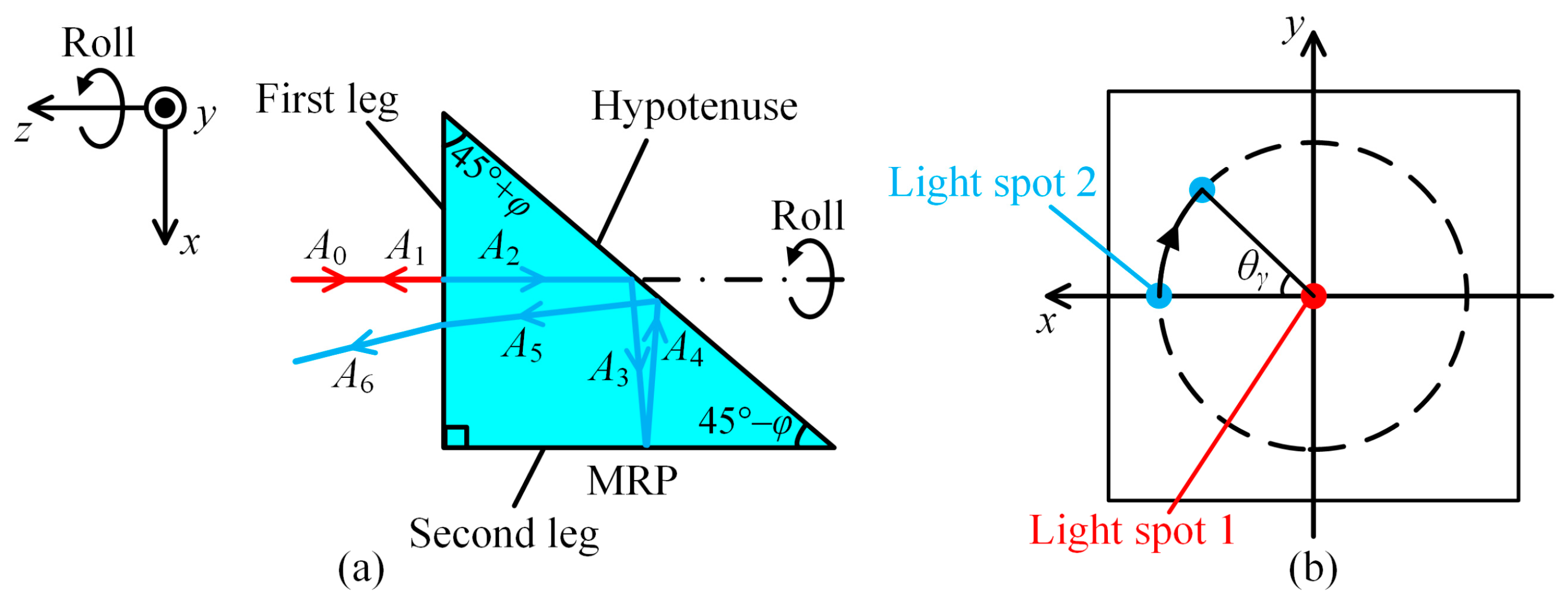
2.1. Optical System
2.2. Measuring Roll Angle
2.3. Crosstalk Effect
3. Experimental Results
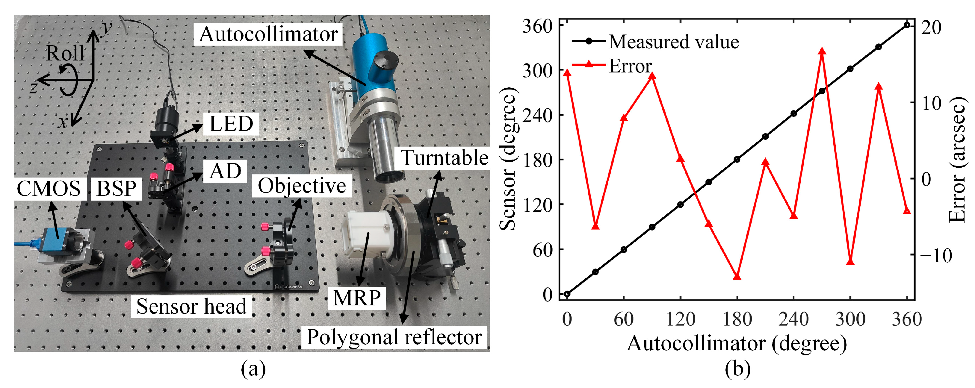
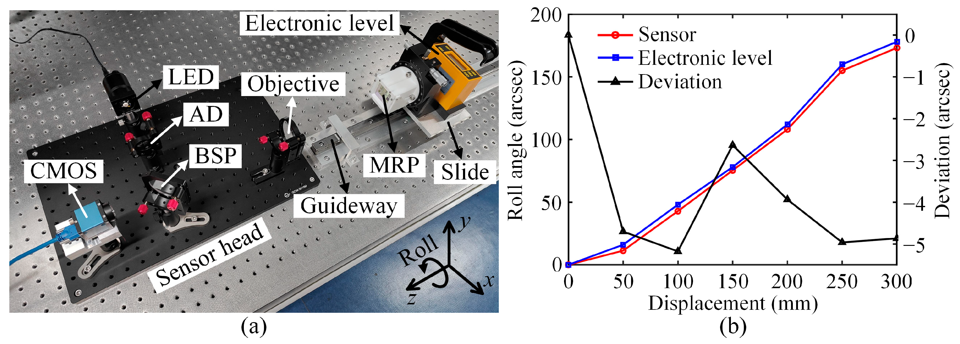
3.1. Experimental Apparatus
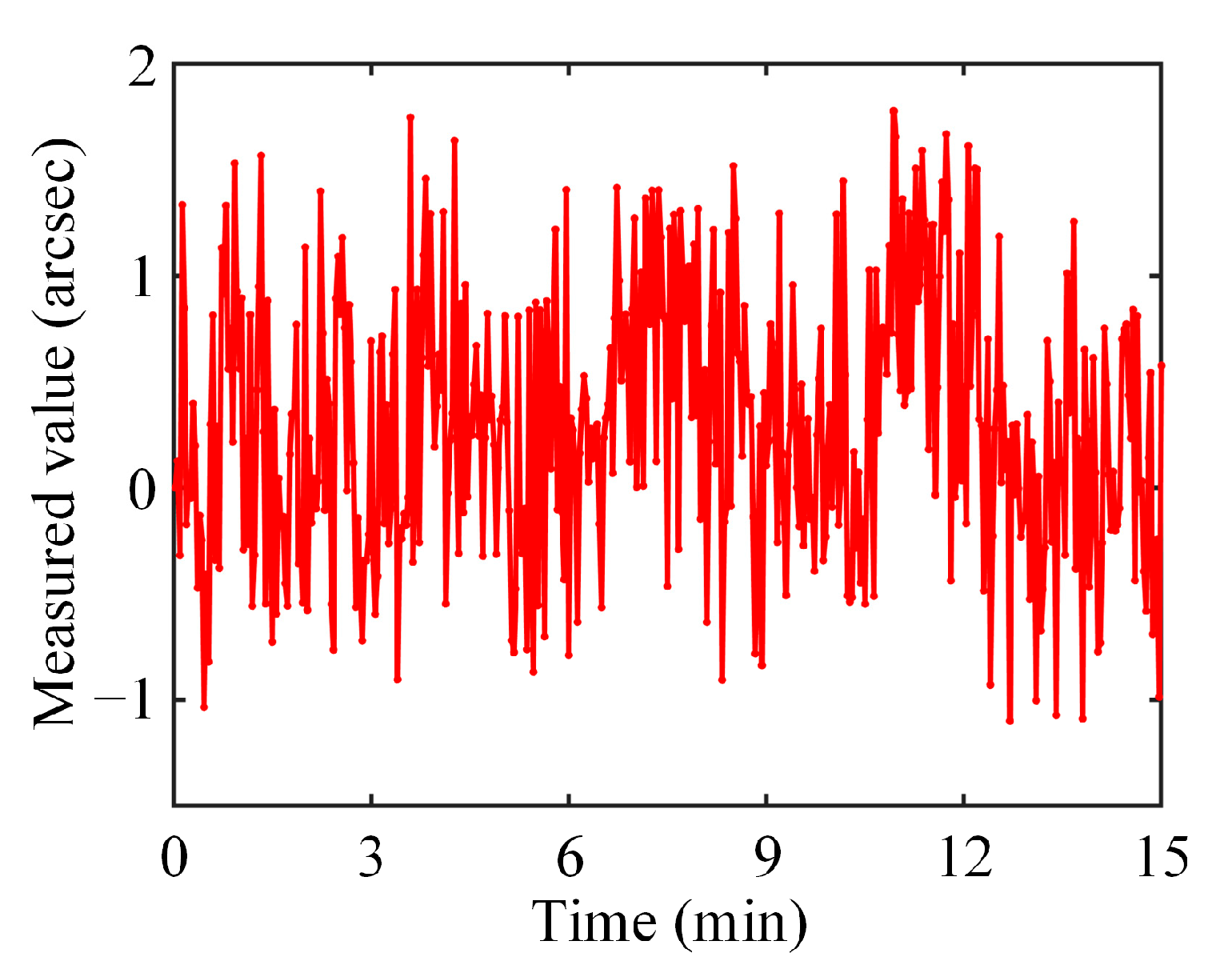
3.2. Stability and Repeatability Tests
3.3. Roll Angle Calibration
3.4. Comparison and Resolution Tests
4. Conclusions and Discussion
Author Contributions
Funding
Institutional Review Board Statement
Informed Consent Statement
Data Availability Statement
Conflicts of Interest
References
- Konyakhin, I.A.; Turgalieva, T.V. Autocollimating systems for roll angle measurement of large-scale object deformation. Proc. SPIE 2015, 9525, 952543. [Google Scholar]
- Gao, Y.; Wang, X.; Huang, Z.; Zhan, D.; Hu, C. High-precision rolling angle measurement for a three-dimensional collimator. Appl. Opt. 2014, 53, 6629–6634. [Google Scholar] [CrossRef] [PubMed]
- Zhang, P.; Gao, M.; Wang, W.; Wang, Y.; Su, X.; Che, J. A novel method for measuring roll angle. Meas. Sci. Technol. 2024, 35, 086104. [Google Scholar] [CrossRef]
- Deng, Z.; Shen, Q.; Deng, Z.; Cheng, J. Real-time estimation for roll angle of spinning projectile based on phase-locked loop on signals from single-axis magnetometer. Sensors 2019, 19, 839. [Google Scholar] [CrossRef] [PubMed]
- Shimizu, Y.; Kataoka, S.; Gao, W. High resolution clinometers for measurement of roll error motion of a precision linear slide. Chin. J. Mech. Eng. 2018, 31, 92. [Google Scholar] [CrossRef]
- Fan, K.C.; Wang, T.H.; Lin, S.Y.; Liu, Y.C. Design of a dual-axis optoelectronic level for precision angle measurements. Meas. Sci. Technol. 2011, 22, 055302. [Google Scholar] [CrossRef]
- Lee, C.; Lee, S. Multi-degree-of-freedom motion error measurement in an ultraprecision machine using laser encoder—Review. J. Mech. Sci. Technol. 2013, 27, 141–152. [Google Scholar] [CrossRef]
- Wang, S.; Ma, R.; Cao, F.; Luo, L.; Li, X. A review: High-precision angle measurement technologies. Sensors 2024, 24, 1755. [Google Scholar] [CrossRef]
- Shimizu, Y.; Matsukuma, H.; Gao, W. Optical sensors for multi-axis angle and displacement measurement using grating reflectors. Sensors 2019, 19, 5289. [Google Scholar] [CrossRef]
- Zhang, P.; Wang, Y.; Kuang, C.; Li, S.; Liu, X. Measuring roll angle displacement based on ellipticity with high resolution and large range. Opt. Laser Technol. 2015, 65, 126–130. [Google Scholar] [CrossRef]
- Zhai, Y.; Feng, Q.; Zhang, B. A simple roll measurement method based on a rectangular-prism. Opt. Laser Technol. 2012, 44, 839–843. [Google Scholar] [CrossRef]
- Cai, Y.; Yang, B.; Fan, K. Robust roll angular error measurement system for precision machines. Opt. Express 2019, 27, 8027–8036. [Google Scholar] [CrossRef] [PubMed]
- Lee, J.; Sung, W.; Hsu, C. Dynamic range enhancement of the roll angle displacement measurement with birefringence using a polarization camera. Appl. Opt. 2021, 60, 9110–9116. [Google Scholar] [CrossRef] [PubMed]
- Kumar, Y.P.; Chatterjee, S.; Negi, S.S. Small roll angle measurement using lateral shearing cyclic path polarization interferometry. Appl. Opt. 2016, 55, 979–983. [Google Scholar] [CrossRef] [PubMed]
- Hsieh, H.L.; Pan, S.W. Development of a grating-based interferometer for six-degree-of-freedom displacement and angle measurements. Opt. Express 2015, 23, 2451–2465. [Google Scholar] [CrossRef]
- Liu, X.; Wang, Y.; Zhu, L.; Wang, B.; Yan, P. High-precision dynamic measurement of roll angle based on digital holography. Opt. Lasers Eng. 2023, 169, 107711. [Google Scholar] [CrossRef]
- Kim, J.A.; Kim, K.C.; Bae, E.W.; Kim, S.; Kwak, Y.K. Six-degree-of-freedom displacement measurement system using a diffraction grating. Rev. Sci. Instrum. 2000, 71, 3214–3219. [Google Scholar] [CrossRef]
- Kim, J.A.; Bae, E.W.; Kim, S.H.; Kwak, Y.K. Design methods for six-degree-of-freedom displacement measurement systems using cooperative targets. Precis. Eng. 2002, 26, 99–104. [Google Scholar] [CrossRef]
- Gao, W.; Saito, Y.; Muto, H.; Arai, Y.; Shimizu, Y. A three-axis autocollimator for detection of angular error motions of a precision stage. CIRP Ann. 2011, 60, 515–518. [Google Scholar] [CrossRef]
- Ren, W.; Cui, J.; Tan, J. Precision roll angle measurement system based on autocollimation. Appl. Opt. 2022, 61, 3811–3818. [Google Scholar] [CrossRef]
- Ren, W.; Cui, J.; Tan, J. A three-dimensional small angle measurement system based on autocollimation method. Rev. Sci. Instrum. 2022, 93, 055102. [Google Scholar] [CrossRef] [PubMed]
- Li, R.; Xie, L.; Zhen, Y.; Xiao, H.; Wang, W.; Guo, J.; Konyakhin, I.; Nikitin, M.; Yu, X. Roll angle autocollimator measurement method based on a cylindrical cube-corner reflector with a high resolution and large range. Opt. Express 2022, 30, 7147–7161. [Google Scholar] [CrossRef] [PubMed]
- Guo, Y.; Cheng, H.; Wen, Y.; Feng, Y. Three-degree-of-freedom autocollimator based on a combined target reflector. Appl. Opt. 2020, 59, 2262–2269. [Google Scholar] [CrossRef] [PubMed]


Disclaimer/Publisher’s Note: The statements, opinions and data contained in all publications are solely those of the individual author(s) and contributor(s) and not of MDPI and/or the editor(s). MDPI and/or the editor(s) disclaim responsibility for any injury to people or property resulting from any ideas, methods, instructions or products referred to in the content. |
© 2025 by the authors. Licensee MDPI, Basel, Switzerland. This article is an open access article distributed under the terms and conditions of the Creative Commons Attribution (CC BY) license (https://creativecommons.org/licenses/by/4.0/).
Share and Cite
Guo, Y.; Zhang, Y.; Ji, J.; Di, H.; Yan, Q.; Wang, L.; Hua, D. Autocollimation-Based Roll Angle Sensor Using a Modified Right-Angle Prism for Large Range Measurements. Sensors 2025, 25, 1250. https://doi.org/10.3390/s25041250
Guo Y, Zhang Y, Ji J, Di H, Yan Q, Wang L, Hua D. Autocollimation-Based Roll Angle Sensor Using a Modified Right-Angle Prism for Large Range Measurements. Sensors. 2025; 25(4):1250. https://doi.org/10.3390/s25041250
Chicago/Turabian StyleGuo, Yan, Yu Zhang, Jiali Ji, Huige Di, Qing Yan, Li Wang, and Dengxin Hua. 2025. "Autocollimation-Based Roll Angle Sensor Using a Modified Right-Angle Prism for Large Range Measurements" Sensors 25, no. 4: 1250. https://doi.org/10.3390/s25041250
APA StyleGuo, Y., Zhang, Y., Ji, J., Di, H., Yan, Q., Wang, L., & Hua, D. (2025). Autocollimation-Based Roll Angle Sensor Using a Modified Right-Angle Prism for Large Range Measurements. Sensors, 25(4), 1250. https://doi.org/10.3390/s25041250