
An Equivalent Magnetic-Circuit-Modeling Approach for Analysis of Conical Permanent Magnet Synchronous Motor

Abstract
1. Introduction
- Axial Electromagnetic Force Interference: Structural inevitability of residual axial electromagnetic forces adversely affects thrust precision while introducing parasitic axial vibration sources.
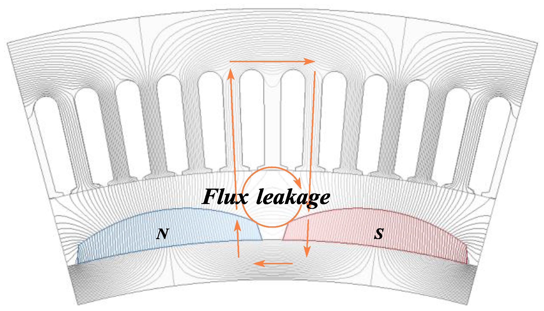
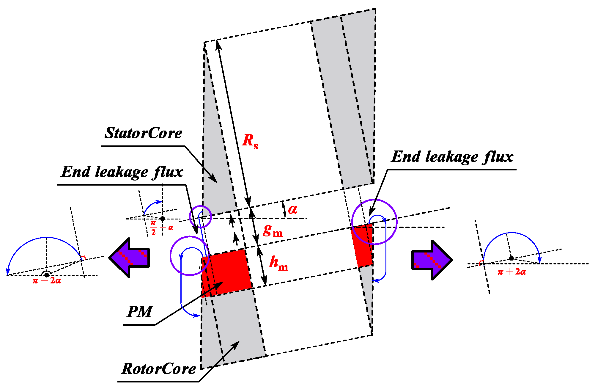
- End Leakage Flux Limitations: Geometric constraints of conical topology exacerbate magnetic flux leakage at extremities, constraining peak thrust output capability.
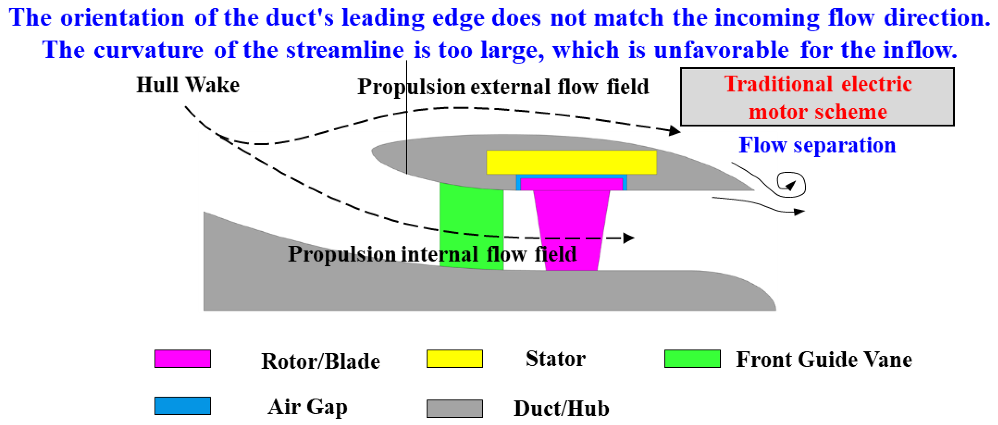
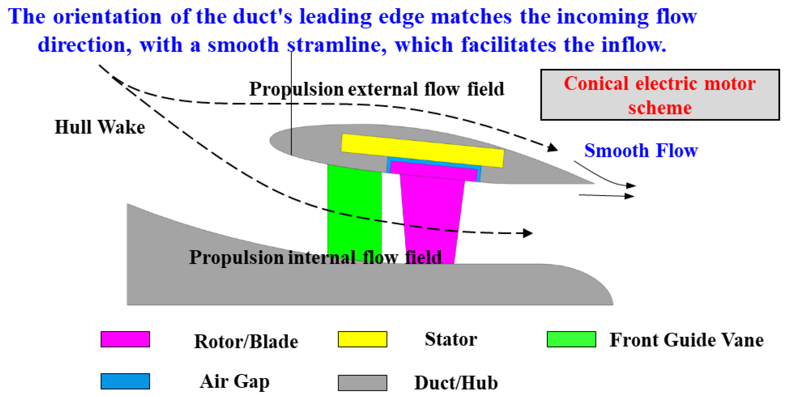
2. The Application of CPMSM in Shaftless RDT
2.1. The Geometric Compatibility of CPMSM in Shaftless RDT
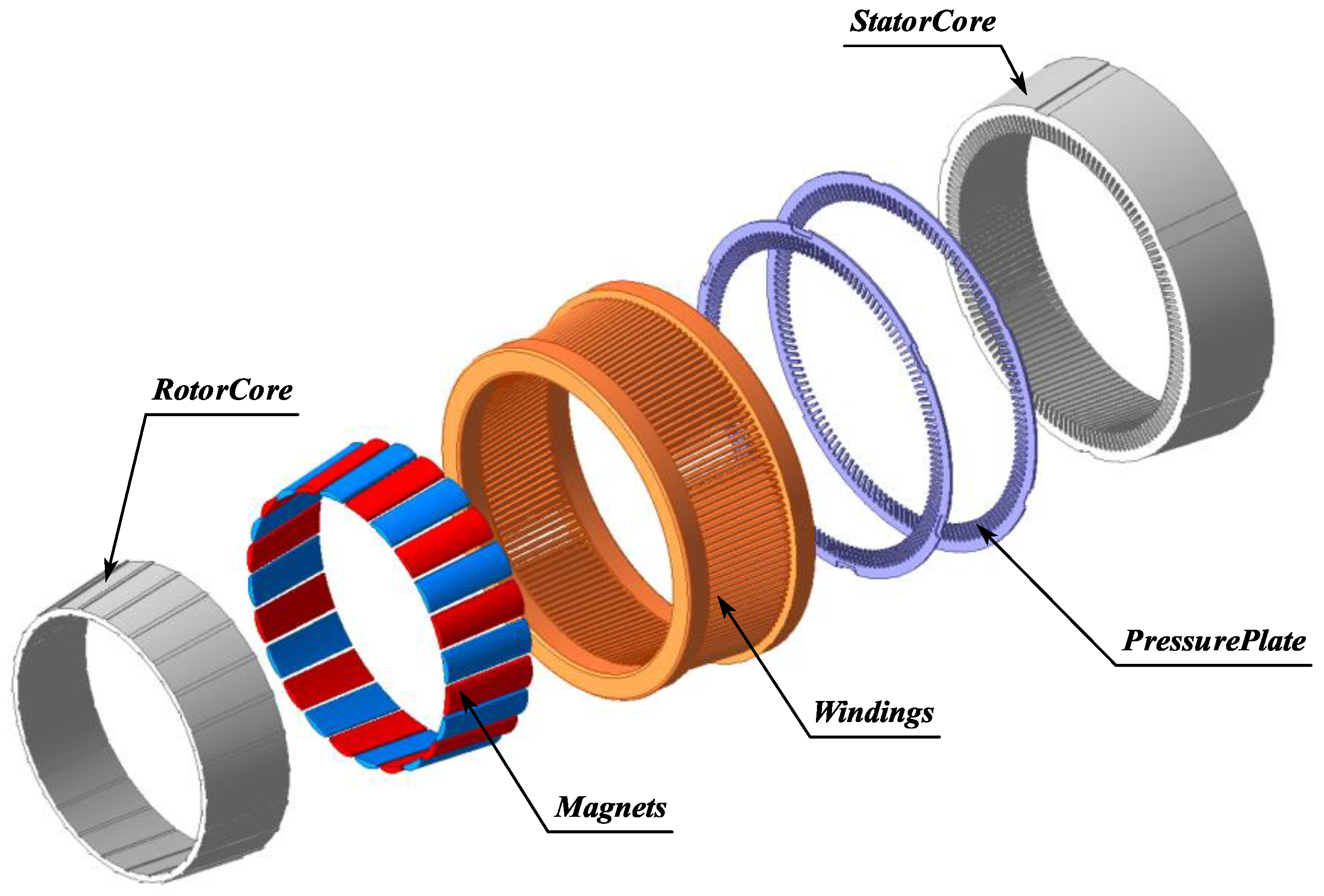
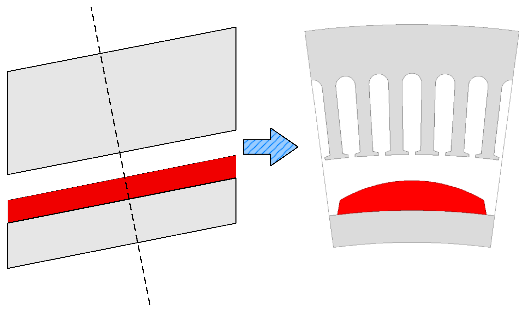
2.2. The Topological Structure of CPMSM
3. EMCM of CPMSM
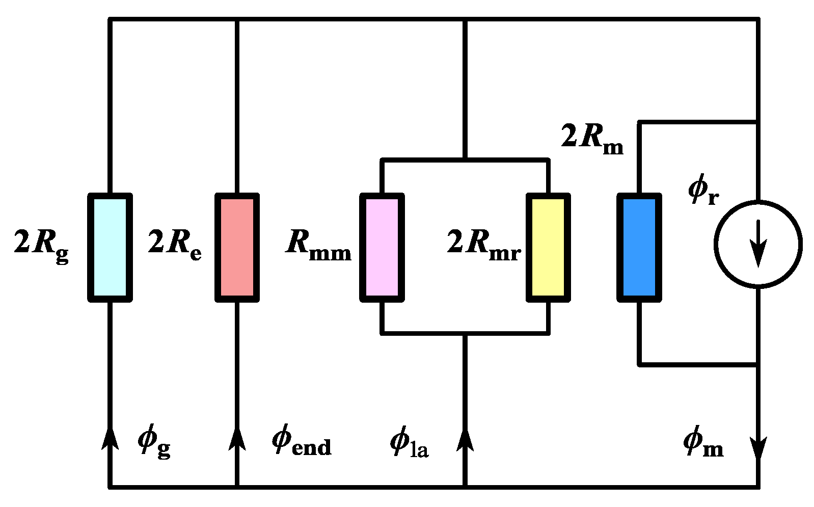
3.1. Magnetic Circuit of CPMSM
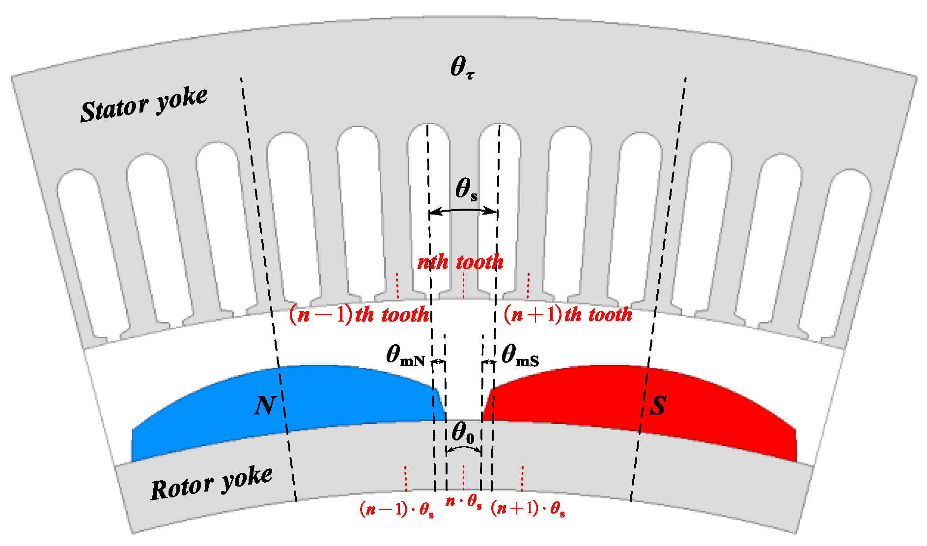
3.2. Modeling of Permanent Magnets
- Calculation of Stator Slot Pitch :
- 2.
- Calculation of Relative Tooth Pitch :
- 3.
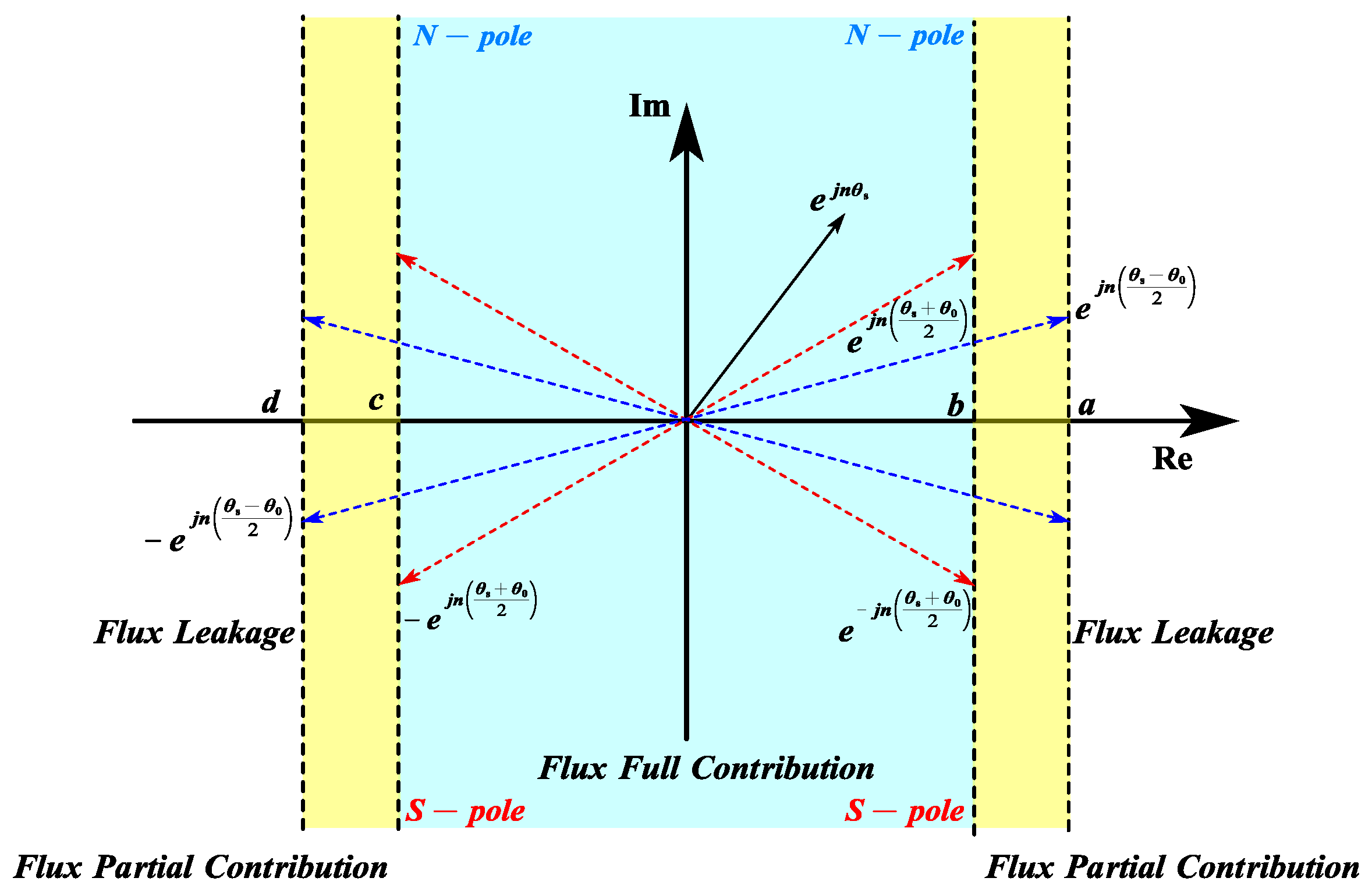
- Identification of Pole Polarity Associated with Stator Tooth:
- 4.
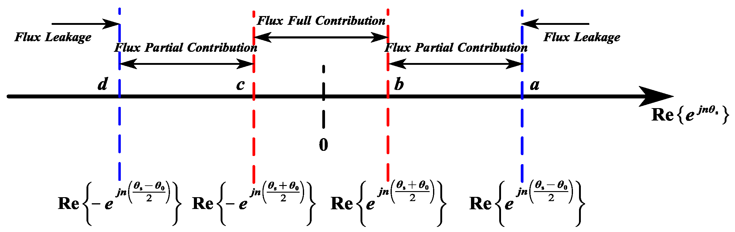
- Sorting of Relative Tooth Pitch :
- 5.
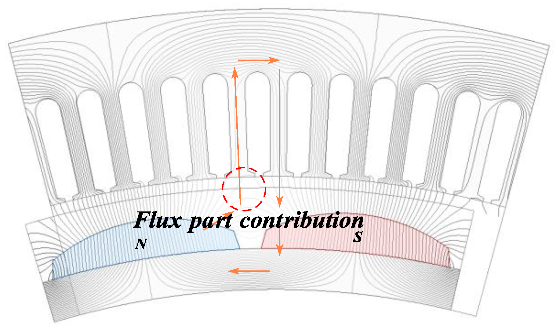
- Boundary Conditions for Flux Partial Contribution Mode:
- 6.
- Computational Methodology:
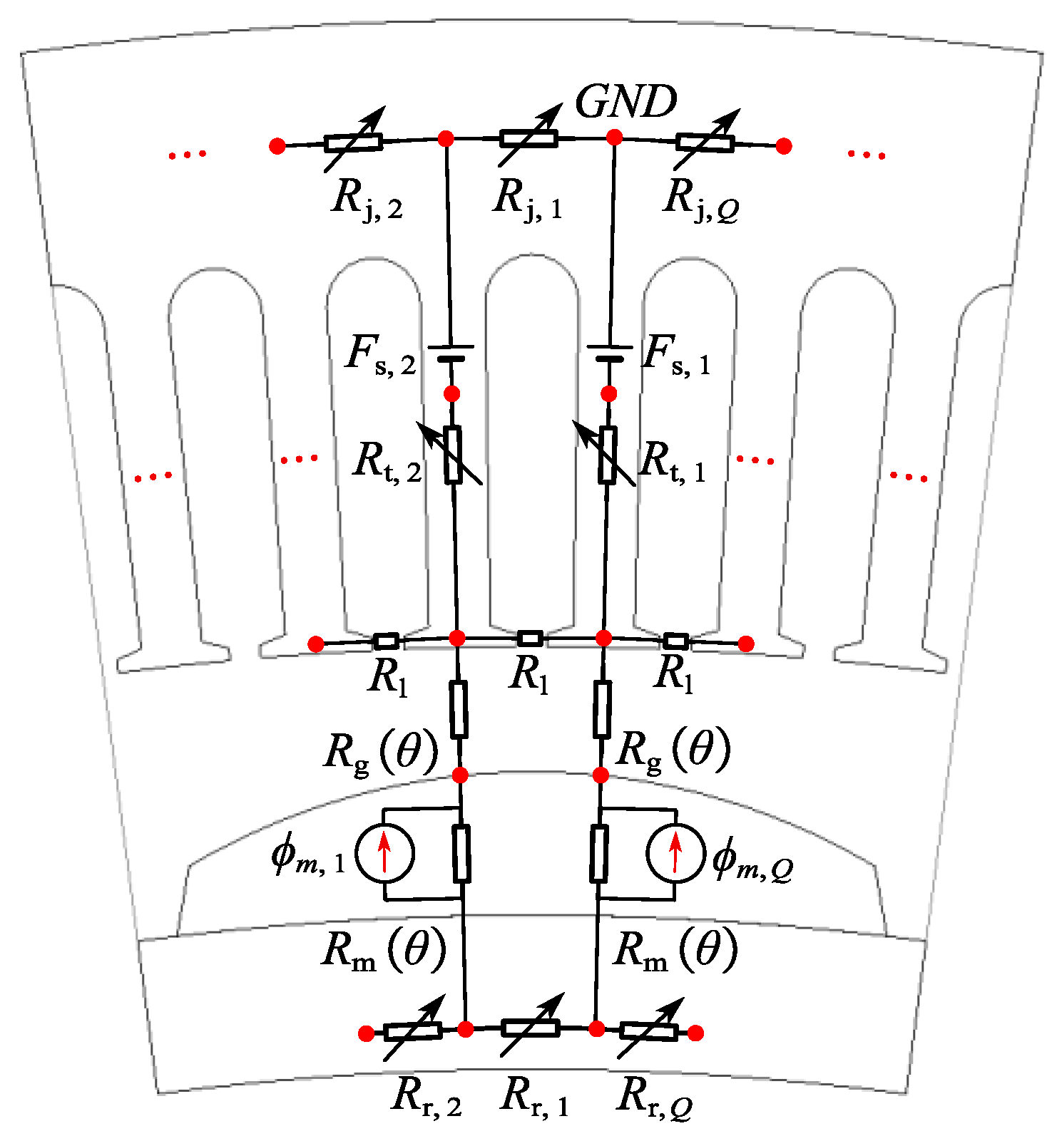
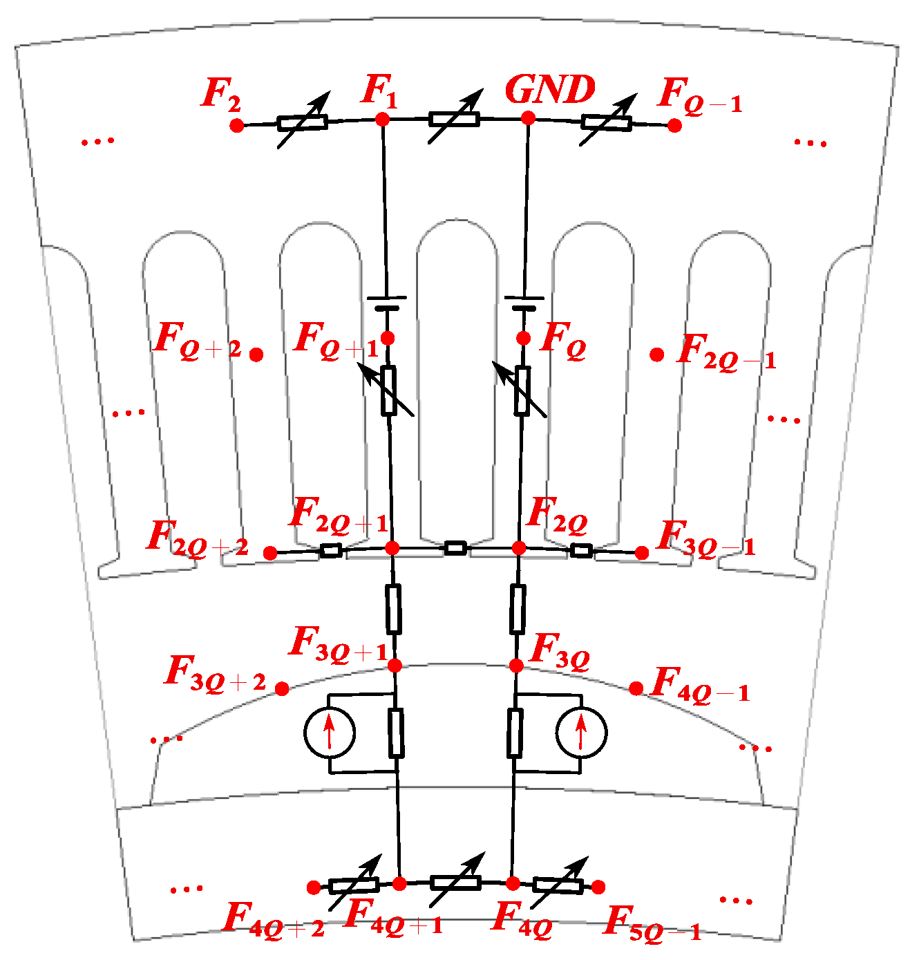
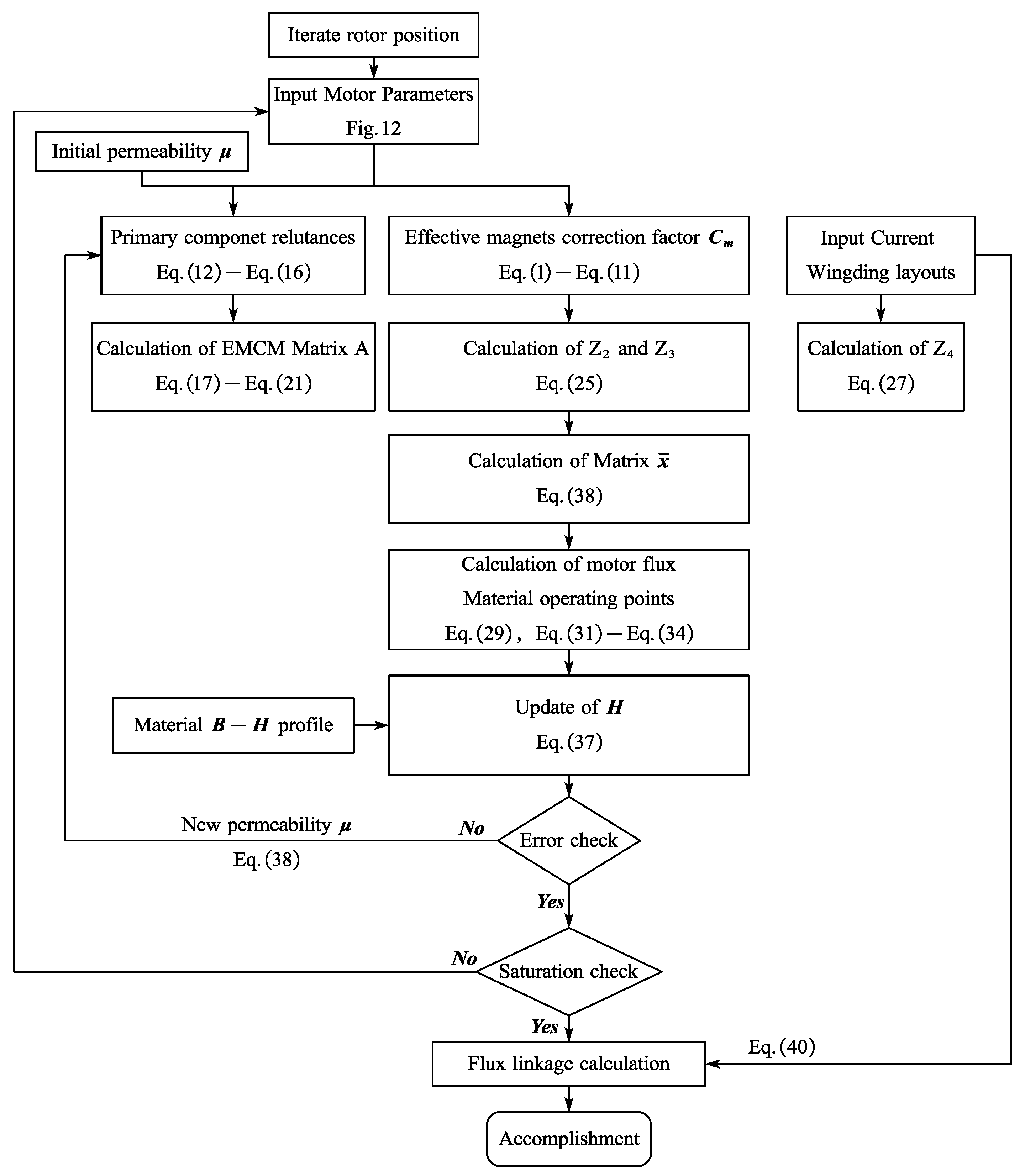
3.3. Modeling of CPMSM
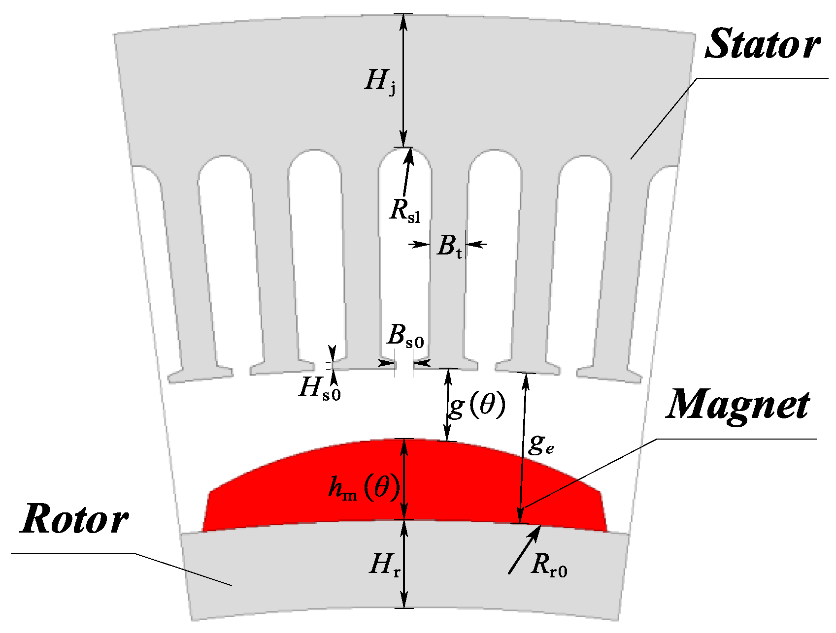
- As shown in Figure 13, the permeability of the stator and rotor cores is variable and represented by variable reluctance.
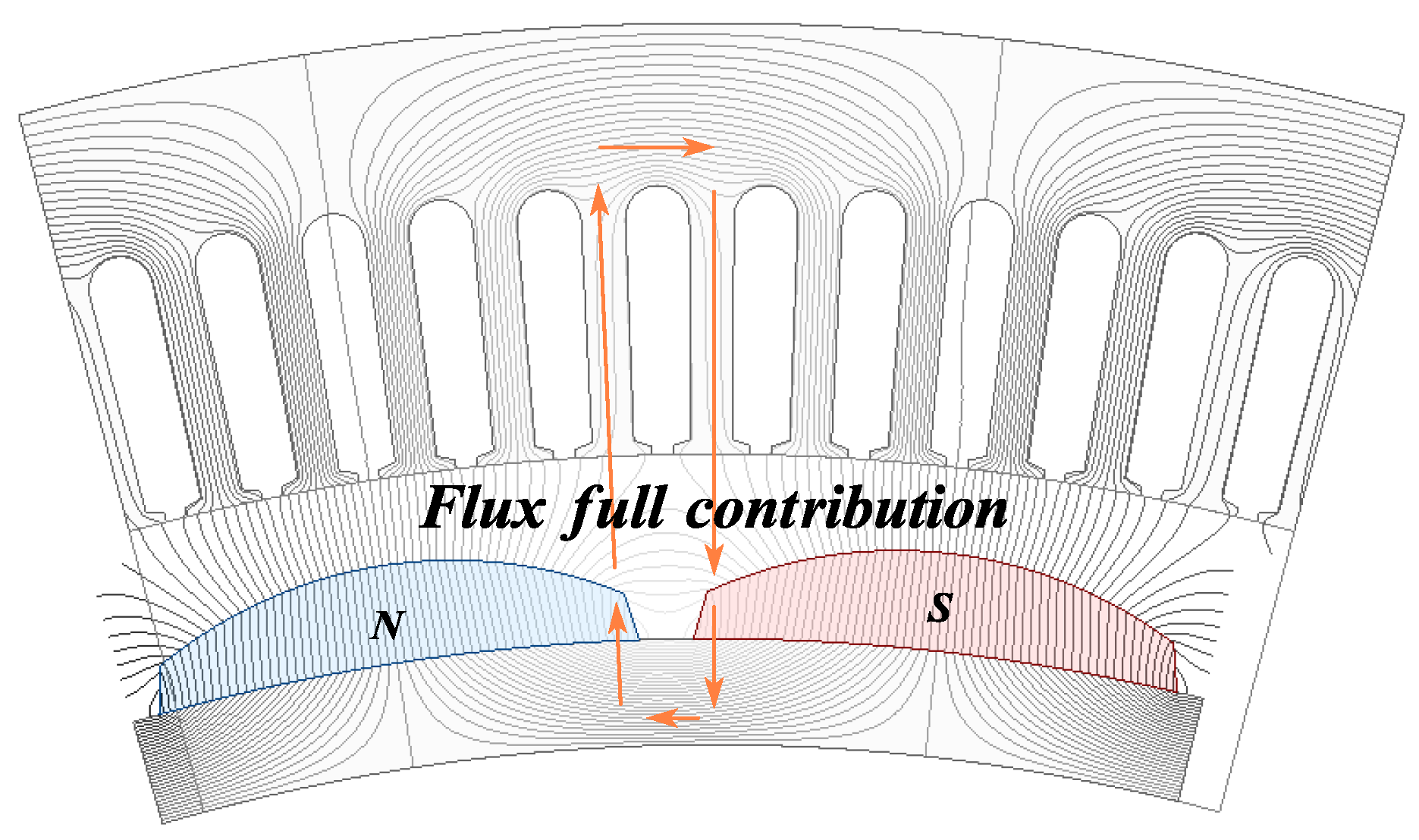
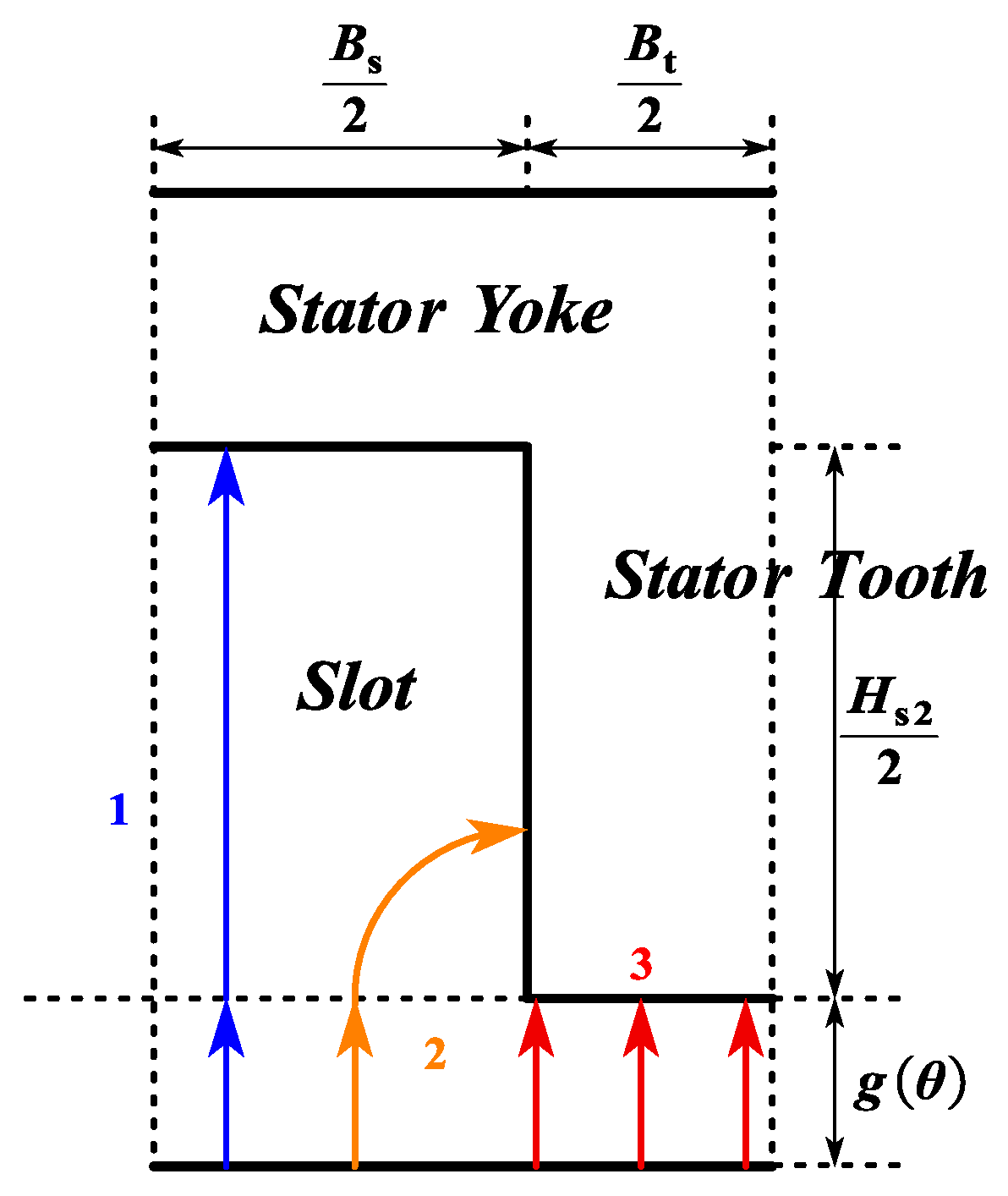
- The flux passing through a stator tooth evenly traverses the air gap within one slot pitch angle.
- Considering the impact of PM demagnetization on the electromagnetic performance of the CPMSM, the PM thickness and mechanical air gap length are defined as functions of .
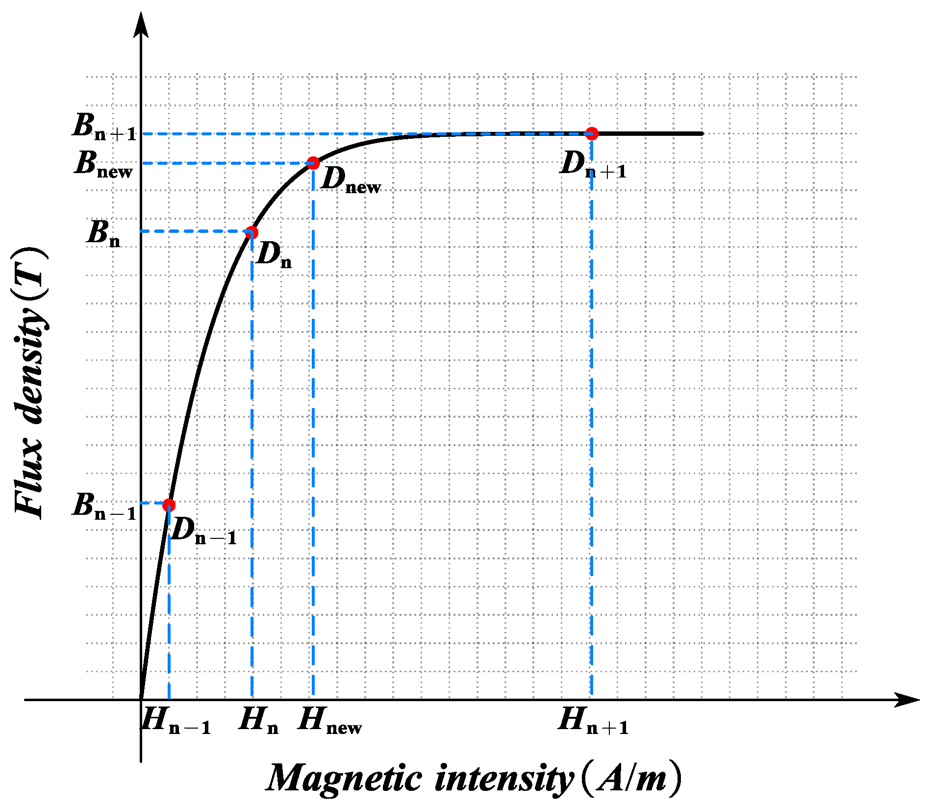
3.4. Nonlinearity of Ferromagnetic Materials
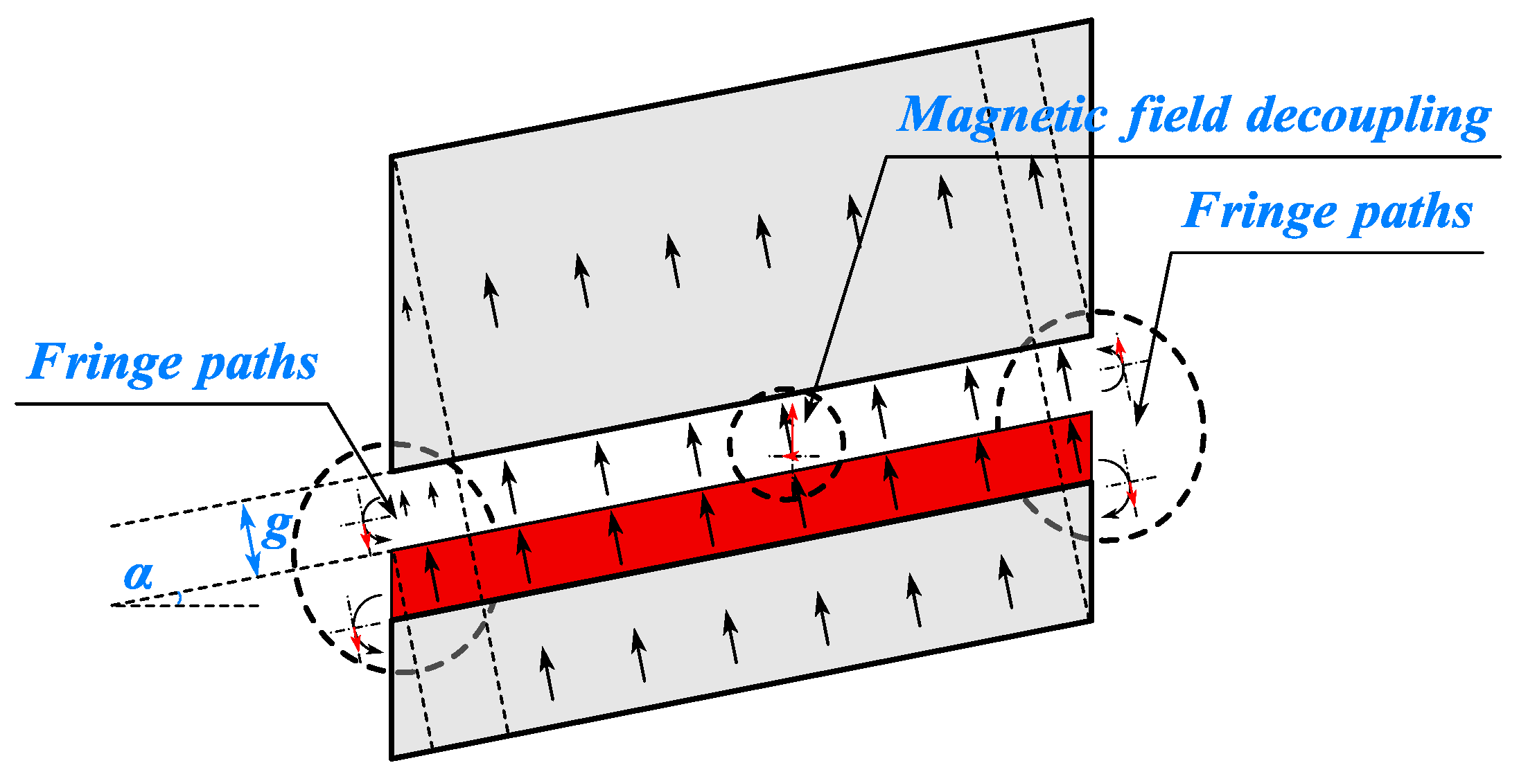
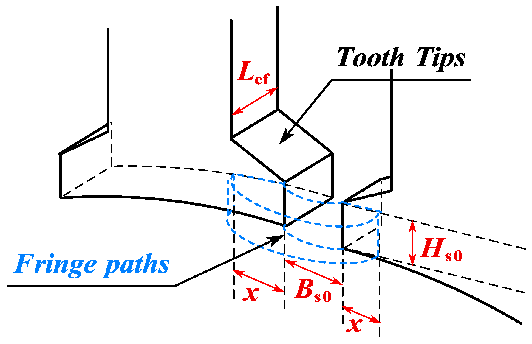
3.5. End Leakage Flux Coefficient of CPMSM
4. Calculation and Optimization of Electromagnetic Performance for CPMSM
4.1. Electromagnetic Performance of CPMSM
4.2. Electromagnetic Performance Optimization of CPMSM
5. FEA and Experimental Results Verification
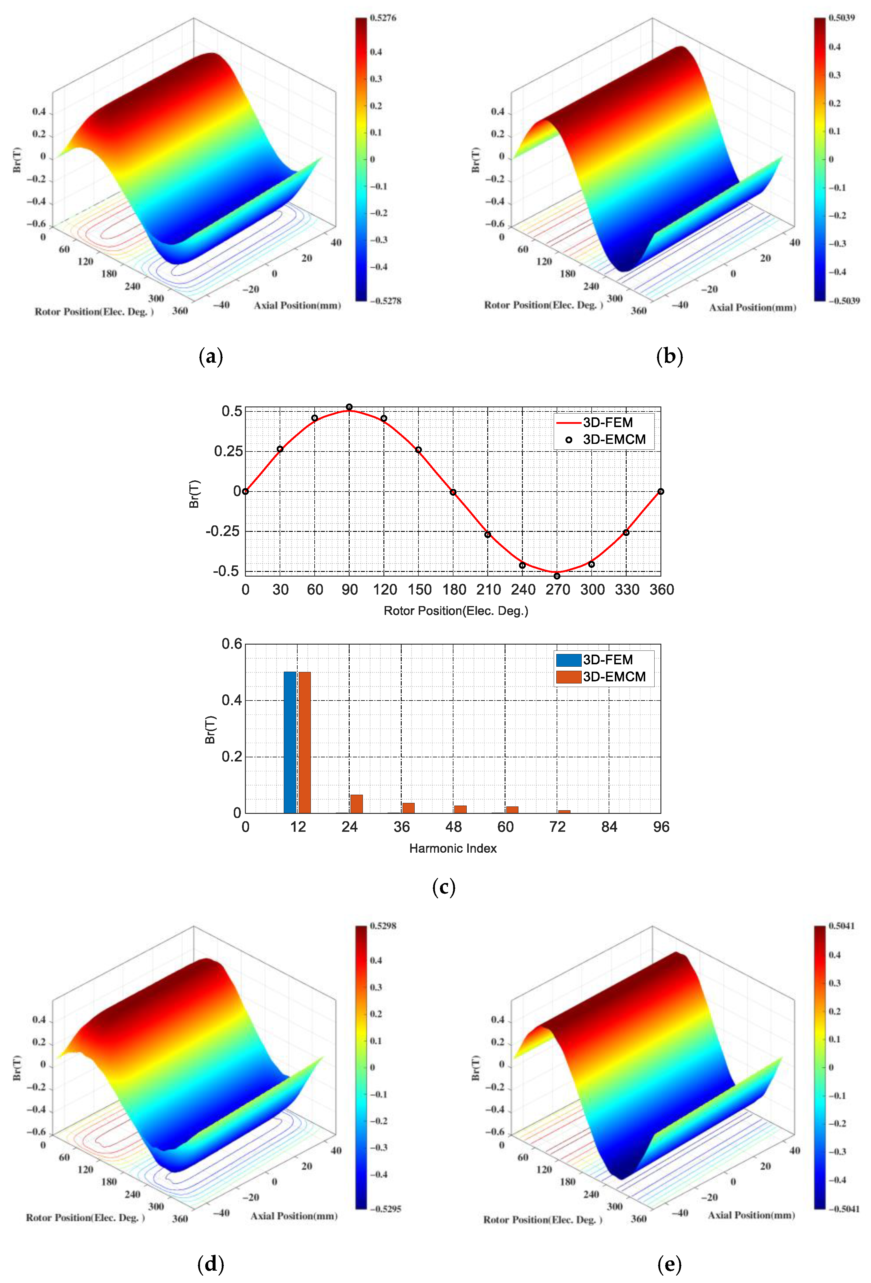
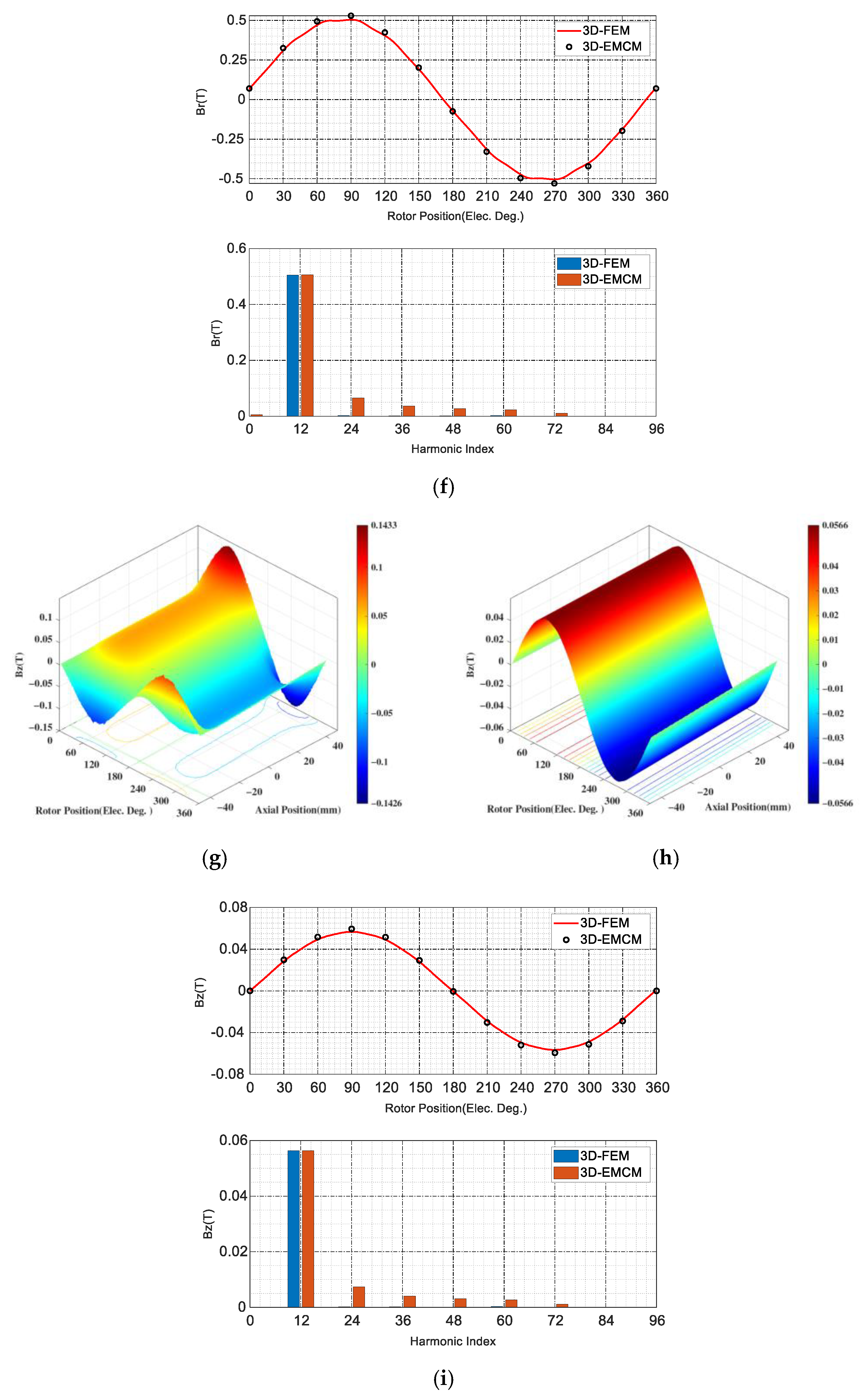
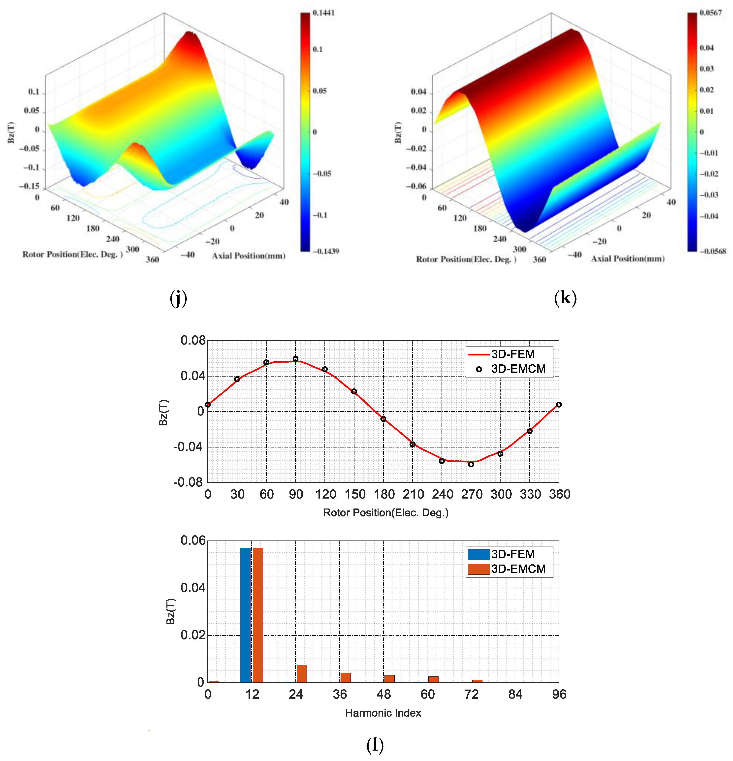
5.1. CPMSM with FEA Verification
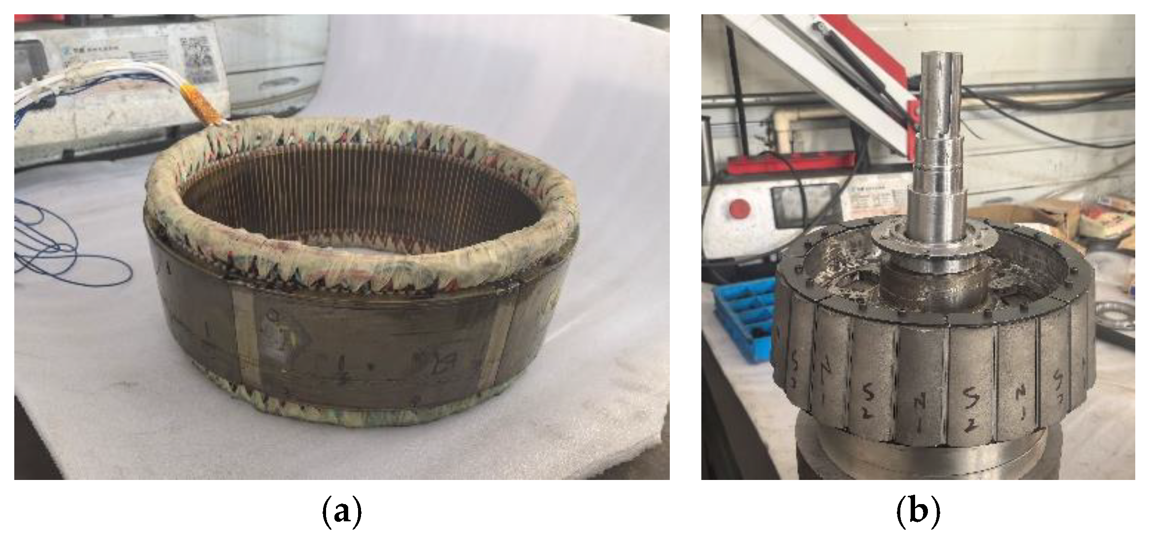
5.2. CPMSM with Experiment Verification
6. Conclusions
Author Contributions
Funding
Informed Consent Statement
Data Availability Statement
Conflicts of Interest
Appendix A
References
- Liu, C. Emerging Electric Machines and Drives—An Overview. IEEE Trans. Energy Convers. 2018, 33, 2270–2280. [Google Scholar] [CrossRef]
- Yan, X.; Liang, X.; Ouyang, W.; Liu, Z.; Liu, B.; Lan, J. A Review of Progress and Applications of Ship Shaft-Less Rim-Driven Thrusters. Ocean Eng. 2017, 144, 142–156. [Google Scholar] [CrossRef]
- Shen, Y.; Hu, P.; Jin, S.; Wei, Y.; Lan, R.; Zhuang, S.; Zhu, H.; Cheng, S.; Chen, J.; Wang, D.; et al. Design of Novel Shaftless Pump-Jet Propulsor for Multi-Purpose Long-Range and High-Speed Autonomous Underwater Vehicle. IEEE Trans. Magn. 2016, 52, 7403304. [Google Scholar] [CrossRef]
- Zhai, S.; Jin, S.; Chen, J.; Liu, Z.; Song, X. CFD-Based Multi-Objective Optimization of the Duct for a Rim-Driven Thruster. Ocean Eng. 2022, 264, 112467. [Google Scholar] [CrossRef]
- Liu, D.; Wang, G.; Li, W. Global Magnetic Field Distribution and Open Water Hydrodynamic Performance of a Flux-Modulated Rim-Driven Thruster. IEEE Trans. Magn. 2024, 60, 8205514. [Google Scholar] [CrossRef]
- Ojaghlu, P.; Vahedi, A. Specification and Design of Ring Winding Axial Flux Motor for Rim-Driven Thruster of Ship Electric Propulsion. IEEE Trans. Veh. Technol. 2019, 68, 1318–1326. [Google Scholar] [CrossRef]
- Bai, H.; Yu, B.; Ouyang, W.; Yan, X.; Zhu, J. HF-Based Sensorless Control of a FTPMM in Ship Shaftless Rim-Driven Thruster System. IEEE Trans. Intell. Transp. Syst. 2022, 23, 16867–16877. [Google Scholar] [CrossRef]
- Hao, Z.; Shuanbao, J.; Dong, W.; Gongbao, W.; Pengfei, H. Design and Analysis of the Integrated Motor Cooling System for Shaftless Propeller. IEEE Access 2019, 7, 174573–174582. [Google Scholar] [CrossRef]
- Hassannia, A.; Darabi, A. Design and Performance Analysis of Superconducting Rim-Driven Synchronous Motors for Marine Propulsion. IEEE Trans. Appl. Supercond. 2014, 24, 40–46. [Google Scholar] [CrossRef]
- Yuan, B.; Chen, P.; Wang, E.; Yu, J.; Wang, J. A Systematic Optimization Method for Permanent Magnet Synchronous Motors Based on SMS-EMOA. Sensors 2024, 24, 2956. [Google Scholar] [CrossRef]
- Ni, S.; Bauw, G.; Romary, R.; Cassoret, B.; Le Besnerais, J. Damper Winding for Noise and Vibration Reduction of a Permanent Magnet Synchronous Machine. Sensors 2022, 22, 2738. [Google Scholar] [CrossRef] [PubMed]
- Hu, P.; Wang, D.; Jin, S.; Wei, Y.; Chen, C.; Lin, N.; Zhang, Q.; Wu, X.; Zhu, H.; Sun, F. The Modified Model of Third-Harmonic Shaping for a Surface-Mounted Permanent-Magnet Synchronous Motor Under Parallel Magnetization. IEEE Trans. Ind. Appl. 2020, 56, 4847–4856. [Google Scholar] [CrossRef]
- Liu, F.; Wang, X.; Xing, Z.; Ren, J.; Li, X. Analysis and Research on No-Load Air Gap Magnetic Field and System Multiobjective Optimization of Interior PM Motor. IEEE Trans. Ind. Electron. 2022, 69, 10915–10925. [Google Scholar] [CrossRef]
- Cai, B.; Xu, Q.; Tian, B.; Qiu, L.; Chai, W.; Qi, J.; He, L. Improvement of the Efficiency for Rim-Driven Thrusters through Acceleration of Gap Flow. Ocean Eng. 2024, 291, 116480. [Google Scholar] [CrossRef]
- Liu, B.; Vanierschot, M.; Buysschaert, F. Optimization Design of the Duct of a Rim-Driven Thruster Using the Adjoint Approach. Ocean Eng. 2023, 278, 114293. [Google Scholar] [CrossRef]
- Zhang, Z.; Liu, B.; Ouyang, W.; Zheng, R.; Vanierschot, M. Analysis of the Energy Loss Mechanism of a Rim-Driven Thruster under Open Water Conditions. Ocean Eng. 2025, 319, 120203. [Google Scholar] [CrossRef]
- Liu, B.; Vanierschot, M.; Buysschaert, F. Effects of Transition Turbulence Modeling on the Hydrodynamic Performance Prediction of a Rim-Driven Thruster under Different Duct Designs. Ocean Eng. 2022, 256, 111142. [Google Scholar] [CrossRef]
- Wang, J.; Huang, S.; Guo, C.; Feng, Y. Magnetic Field and Operating Performance Analysis of Conical-Rotor Permanent Magnet Synchronous Motor. CES Trans. Electr. Mach. Syst. 2018, 2, 181–187. [Google Scholar] [CrossRef]
- Roggia, S.; Cupertino, F.; Gerada, C.; Galea, M. A Two-Degrees-of-Freedom System for Wheel Traction Applications. IEEE Trans. Ind. Electron. 2018, 65, 4483–4491. [Google Scholar] [CrossRef]
- Wang, J.; Huang, S.; Guo, C.; Wu, H.; Feng, Y. Direct-Drive Conical-Rotor Permanent Magnet Synchronous Generator for Turbo-Expander, Accounting for Adaptive Equilibrium of Axial Force. IEEE Access 2018, 6, 72889–72899. [Google Scholar] [CrossRef]
- Chai, F.; Zhao, K.; Li, Z.; Gan, L. Flux Weakening Performance of Permanent Magnet Synchronous Motor With a Conical Rotor. IEEE Trans. Magn. 2017, 53, 8208506. [Google Scholar] [CrossRef]
- Roggia, S.; Cupertino, F.; Gerada, C.; Galea, M. Axial Position Estimation of Conical Shaped Motors for Aerospace Traction Applications. IEEE Trans. Ind. Appl. 2017, 53, 5405–5414. [Google Scholar] [CrossRef]
- Liang, L.; Liang, P.; Liu, C.; Zhang, D.; Fan, Y.; Zhang, X.; Liu, W. Analysis of the Matching between the Electric Propulsion Conical Motor in Electric Aircraft and the Propeller Based on Axial Force and Torque. IEEE Trans. Transp. Electrif. 2024, 1. [Google Scholar] [CrossRef]
- Hsieh, M.-F.; Hsu, Y.-C. A Generalized Magnetic Circuit Modeling Approach for Design of Surface Permanent-Magnet Machines. IEEE Trans. Ind. Electron. 2012, 59, 779–792. [Google Scholar] [CrossRef]
- Cao, D.; Zhao, W.; Ji, J.; Wang, Y. Parametric Equivalent Magnetic Network Modeling Approach for Multiobjective Optimization of PM Machine. IEEE Trans. Ind. Electron. 2021, 68, 6619–6629. [Google Scholar] [CrossRef]
- Qu, R.; Lipo, T.A. Analysis and Modeling of Air-Gap and Zigzag Leakage Fluxes in a Surface-Mounted Permanent-Magnet Machine. IEEE Trans. Ind. Appl. 2004, 40, 121–127. [Google Scholar] [CrossRef]
- Wang, D.; Wu, X.; Chen, J.; Guo, Y.; Cheng, S. A Distributed Magnetic Circuit Approach to Analysis of Multiphase Induction Machines With Nonsinusoidal Supply. IEEE Trans. Energy Convers. 2015, 30, 522–532. [Google Scholar] [CrossRef]
- Jiang, H.; Su, Z.; Wang, D. Analytical Calculation of Active Magnetic Bearing Based on Distributed Magnetic Circuit Method. IEEE Trans. Energy Convers. 2021, 36, 1841–1851. [Google Scholar] [CrossRef]
- Li, J.; Wu, L. A Nonlinear 3-D Hybrid Model for Surface-Mounted Permanent Magnet Machines Considering End Effect. IEEE Trans. Ind. Electron. 2024, 71, 8590–8600. [Google Scholar] [CrossRef]
- Jiang, N.; Cao, R.; Sun, W.; Chen, D.; Wang, K. MRAS-Based Sensorless Control of PMSM Drives Using Extended State Observer in Shaftless Rim-Driven Thruster System. IEEE Trans. Transp. Electrif. 2024, 1. [Google Scholar] [CrossRef]
- Carter, F.W. The Magnetic Field of the Dynamo-Electric Machine. J. Inst. Electr. Eng. 1926, 64, 1115–1138. [Google Scholar] [CrossRef]


| Parameters | Values |
|---|---|
| Rated speed (rpm) | 630 |
| Rated power (kW) | 10.5 |
| Rated torque (N·m) | 160 |
| Rated voltage (V) | 200 |
| Rated current (A) | 30 |
| Slot fill factor (%) | |
| Current density (A/mm2) | |
| Air gap length (mm) | 6 |
| Taper angle (degree) | 6.7 |
| Parameters | Values |
|---|---|
| Stator core outer diameter (mm) | 365/387.08 |
| Stator core inner diameter (mm) | 305/327.08 |
| Rotor core outer diameter (mm) | 293/315.08 |
| Rotor core inner diameter (mm) | 264/286.08 |
| Number of pole pairs | 12 |
| Number of slots | 144 |
| Maximum air gap flux density (T) | 0.52 |
| Maximum stator tooth flux density (T) | 1.25 |
| Maximum stator yoke flux density (T) | 1.10 |
| Maximum rotor yoke flux density (T) | 1.15 |
| Maximum magnet thickness (mm) | 6.85 |
| Permanent magnet material | SmCo30H |
| Slot opening (mm) | 1.5 |
| Stator tooth tip height (mm) | 0.6 |
| Stator tooth width (mm) | 2.7 |
| Stator tooth height (mm) | 15.5 |
| Rsl (mm) | 176.8 |
| Rr0 (mm) | 145.2 |
| Stator yoke thickness (mm) | 11.3 |
| Rotor yoke thickness (mm) | 7.3 |
| Stator lamination thickness (mm) | 0.35 |
| Effective axial length of the motor (mm) | 94 |
Disclaimer/Publisher’s Note: The statements, opinions and data contained in all publications are solely those of the individual author(s) and contributor(s) and not of MDPI and/or the editor(s). MDPI and/or the editor(s) disclaim responsibility for any injury to people or property resulting from any ideas, methods, instructions or products referred to in the content. |
© 2025 by the authors. Licensee MDPI, Basel, Switzerland. This article is an open access article distributed under the terms and conditions of the Creative Commons Attribution (CC BY) license (https://creativecommons.org/licenses/by/4.0/).
Share and Cite
Cui, F.; Chen, J.; Hu, P.; Wu, X.; Sun, F. An Equivalent Magnetic-Circuit-Modeling Approach for Analysis of Conical Permanent Magnet Synchronous Motor. Sensors 2025, 25, 1788. https://doi.org/10.3390/s25061788
Cui F, Chen J, Hu P, Wu X, Sun F. An Equivalent Magnetic-Circuit-Modeling Approach for Analysis of Conical Permanent Magnet Synchronous Motor. Sensors. 2025; 25(6):1788. https://doi.org/10.3390/s25061788
Chicago/Turabian StyleCui, Fengrui, Junquan Chen, Pengfei Hu, Xingyu Wu, and Fangxu Sun. 2025. "An Equivalent Magnetic-Circuit-Modeling Approach for Analysis of Conical Permanent Magnet Synchronous Motor" Sensors 25, no. 6: 1788. https://doi.org/10.3390/s25061788
APA StyleCui, F., Chen, J., Hu, P., Wu, X., & Sun, F. (2025). An Equivalent Magnetic-Circuit-Modeling Approach for Analysis of Conical Permanent Magnet Synchronous Motor. Sensors, 25(6), 1788. https://doi.org/10.3390/s25061788