


Wearable Arduino-Based Electronic Interactive Tattoo: A New Type of High-Tech Humanized Emotional Expression for Electronic Skin

 ,
,
Abstract
:1. Introduction
1.1. History of Skin Decoration
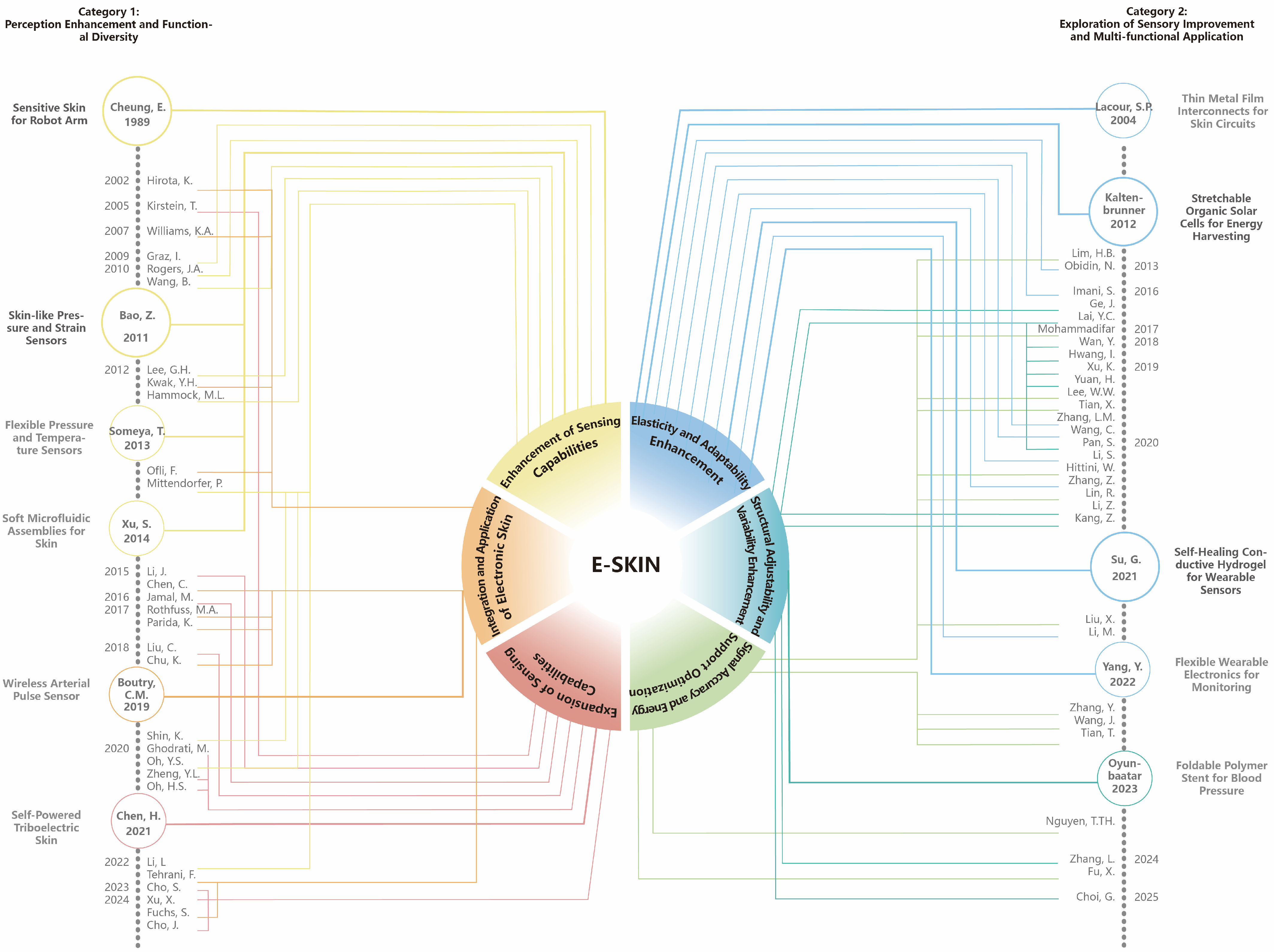
1.2. Literature Review
1.2.1. Perception Enhancement and Functional Diversity
- (1)
- Enhancement of sensing capabilities
- (2)
- Expansion of sensing capabilities
- (3)
- Integration and Application of Electronic Skin
1.2.2. Exploration of Sensory Improvement and Multi-Functional Application
- (1)
- Elasticity and adaptability enhancement
- (2)
- Structural adjustability and variability enhancement
- (3)
- Signal accuracy and energy support optimization
1.3. Electronic Interactive Tattoo
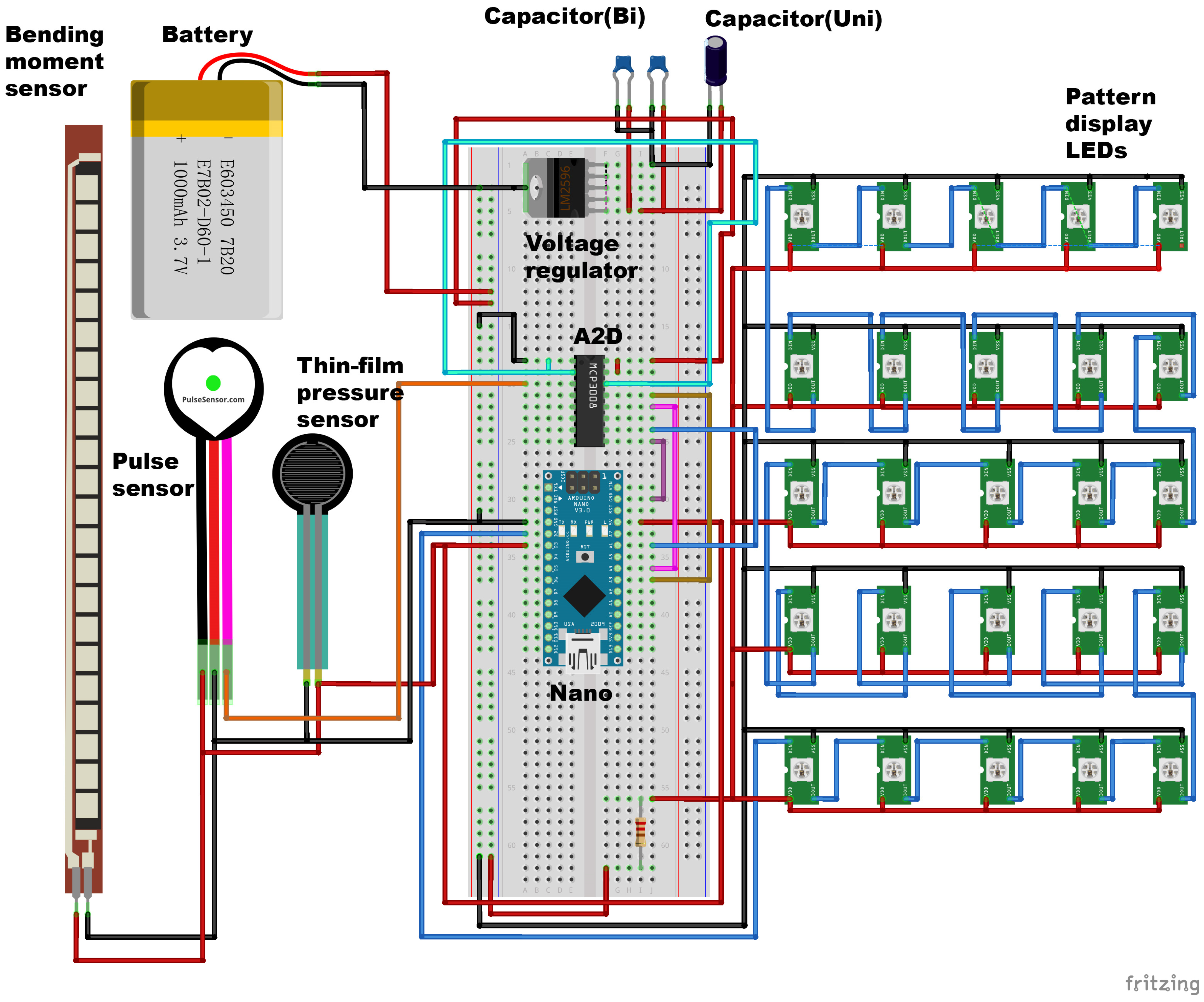
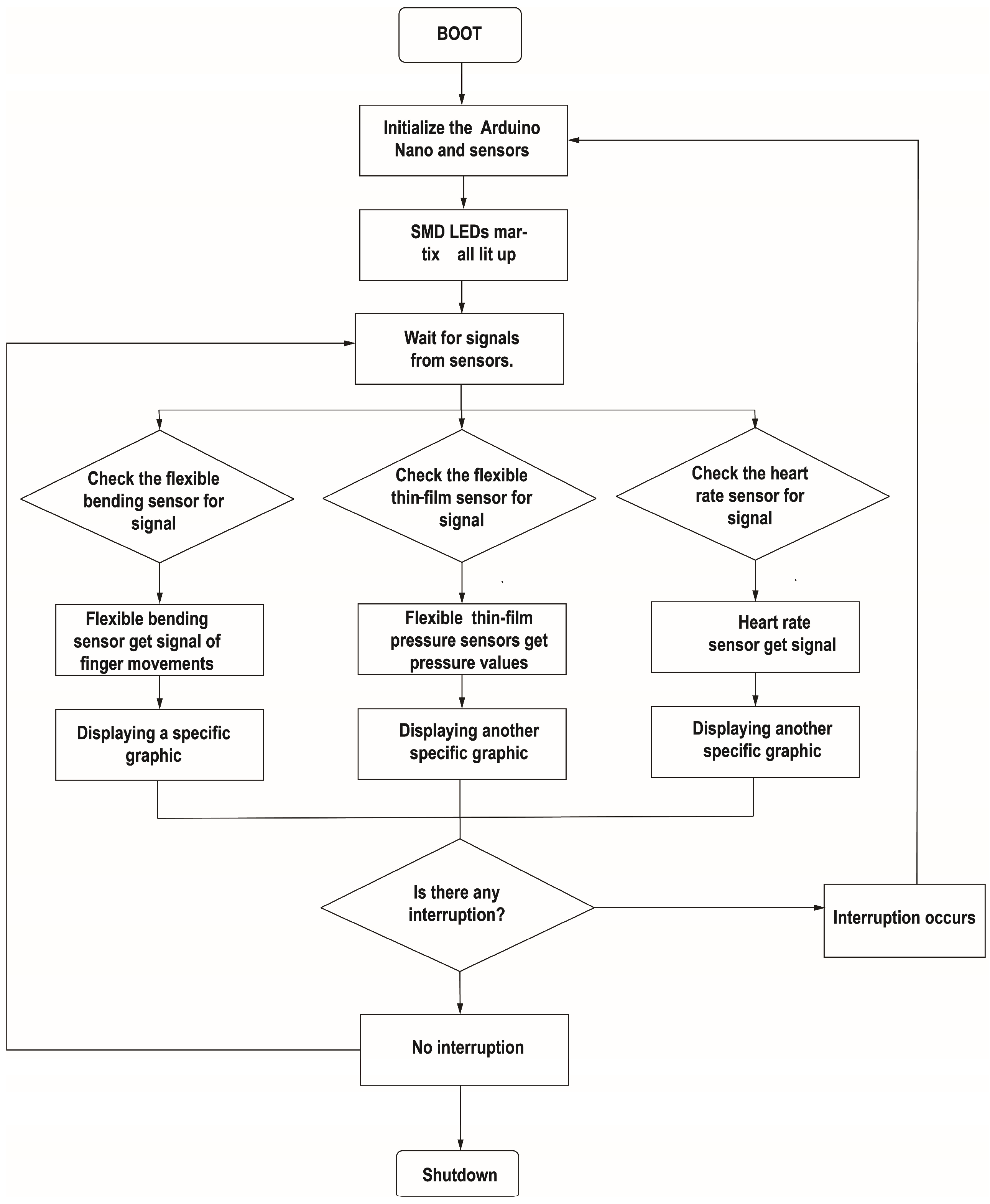
2. System Requirements and Design
2.1. Basis of the System Design
2.2. Choice of Hardware
2.3. Open-Source Programming
3. Functional Validation
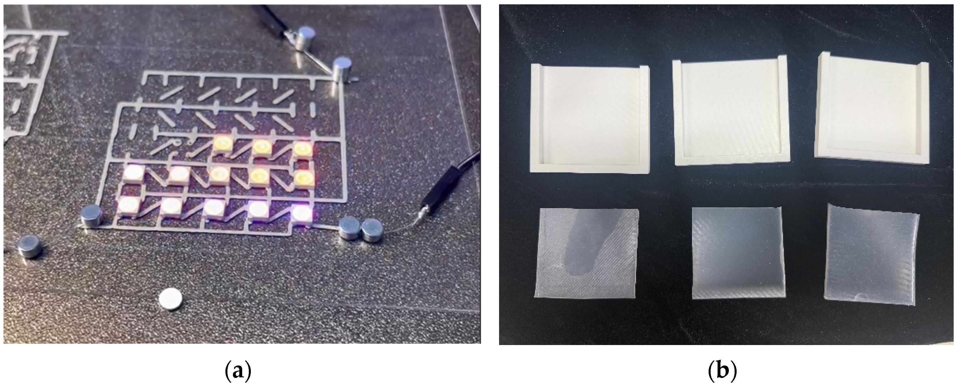
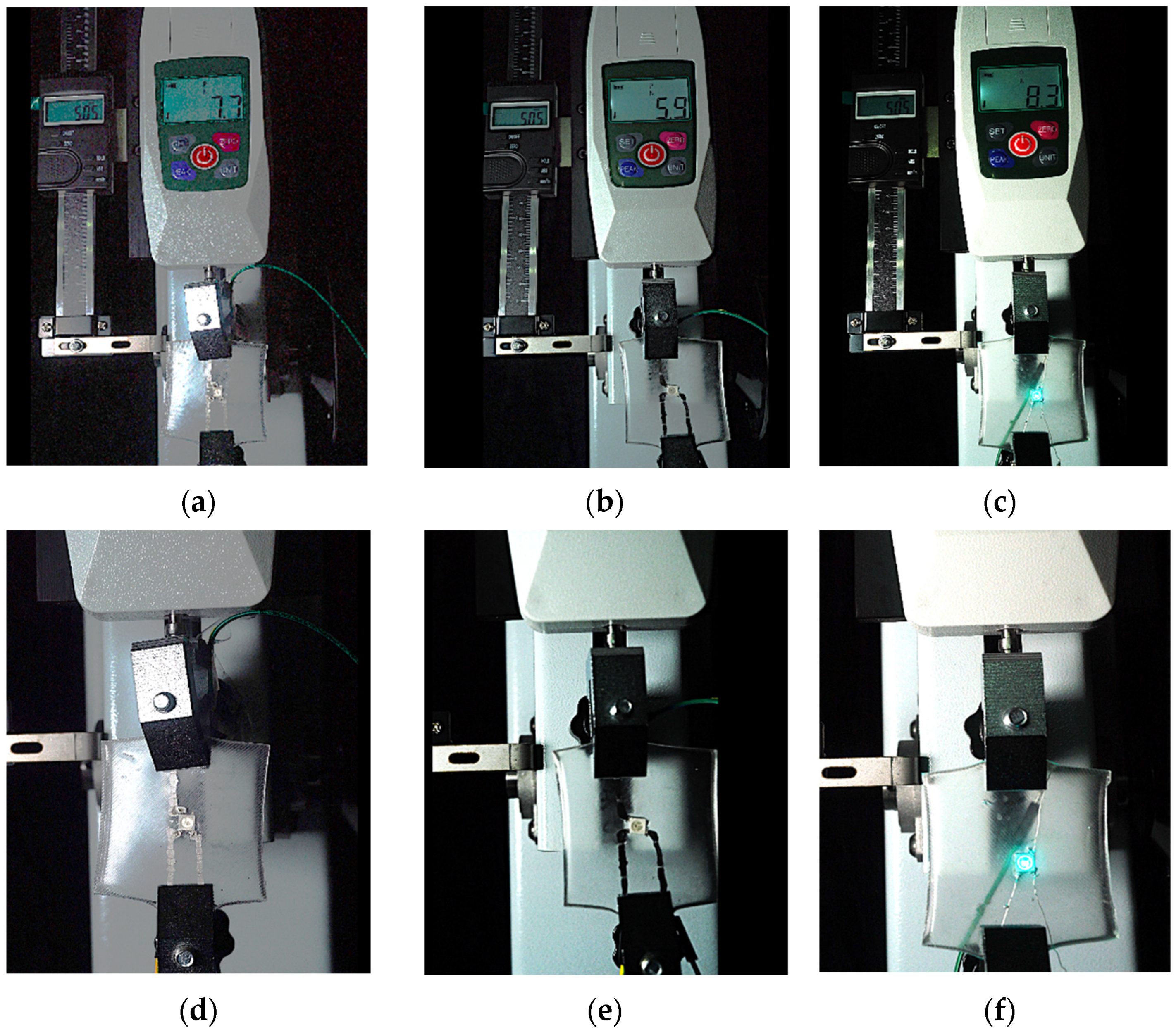
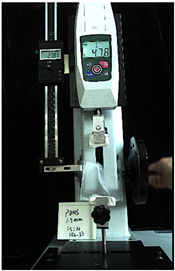
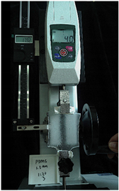
3.1. Substrate Material
3.2. Comparison of Conductive Materials
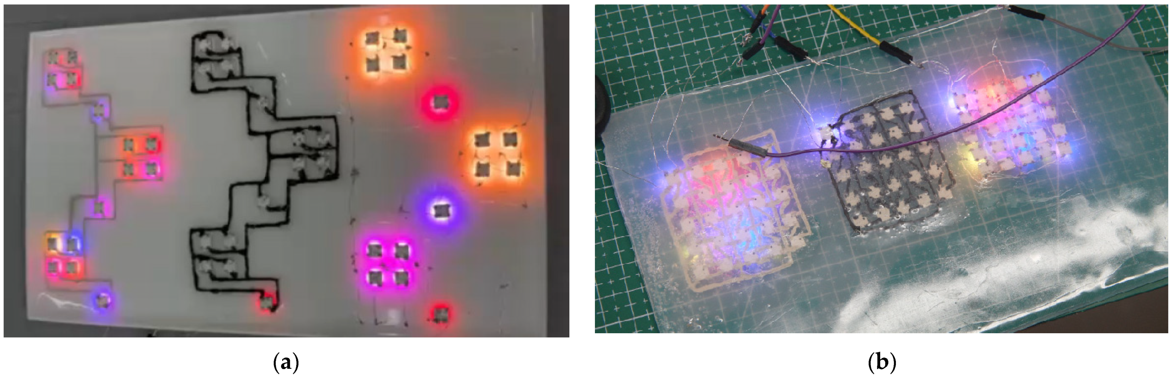
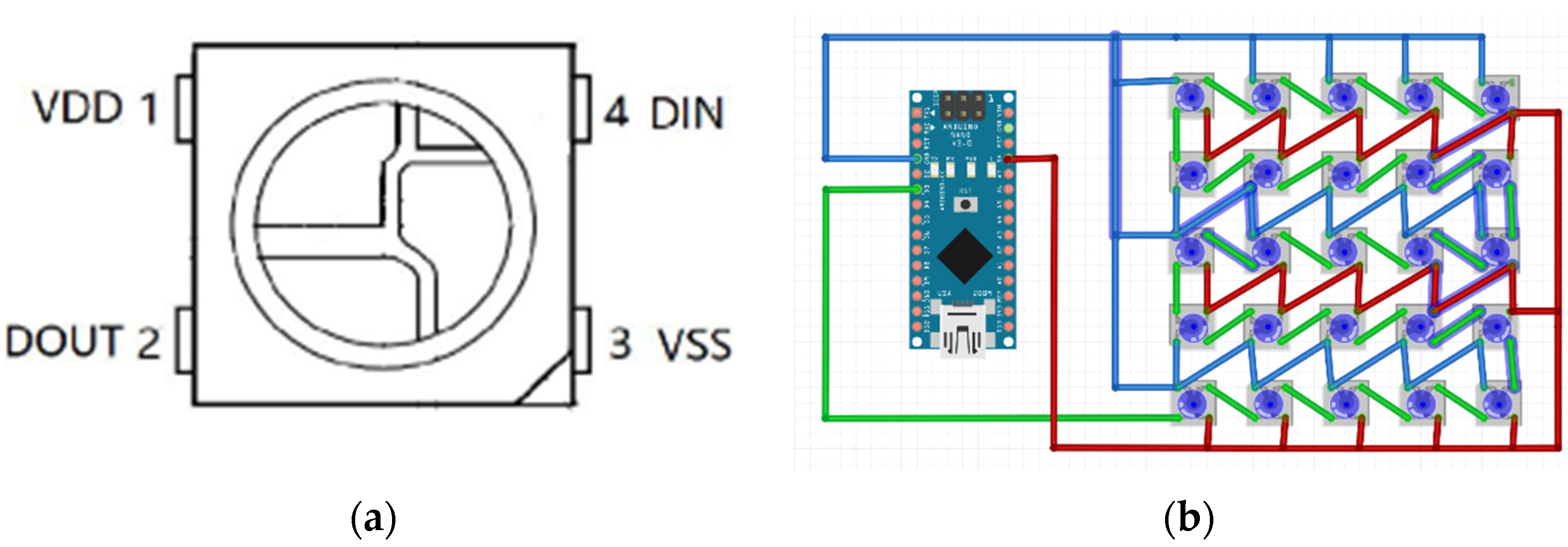
3.3. Pattern Display Material
- is the load current and is calculated with a maximum current of 20 mA × 25 lamp beads.
- is the ripple voltage, and WABEIT requires the current to be controlled at 2–6 mA; therefore, the ripple voltage is set to 0.1 V.
- is the power supply frequency, which is assumed to be 50 Hz.
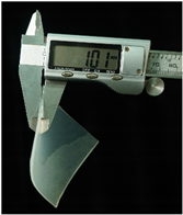
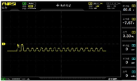
3.4. Verification of Thin-Film Pressure Sensor
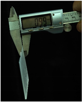
3.5. Verification of Bending-Moment Sensor
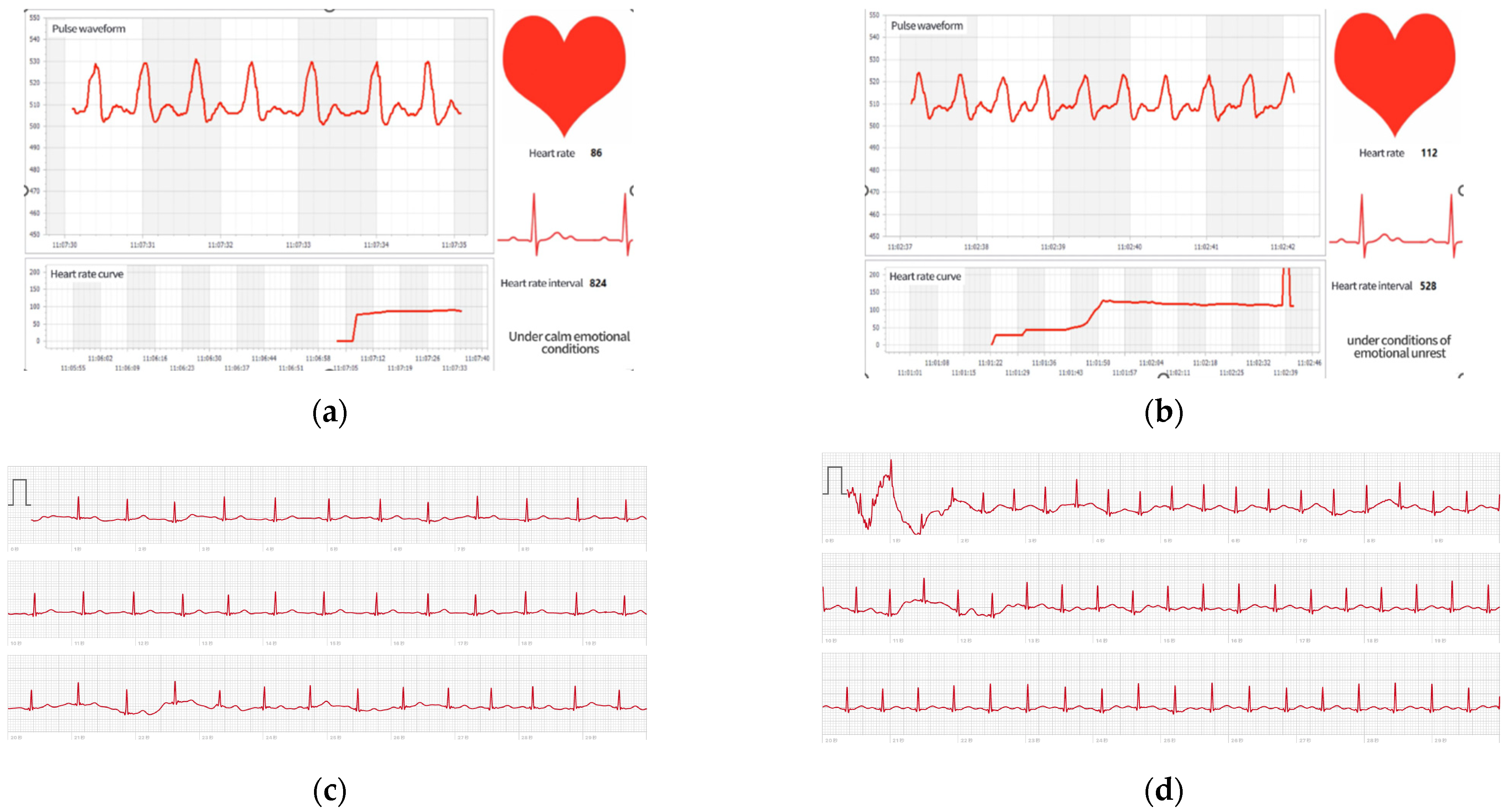
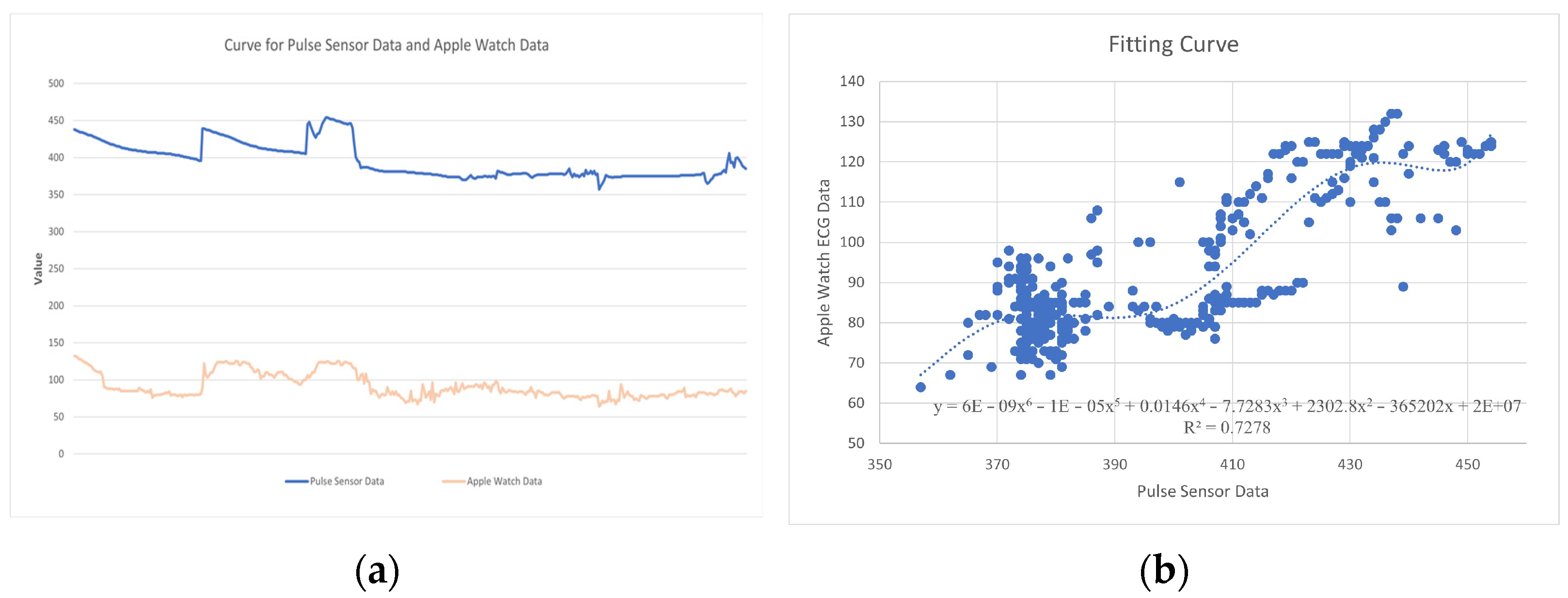
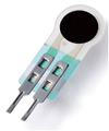
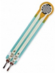
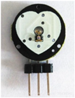
3.6. Heart-Rate Pulse Sensor
4. Discussion
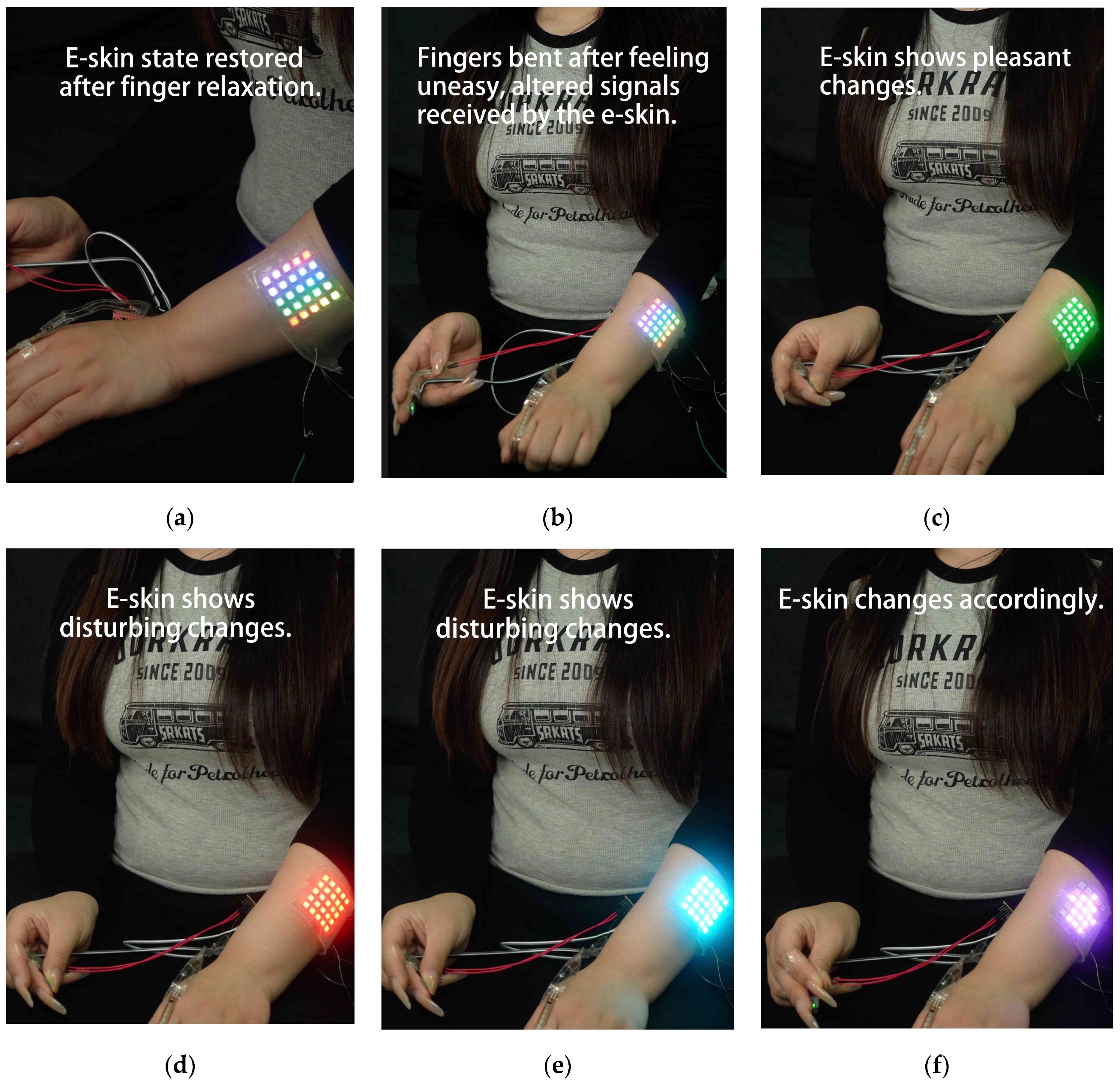
4.1. Input and Output Settings
4.2. Results
5. Conclusions
Author Contributions
Funding
Institutional Review Board Statement
Data Availability Statement
Conflicts of Interest
References
- Warrant, E.J.; Locket, A. Vision in the deep sea. Biol. Rev. 2004, 79, 671–712. [Google Scholar] [CrossRef]
- Davis, M.P.; Sparks, J.S.; Smith, W.L. Repeated and widespread evolution of bioluminescence in marine fishes. PLoS ONE 2016, 11, e0155154. [Google Scholar] [CrossRef]
- Mallefet, J.; Stevens, D.W.; Duchatelet, L. Bioluminescence of the largest luminous vertebrate, the kitefin shark, Dalatias licha: First insights and comparative aspects. Front. Mar. Sci. 2021, 8, 633582. [Google Scholar] [CrossRef]
- Edwards, C.; Marks, R. Evaluation of biomechanical properties of human skin. Clin. Dermatol. 1995, 13, 375–380. [Google Scholar] [CrossRef]
- Deter-Wolf, A.; Robitaille, B.; Krutak, L.; Galliot, S. The world’s oldest tattoos. J. Archaeol. Sci. Rep. 2016, 5, 19–24. [Google Scholar] [CrossRef]
- Fouquet, D.M. Le Tatouage Médical en Égypte dans L’antiquité et à L’époque Actuelle; G. Masson: Paris, France, 1898. [Google Scholar]
- Levin, J. Tattoos and Indigenous Peoples; The Rosen Publishing Group, Inc.: New York, NY, USA, 2008. [Google Scholar]
- Jones, C.P. 1 Stigma and Tattoo. In Written on the Body: The Tattoo in European and American History; Caplan, J., Ed.; Princeton University Press: Princeton, NJ, USA, 2000; pp. 1–16. [Google Scholar] [CrossRef]
- O’Brien, S.G. “Custom-izing” Daily Life in Meiji Japan; Columbia University: New York, NY, USA, 2003. [Google Scholar]
- Hammock, M.L.; Chortos, A.; Tee, B.C.-K.; Tok, J.B.-H.; Bao, Z. 25th anniversary article: The evolution of electronic skin (e-skin): A brief history, design considerations, and recent progress. Adv. Mater. 2013, 25, 5997–6038. [Google Scholar] [CrossRef]
- Chortos, A.; Liu, J.; Bao, Z. Pursuing prosthetic electronic skin. Nat. Mater. 2016, 15, 937–950. [Google Scholar]
- Cheung, E.; Lumelsky, V. Development of sensitive skin for a 3D robot arm operating in an uncertain environment. In Proceedings of the 1989 IEEE International Conference on Robotics and Automation, Scottsdale, AZ, USA, 14–19 May 1989; Volume 2, pp. 1056–1061. [Google Scholar]
- Bao, Z.; Chen, X. Flexible and stretchable devices. Adv. Mater. 2016, 28, 4177–4179. [Google Scholar] [CrossRef]
- Lipomi, D.J.; Vosgueritchian, M.; Tee, B.C.K.; Hellstrom, S.L.; Lee, J.A.; Fox, C.H.; Bao, Z. Skin-like pressure and strain sensors based on transparent elastic films of carbon nanotubes. Nat. Nanotechnol. 2011, 6, 788–792. [Google Scholar] [CrossRef]
- Graz, I.; Krause, M.; Bauer-Gogonea, S.; Bauer, S.; Lacour, S.P.; Ploss, B.; Zirkl, M.; Stadlober, B.; Wagner, S. Flexible active-matrix cells with selectively poled bifunctional polymer-ceramic nanocomposite for pressure and temperature sensing skin. J. Appl. Phys. 2009, 106, 034503. [Google Scholar]
- Tian, L.; Gao, F.; Li, Y.; Yang, Z.; Xu, X.; Yu, Z.; Shang, J.; Li, R.; Li, X. High-performance bimodal temperature/pressure tactile sensor based on lamellar CNT/MXene/cellulose nanofibers aerogel with enhanced multifunctionality. Adv. Funct. Mater. 2024, 2418988. [Google Scholar] [CrossRef]
- Someya, T. Building bionic skin. IEEE Spectr. 2013, 50, 50–56. [Google Scholar] [CrossRef]
- Someya, T.; Amagai, M. Toward a new generation of smart skins. Nat. Biotechnol. 2019, 37, 382–388. [Google Scholar] [CrossRef]
- Rogers, J.A.; Someya, T.; Huang, Y. Materials and mechanics for stretchable electronics. Science 2010, 327, 1603–1607. [Google Scholar] [CrossRef]
- Xu, S.; Zhang, Y.; Jia, L.; Mathewson, K.E.; Jang, K.-I.; Kim, J.; Fu, H.; Huang, X.; Chava, P.; Wang, R.; et al. Soft microfluidic assemblies of sensors, circuits, and radios for the skin. Science 2014, 344, 70–74. [Google Scholar] [CrossRef]
- Lee, G.-H.; Moon, H.; Kim, H.; Lee, G.H.; Kwon, W.; Yoo, S.; Myung, D.; Yun, S.H.; Bao, Z.; Hahn, S.K. Multifunctional materials for implantable and wearable photonic healthcare devices. Nat. Rev. Mater. 2020, 5, 149–165. [Google Scholar]
- Hammock, M.L.; Sokolov, A.N.; Stoltenberg, R.M.; Naab, B.D.; Bao, Z. Organic transistors with ordered nanoparticle arrays as a tailorable platform for selective, in situ detection. ACS Nano 2012, 6, 3100–3108. [Google Scholar] [CrossRef]
- Li, L.; Zhao, S.; Ran, W.; Li, Z.; Yan, Y.; Zhong, B.; Lou, Z.; Wang, L.; Shen, G. Dual sensing signal decoupling based on tellurium anisotropy for VR interaction and neuro-reflex system application. Nat. Commun. 2022, 13, 5975. [Google Scholar] [CrossRef]
- Shin, K.; Kim, D.; Park, H.; Sim, M.; Jang, H.; Sohn, J.I.; Cha, S.N.; Jang, J.E. Artificial tactile sensor with pin-type module for depth profile and surface topography detection. IEEE Trans. Ind. Electron. 2019, 67, 637–646. [Google Scholar] [CrossRef]
- Mittendorfer, P. From a Multi-Modal Intelligent Cell to a Self-Organizing Robotic Skin-Realizing Self and Enriching Robot Tactile Interaction. Ph.D. Thesis, Technische Universität München, Munich, Germany, 2015. [Google Scholar]
- Oh, Y.S.; Kim, J.-H.; Xie, Z.; Cho, S.; Han, H.; Jeon, S.W.; Park, M.; Namkoong, M.; Avila, R.; Song, Z.; et al. Battery-free, wireless soft sensors for continuous multi-site measurements of pressure and temperature from patients at risk for pressure injuries. Nat. Commun. 2021, 12, 5008. [Google Scholar] [CrossRef]
- Xu, X.; Yan, B. Bionic Luminescent Skin as Ultrasensitive Temperature-Acoustic Sensor for Underwater Information Perception and Transmission. Adv. Mater. 2024, 36, 2309328. [Google Scholar]
- Ghodrati, M.; Mir, A.; Farmani, A. Carbon nanotube field effect transistors–based gas sensors. In Nanosensors for Smart Cities; Elsevier: Amsterdam, The Netherlands, 2020; pp. 171–183. [Google Scholar]
- Jamal, M.; Hasan, M.; Mathewson, A.; Razeeb, K.M. Non-enzymatic and highly sensitive H2O2 sensor based on Pd nanoparticle modified gold nanowire array electrode. J. Electrochem. Soc. 2012, 159, B825. [Google Scholar]
- Oh, H.S.; Lee, C.H.; Kim, N.K.; An, T.; Kim, G.H. Sensors for biosignal/health monitoring in electronic skin. Polymers 2021, 13, 2478. [Google Scholar] [CrossRef]
- Chen, H.; Song, Y.; Cheng, X.; Zhang, H. Self-powered electronic skin based on the triboelectric generator. Nano Energy 2019, 56, 252–268. [Google Scholar] [CrossRef]
- Kirstein, T.; Cottet, D.; Grzyb, J.; Tröster, G. Wearable computing systems–electronic textiles. In Wearable Electronics and Photonics; CRC Press: Boca Raton, FL, USA, 2005; pp. 177–197. [Google Scholar]
- Zheng, Y.-L.; Ding, X.-R.; Poon, C.C.Y.; Lo, B.P.L.; Zhang, H.; Zhou, X.-L.; Yang, G.-Z.; Zhao, N.; Zhang, Y.-T. Unobtrusive sensing and wearable devices for health informatics. IEEE Trans. Biomed. Eng. 2014, 61, 1538–1554. [Google Scholar]
- Cho, J.; Pyeon, Y.J.; Kwon, Y.M.; Kim, Y.; Yeom, J.; Kim, M.W.; Park, C.S.; Kim, I.H.; Lee, Y.; Kim, J.J. A Mixture-Gas Edge-Computing Multi-Sensor Device with Generative Learning Framework. IEEE Sens. J. 2024, 24, 15023–15032. [Google Scholar]
- Cho, S.; Han, H.; Park, H.; Lee, S.-U.; Kim, J.-H.; Jeon, S.W.; Wang, M.; Avila, R.; Xi, Z.; Ko, K.; et al. Wireless, multimodal sensors for continuous measurement of pressure, temperature, and hydration of patients in wheelchair. NPJ Flex. Electron. 2023, 7, 8. [Google Scholar] [CrossRef]
- Liu, C.; Huang, N.; Xu, F.; Tong, J.; Chen, Z.; Gui, X.; Fu, Y.; Lao, C. 3D printing technologies for flexible tactile sensors toward wearable electronics and electronic skin. Polymers 2018, 10, 629. [Google Scholar] [CrossRef]
- Li, J.; He, L.; Zhou, C.; Zhou, Y.; Bai, Y.; Lee, F.Y.; Mao, J.J. 3D printing for regenerative medicine: From bench to bedside. MRS Bull. 2015, 40, 145–154. [Google Scholar] [CrossRef]
- Boutry, C.M.; Beker, L.; Kaizawa, Y.; Vassos, C.; Tran, H.; Hinckley, A.C.; Pfattner, R.; Niu, S.; Li, J.; Claverie, J.; et al. Biodegradable and flexible arterial-pulse sensor for the wireless monitoring of blood flow. Nat. Biomed. Eng. 2019, 3, 47–57. [Google Scholar] [PubMed]
- Chu, K.; Song, B.G.; Yang, H.; Kim, D.; Lee, C.S.; Park, M.; Chung, C. Smart Passivation Materials with a Liquid Metal Microcapsule as Self-Healing Conductors for Sustainable and Flexible Perovskite Solar Cells. Adv. Funct. Mater. 2018, 28, 1800110. [Google Scholar]
- Williams, K.A.; Boydston, A.J.; Bielawski, C.W. Towards electrically conductive, self-healing materials. J. R. Soc. Interface 2007, 4, 359–362. [Google Scholar] [CrossRef] [PubMed]
- Parida, K.; Kumar, V.; Jiangxin, W.; Bhavanasi, V.; Bendi, R.; Lee, P.S. Highly transparent, stretchable, and self-healing ionic-skin triboelectric nanogenerators for energy harvesting and touch applications. Adv. Mater. 2017, 29, 1702181. [Google Scholar] [CrossRef]
- Kwak, Y.H.; Choi, D.S.; Kim, Y.N.; Kim, H.; Yoon, D.H.; Ahn, S.S.; Yang, J.W.; Yang, W.S.; Seo, S. Flexible glucose sensor using CVD-grown graphene-based field effect transistor. Biosens. Bioelectron. 2012, 37, 82–87. [Google Scholar] [CrossRef] [PubMed]
- Tehrani, F.; Teymourian, H.; Wuerstle, B.; Kavner, J.; Patel, R.; Furmidge, A.; Aghavali, R.; Hosseini-Toudeshki, H.; Brown, C.; Zhang, F.; et al. An integrated wearable microneedle array for the continuous monitoring of multiple biomarkers in interstitial fluid. Nat. Biomed. Eng. 2022, 6, 1214–1224. [Google Scholar] [CrossRef]
- Zhang, X.; Wang, Y.; He, X.; Yang, Y.; Chen, X.; Li, J. Advances in microneedle technology for biomedical detection. Biomater. Sci. 2024, 12, 5134–5149. [Google Scholar]
- Fuchs, S.; Caserto, J.S.; Liu, Q.; Wang, K.; Shariati, K.; Hartquist, C.M.; Zhao, X.; Ma, M. A glucose-responsive cannula for automated and electronics-free insulin delivery. Adv. Mater. 2024, 36, e2403594. [Google Scholar] [CrossRef]
- Rothfuss, M.A.; Franconi, N.G.; Bocan, K.N.; Unadkat, J.V.; Gimbel, M.L.; Mickle, M.H.; Sejdic, E. Implantable energy harvesting stents for transcutaneous wireless monitoring of peripheral artery disease. IEEE Sens. J. 2017, 18, 2077–2090. [Google Scholar]
- Chen, C.; Jafari, R.; Kehtarnavaz, N. UTD-MHAD: A multimodal dataset for human action recognition utilizing a depth camera and a wearable inertial sensor. In Proceedings of the 2015 IEEE International Conference on Image Processing (ICIP), Quebec City, QC, Canada, 27–30 September 2015; pp. 168–172. [Google Scholar]
- Ofli, F.; Chaudhry, R.; Kurillo, G.; Vidal, R.; Bajcsy, R. Berkeley MHAD: A comprehensive multimodal human action database. In Proceedings of the 2013 IEEE Workshop on Applications of Computer Vision (WACV), Clearwater Beach, FL, USA, 15–17 January 2013; pp. 53–60. [Google Scholar] [CrossRef]
- Hirota, K.; Iwamatsu, N.; Takama, Y. A proposal of an internal-state inference system based on multimodal sensory fusion method. IEEE Trans. Instrum. Meas. 2002, 51, 347–352. [Google Scholar]
- Wang, C.; Xia, K.; Zhang, Y.; Kaplan, D.L. Silk-based advanced materials for soft electronics. Acc. Chem. Res. 2019, 52, 2916–2927. [Google Scholar]
- Su, G.; Yin, S.; Guo, Y.; Zhao, F.; Guo, Q.; Zhang, X.; Zhou, T.; Yu, G. Balancing the mechanical, electronic, and self-healing properties in conductive self-healing hydrogel for wearable sensor applications. Mater. Horiz. 2021, 8, 1795–1804. [Google Scholar]
- Zhang, L.M.; He, Y.; Cheng, S.; Sheng, H.; Dai, K.; Zheng, W.J.; Wang, M.X.; Chen, Z.S.; Chen, Y.M.; Suo, Z. Self-healing, adhesive, and highly stretchable ionogel as a strain sensor for extremely large deformation. Small 2019, 15, 1804651. [Google Scholar] [CrossRef]
- Li, M.; Zhang, Y.; Lian, L.; Liu, K.; Lu, M.; Chen, Y.; Zhang, L.; Zhang, X.; Wan, P. Flexible accelerated-wound-healing antibacterial MXene-based Epidermic sensor for intelligent wearable human-machine interaction. Adv. Funct. Mater. 2022, 32, 2208141. [Google Scholar] [CrossRef]
- Zhang, Z.; Chen, Z.; Wang, Y.; Zhao, Y. Bioinspired conductive cellulose liquid-crystal hydrogels as multifunctional electrical skins. Proc. Natl. Acad. Sci. USA 2020, 117, 18310–18316. [Google Scholar] [CrossRef]
- Li, S.; Zhou, X.; Dong, Y.; Li, J. Flexible self-repairing materials for wearable sensing applications: Elastomers and hydrogels. Macromol. Rapid Commun. 2020, 41, 2000444. [Google Scholar] [CrossRef]
- Obidin, N.; Tasnim, F.; Dagdeviren, C. The future of neuroimplantable devices: A materials science and regulatory perspective. Adv. Mater. 2020, 32, 1901482. [Google Scholar] [CrossRef]
- Yang, Y.; Gao, W. Wearable and flexible electronics for continuous molecular monitoring. Chem. Soc. Rev. 2019, 48, 1465–1491. [Google Scholar] [CrossRef]
- Imani, S.; Bandodkar, A.J.; Mohan, A.M.V.; Kumar, R.; Yu, S.; Wang, J.; Mercier, P.P. A wearable chemical–electrophysiological hybrid biosensing system for real-time health and fitness monitoring. Nat. Commun. 2016, 7, 11650. [Google Scholar] [CrossRef]
- Lacour, S.; Jones, J.; Suo, Z.; Wagner, S. Design and performance of thin metal film interconnects for skin-like electronic circuits. IEEE Electron Device Lett. 2004, 25, 179–181. [Google Scholar]
- Kaltenbrunner, M.; White, M.S.; Głowacki, E.D.; Sekitani, T.; Someya, T.; Sariciftci, N.S.; Bauer, S. Ultrathin and lightweight organic solar cells with high flexibility. Nat. Commun. 2012, 3, 770. [Google Scholar] [CrossRef] [PubMed]
- Kang, Z.; Nie, Y.; Yu, L.; Zhang, S.; Skov, A.L. Highly sensitive flexible pressure sensors enabled by mixing of silicone elastomer with ionic liquid-grafted silicone oil. Front. Robot. AI 2021, 8, 737500. [Google Scholar] [CrossRef]
- Li, Z.; Zhu, M.; Shen, J.; Qiu, Q.; Yu, J.; Ding, B. All-fiber structured electronic skin with high elasticity and breathability. Adv. Funct. Mater. 2020, 30, 1908411. [Google Scholar] [CrossRef]
- Hwang, I.; Kim, H.N.; Seong, M.; Lee, S.; Kang, M.; Yi, H.; Bae, W.G.; Kwak, M.K.; Jeong, H.E. Multifunctional smart skin adhesive patches for advanced health care. Adv. Healthc. Mater. 2018, 7, 1800275. [Google Scholar] [CrossRef]
- Ge, J.; Sun, L.; Zhang, F.; Zhang, Y.; Shi, L.; Zhao, H.; Zhu, H.; Jiang, H.; Yu, S. A stretchable electronic fabric artificial skin with pressure-, lateral strain-, and flexion-sensitive properties. Adv. Mater. 2016, 28, 722–728. [Google Scholar] [CrossRef]
- Wan, Y.; Qiu, Z.; Huang, J.; Yang, J.; Wang, Q.; Lu, P.; Yang, J.; Zhang, J.; Huang, S.; Wu, Z.; et al. Natural plant materials as dielectric layer for highly sensitive flexible electronic skin. Small 2018, 14, 1801657. [Google Scholar] [CrossRef]
- Xu, K.; Lu, Y.; Takei, K. Multifunctional skin-inspired flexible sensor systems for wearable electronics. Adv. Mater. Technol. 2019, 4, 1800628. [Google Scholar] [CrossRef]
- Choi, G.; Kim, J.; Kim, H.; Bae, H.; Kim, B.; Lee, H.J.; Jang, H.; Seong, M.; Tawfik, S.M.; Kim, J.J.; et al. Motion-Adaptive Tessellated Skin Patches with Switchable Adhesion for Wearable Electronics. Adv. Mater. 2025, 37, 2412271. [Google Scholar] [CrossRef]
- Lai, Y.; Deng, J.; Niu, S.; Peng, W.; Wu, C.; Liu, R.; Wen, Z.; Wang, Z.L. Electric Eel-Skin-Inspired Mechanically Durable and Super-Stretchable Nanogenerator for Deformable Power Source and Fully Autonomous Conformable Electronic-Skin Applications. Adv. Mater. 2016, 28, 10024–10032. [Google Scholar] [CrossRef]
- Zhang, L.; Xing, S.; Yin, H.; Weisbecker, H.; Tran, H.T.; Guo, Z.; Han, T.; Wang, Y.; Liu, Y.; Wu, Y.; et al. Skin-inspired, sensory robots for electronic implants. Nat. Commun. 2024, 15, 4777. [Google Scholar] [CrossRef]
- Yuan, H.; Lei, T.; Qin, Y.; Yang, R. Flexible electronic skins based on piezoelectric nanogenerators and piezotronics. Nano Energy 2019, 59, 84–90. [Google Scholar] [CrossRef]
- Pan, S.; Zhang, F.; Cai, P.; Wang, M.; He, K.; Luo, Y.; Li, Z.; Chen, G.; Ji, S.; Liu, Z.; et al. Mechanically interlocked hydrogel–elastomer hybrids for on-skin electronics. Adv. Funct. Mater. 2020, 30, 1909540. [Google Scholar] [CrossRef]
- Oyunbaatar, N.E.; Lee, D.W. Foldable polymer stent integrated with wireless pressure sensor for blood pressure monitoring. In Proceedings of the 2023 IEEE 36th International Conference on Micro Electro Mechanical Systems (MEMS), Munich, Germany, 15–19 January 2023; pp. 61–64. [Google Scholar]
- Hittini, W.; Greish, Y.E.; Qamhieh, N.N.; Alnaqbi, M.A.; Zeze, D.; Mahmoud, S.T. Ultrasensitive and low temperature gas sensor based on electrospun organic-inorganic nanofibers. Org. Electron. 2020, 81, 105659. [Google Scholar] [CrossRef]
- Wang, J.; Xu, S.; Zhang, C.; Yin, A.; Sun, M.; Yang, H.; Hu, C.; Liu, H. Field effect transistor-based tactile sensors: From sensor configurations to advanced applications. InfoMat 2023, 5, e12376. [Google Scholar] [CrossRef]
- Nguyen, T.T.-H.; Nguyen, C.M.; Huynh, M.A.; Vu, H.H.; Nguyen, T.-K.; Nguyen, N.-T. Field effect transistor based wearable biosensors for healthcare monitoring. J. Nanobiotechnol. 2023, 21, 411. [Google Scholar] [CrossRef]
- Wang, F.; Zhang, M.; Wang, X.; Ma, X.; Liu, J. Deep learning for edge computing applications: A state-of-the-art survey. IEEE Access 2020, 8, 58322–58336. [Google Scholar]
- Lim, H.B.; Teo, Y.M.; Mukherjee, P.; Lam, V.T.; Wong, W.F.; See, S. Sensor grid: Integration of wireless sensor networks and the grid. In Proceedings of the IEEE Conference on Local Computer Networks 30th Anniversary (LCN’05), Sydney, Australia, 17 November 2005; pp. 91–99. [Google Scholar]
- Lee, W.W.; Tan, Y.J.; Yao, H.; Li, S.; See, H.H.; Hon, M.; Ng, K.A.; Xiong, B.; Ho, J.S.; Tee, B.C.K. A neuro-inspired artificial peripheral nervous system for scalable electronic skins. Sci. Robot. 2019, 4, eaax2198. [Google Scholar] [CrossRef]
- Lin, R.; Kim, H.-J.; Achavananthadith, S.; Kurt, S.A.; Tan, S.C.C.; Yao, H.; Tee, B.C.K.; Lee, J.K.W.; Ho, J.S. Wireless battery-free body sensor networks using near-field-enabled clothing. Nat. Commun. 2020, 11, 444. [Google Scholar] [CrossRef]
- Tian, X.; Lee, P.M.; Tan, Y.J.; Wu, T.L.Y.; Yao, H.; Zhang, M.; Li, Z.; Ng, K.A.; Tee, B.C.K.; Ho, J.S. Wireless body sensor networks based on metamaterial textiles. Nat. Electron. 2019, 2, 243–251. [Google Scholar] [CrossRef]
- Fu, X.; Wan, G.; Guo, H.; Kim, H.-J.; Yang, Z.; Tan, Y.J.; Ho, J.S.; Tee, B.C.K. Self-healing actuatable electroluminescent fibres. Nat. Commun. 2024, 15, 10498. [Google Scholar] [CrossRef] [PubMed]
- Mohammadifar, M.; Tahernia, M.; Yang, J.H.; Koh, A.; Choi, S. Biopower-on-Skin: Electricity generation from sweat-eating bacteria for self-powered E-Skins. Nano Energy 2020, 75, 104994. [Google Scholar] [CrossRef]
- Tian, T.; Wang, X.; Liu, Y.; Yang, X.; Sun, B.; Li, J. Nano-engineering enabled heat pipe battery: A powerful heat transfer infrastructure with capability of power generation. Appl. Energy 2023, 348, 121520. [Google Scholar] [CrossRef]
- Zhang, Y.; Guo, S.; Yu, Z.G.; Qu, H.; Sun, W.; Yang, J.; Suresh, L.; Zhang, X.; Koh, J.J.; Tan, S.C. An asymmetric hygroscopic structure for moisture-driven hygro-ionic electricity generation and storage. Adv. Mater. 2022, 34, 2201228. [Google Scholar] [CrossRef]
- Liu, X.; Ueki, T.; Gao, H.; Woodard, T.L.; Nevin, K.P.; Fu, T.; Fu, S.; Sun, L.; Lovley, D.R.; Yao, J. Microbial biofilms for electricity generation from water evaporation and power to wearables. Nat. Commun. 2022, 13, 4369. [Google Scholar] [CrossRef]
- Heilman, K.M.; Bowers, D.; Valenstein, E. Emotional disorders associated with neurological diseases. Clin. Neuropsychol. 1993, 3, 461–497. [Google Scholar]
- Kennedy, D.P.; Adolphs, R. The social brain in psychiatric and neurological disorders. Trends Cogn. Sci. 2012, 16, 559–572. [Google Scholar] [CrossRef]
- Kato, T.A.; Sartorius, N.; Shinfuku, N. Forced social isolation due to COVID-19 and consequent mental health problems: Lessons from hikikomori. Psychiatry Clin. Neurosci. 2020, 74, 506–507. [Google Scholar] [CrossRef]
- Kelly, M.E.; Duff, H.; Kelly, S.; Power, J.E.M.; Brennan, S.; Lawlor, B.A.; Loughrey, D.G. The impact of social activities, social networks, social support and social relationships on the cognitive functioning of healthy older adults: A systematic review. Syst. Rev. 2017, 6, 259. [Google Scholar] [CrossRef]
- Bassuk, S.S.; Glass, T.A.; Berkman, L.F. Social disengagement and incident cognitive decline in community-dwelling elderly persons. Ann. Intern. Med. 1999, 131, 165–173. [Google Scholar] [CrossRef]
- Heidegger, M. The Fundamental Concepts of Metaphysics: World, Finitude, Solitude; Indiana University Press: Bloomington, IN, USA, 1995. [Google Scholar]
- Rogers, S.J. Interventions that facilitate socialization in children with autism. J. Autism Dev. Disord. 2000, 30, 399–409. [Google Scholar] [CrossRef]
- Stahmer, A.C.; Dufek, S.; Rogers, S.J.; Iosif, A.-M. Study Protocol for a Cluster, Randomized, Controlled Community Effectiveness Trial of the Early Start Denver Model (ESDM) Compared to Community Early Behavioral Intervention (EBI) in Community Programs serving Young Autistic Children: Partnering for Autism: Learning more to improve Services (PALMS). BMC Psychol. 2024, 12, 513. [Google Scholar] [CrossRef]
- Luo, C.; Hui, L.; Shang, Z.; Wang, C.; Jin, M.; Wang, X.; Li, N. Portable Arduino-Based Multi-Sensor Device (SBEDAD): Measuring the Built Environment in Street Cycling Spaces. Sensors 2024, 24, 3096. [Google Scholar] [CrossRef]
- Ananda, R.; Amin, M. Workshop Pelatihan Perancangan Internet of Things Berbasis Arduino Uno Jenis R3/R3 Smd Di Smk Swasta Karya Utama Kota Tanjungbalai. Jurdimas Royal 2019, 2, 121–126. [Google Scholar]
- Marr, D. Vision: A Computational Investigation into the Human Representation and Processing of Visual Information; MIT Press: Cambridge, MA, USA, 2010. [Google Scholar]
- Wihidayat, E.S. Pengembangan aplikasi android menggunakan integrated development environment (IDE) App Inventor-2. J. Ilm. Edutic Pendidik. Dan Inform. 2017, 4, 1–12. [Google Scholar]
- Ariati, R.; Sales, F.; Souza, A.; Lima, R.A.; Ribeiro, J. Polydimethylsiloxane Composites Characterization and Its Applications: A Review. Polymers 2021, 13, 4258. [Google Scholar] [CrossRef]
- Muhammad, W.; Kim, S.D. Highly sensitive and flexible micro-patterned PPy/PDMS strain sensors with enhanced conductivity and stretchability for wearable electronics. Polymer 2024, 308, 127356. [Google Scholar] [CrossRef]
- Qi, D.; Zhang, K.; Tian, G.; Jiang, B.; Huang, Y. Stretchable electronics based on PDMS substrates. Adv. Mater. 2021, 33, 2003155. [Google Scholar] [CrossRef]
- Mastalska-Popławska, J.; Wójcik, Ł.; Izak, P. Applications of hydrogels with fire retardant properties—A review. J. Sol-Gel Sci. Technol. 2023, 105, 608–624. [Google Scholar] [CrossRef]
- Vilan, A.; Yaffe, O.; Biller, A.; Salomon, A.; Kahn, A.; Cahen, D. Molecules on Si: Electronics with chemistry. Adv. Mater. 2010, 22, 140–159. [Google Scholar] [CrossRef]
- Shit, S.C.; Shah, P. A Review on Silicone Rubber. Natl. Acad. Sci. Lett. 2013, 36, 355–365. [Google Scholar] [CrossRef]
- Karthik, P.S.; Singh, S.P. Conductive silver inks and their applications in printed and flexible electronics. RSC Adv. 2015, 5, 77760–77790. [Google Scholar]
- Fernandes, I.J.; Aroche, A.F.; Schuck, A.; Lamberty, P.; Peter, C.R.; Hasenkamp, W.; Rocha, T.L.A.C. Silver nanoparticle conductive inks: Synthesis, characterization, and fabrication of inkjet-printed flexible electrodes. Sci. Rep. 2020, 10, 8878. [Google Scholar] [CrossRef]
- Lee, S.; Shin, S.; Lee, S.; Seo, J.; Lee, J.; Son, S.; Cho, H.J.; Algadi, H.; Al-Sayari, S.; Kim, D.E.; et al. Ag nanowire reinforced highly stretchable conductive fibers for wearable electronics. Adv. Funct. Mater. 2015, 25, 3114–3121. [Google Scholar] [CrossRef]
- Roininen, K. Design and Implementation of Fibreoptics Lighting. Bachelor’s Thesis, Metropolia University of Applied Sciences, Helsinki, Finland, 2023. [Google Scholar]
- Khanna, V.K. Fundamentals of Solid-State Lighting: LEDs, OLEDs, and Their Applications in Illumination and Displays; CRC Press: Boca Raton, FL, USA, 2014. [Google Scholar]
- Scherer, K.R.; Ekman, P. (Eds.) Approaches to Emotion, 1st ed.; Psychology Press: Hove, UK, 1984. [Google Scholar] [CrossRef]
- Selye, H. Stress and the general adaptation syndrome. Br. Med. J. 1950, 1, 1383–1392. [Google Scholar] [CrossRef]
- Raja, J.M.; Elsakr, C.; Roman, S.; Cave, B.; Pour-Ghaz, I.; Nanda, A.; Maturana, M.; Khouzam, R.N. Apple Watch, wearables, and heart rhythm: Where do we stand? Ann. Transl. Med. 2019, 7, 417. [Google Scholar] [CrossRef]


| Nano Specification Parameter | |
|---|---|
| Operating voltage | 5 V |
| Input voltage | 7–12 V |
| Micro controller | ATmega328P |
| Input voltage (limit) | 6–20 V |
| Digital I/O pins | 16 |
| Analog I/O pins | 8 |
| PWM pins | 6 |
| DC I/O pin | 40 mA |
| DC for 3.3 V pin | 50 mA |
| Flash memory | 32 KB |
| SRAM | 2 KB |
| EEPROM | 1 KB |
| Clock frequency | 16 MHz |
| Length | 45 mm |
| Width | 18 mm |
| Weight | 7 g |
| Unit | Type | Model | Response Time |
|---|---|---|---|
| PCB | Arduino | Nano | 1–10 ms |
| LED | SMD | 5050 | 1–5 ms |
| Input sensor | Pulse sensor | JXINW | 50–150 ms |
| Input sensor | Film pressure sensor | Waaax | 1–5 ms |
| Input sensor | Bending-moment sensor | Flex4.5 | 1–3 ms |
| Conductive materials | Silver wire | Φ 0.3 mm | <1 ms |
| Conductive materials | Silver ink | BroadCON-Ink 500 | <1 ms |
| Conductive materials | Electrically conductive ink | Elasink 990 M | <1 ms |
| Unit | Type | Model | Price |
|---|---|---|---|
| PCB | Arduino | Nano | USD 8.00 |
| LED | SMD | 5050 | USD 0.12 |
| Input sensor | Pulse sensor | JXINW | USD 15.00 |
| Input sensor | Film pressure sensor | Waaax | USD 5.00 |
| Input sensor | Bending-moment sensor | Flex4.5 | USD 3.80 |
| Conductive materials | Silver wire | 0.3 mm | USD 3.08/m |
| Conductive materials | Silver ink | BroadCON-Ink 500 | USD 2.00/m |
| Conductive materials | Electrically conductive ink | Elasink 990M | USD 50.00/kg |
| Substrate material | PDMS | Dow Corning | USD 35.00/kg |
| Substrate material | Silicon | Dow Corning | USD 30.00/kg |
| 1 mm | 1.5 mm | 2 mm | |
|---|---|---|---|
| PDMS |  | 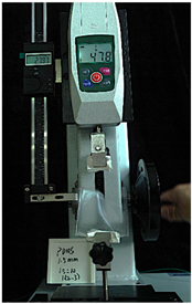 |  |
 |  |  | |
| Silicone | 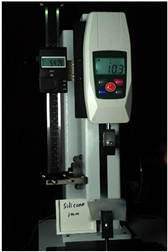 | 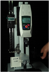 | 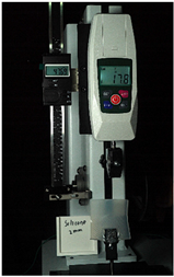 |
 |  |  |
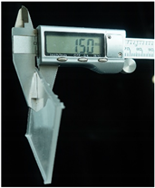
| Thickness (mm) | Initial Length (mm) | Maximum Length (mm) | (%) | |
|---|---|---|---|---|
| PDMS | 1 | 60 | 82.49 | |
| 1.5 | 60 | 87.98 | ||
| 2 | 60 | 86.35 | ||
| Silicone | 1 | 60 | 114.79 | 91.32 |
| 1.5 | 60 | 104.27 | 73.78 | |
| 2 | 60 | 107.69 | 79.48 |
| 1.5:10 | 1:10 | 1:20 |
|---|---|---|
 |  |  |
| Ratio | Initial Length (mm) | Maximum Length (mm) | (%) | |
|---|---|---|---|---|
| PDMS | 1.5:10 | 60 | 87.97 | |
| 1:10 | 60 | 74.92 | ||
| 1:20 | 60 | 77.92 |
| Silver Ink | Electrically Conductive Ink | Silver Wires | |
|---|---|---|---|
| Type | BroadCON-Ink550 | Elasink 990M | -- |
| Color | Silver Gray | Black Gray | Silver |
| Conductivity | |||
| Viscosity | cps | cps | -- |
| Fineness | 60 μm | 3 | |
| Concentration | ≥30 wt% | ≥50 wt% | ≥99.99% |
| Drying conditions | Oven 150 °C/30 min | Oven 150 °C/20 min | -- |
| RP-C7.6-ST | RP-C7-LT | FSR400 | |
|---|---|---|---|
 |  |  | |
| Range | 30 g–1.5 kg | 2 g–1.5 kg | 50 g–2 kg |
| Operating temperature | −20–65 °C | −20–65 °C | −40 °C–85 °C |
| Recovery times | 0.01 s | 0.01 s | 0.01 s |
| Response time | 10 ms | 3 ms | 3 ms |
| Operating voltage | 3.3–5 V DC | 3.3–5 V DC | 3.3–5 V DC |
| Resistance range | 400 Ω–1 MΩ | 100 Ω–10 MΩ | 300 Ω–10 MΩ |
| Weight | 1 g | 1 g | 1 g |
| Dimensions | 14 mm × 32 mm × 1 mm | 44 mm × 7 mm × 0.3 mm | 40 mm × 40 mm × 0.46 mm |
| Durability | ≥1 million cycles | ≥1 million cycles | ≥1 million cycles |
| 1 kg | 2 kg | 3 kg | |
|---|---|---|---|
| RP-C7.6-ST |  | 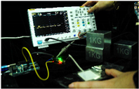 | 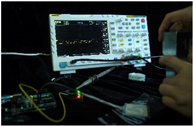 |
 |  |  | |
| RP-C7-LT | 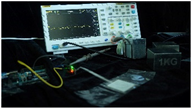 |  |  |
 |  |  | |
| FSR400 |  | 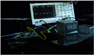 |  |
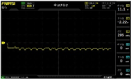 |  |  |
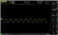
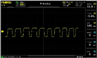
| RP-C7.6-ST with 1 kg | 10 V/div | 5 s/div | 3.33 Hz | 40.4 V | −7.67 V |
| RP-C7.6-ST with 2 kg | 10 V/div | 5 s/div | 3.33 Hz | 40.4 V | −7.67 V |
| RP-C7.6-ST with 3 kg | 10 V/div | 5 s/div | 185 mHz | 5.65 V | −4.84 V |
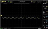
| RP-C7-LT with 1 kg | 10 V/div | 5 s/div | 145 mHz | 11.9 V | −5.85 V |
| RP-C7-LT with 2 kg | 10 V/div | 5 s/div | 145 mHz | 11.9 V | −5.85 V |
| RP-C7-LT with 3 kg | 10 V/div | 5 s/div | 145 mHz | 11.9 V | −5.85 V |
| FSR400 with 1 kg | 10 V/div | 5 s/div | 285 mHz | 11.1 V | −2.22 V |
| FSR400 with 2 kg | 10 V/div | 5 s/div | 285 mHz | 11.1 V | −2.22 V |
| FSR400 with 3 kg | 10 V/div | 5 s/div | 291 mHz | 8.28 V | −4.44 V |
| Flex4.5 | |
|---|---|
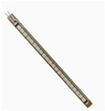 | |
| Dimensions | 112 mm × 6.35 mm × 0.43 mm |
| Operating voltage | 3.3–5 V DC |
| Life cycle | >1 million |
| Flat resistance | 10 K Ohms ± 30% |
| Bend resistance | 60 K–110 K Ohms ± 30% (@ 180° pinch bend) |
| Power rating | 0.5 Watts continuous; 1 Watt Peak |
| Temperature | −35 °C~+80 °C |
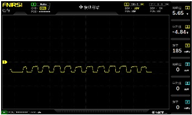
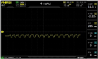
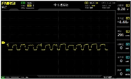
| Test Action | Oscilloscope Signal | |
|---|---|---|
| Slight bending | 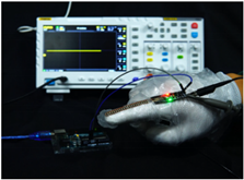 |  |
| Mild bending |  | 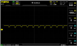 |
| Moderate bending | 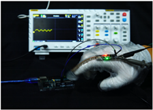 |  |
| Severe bending |  | 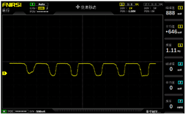 |
| Pulse Sensor | Intelligent Watch | |
|---|---|---|
 |  | |
| Size | 16 mm | 42 mm |
| Power supply | 3.3~5 V | 3.3~5 V |
| Current consumption | ~4 ma | ~300 ma |
| Output signal type | Analog signal | Table data |
| Signal type detected | Photoplethysmography (PPG) | Optical heart rate monitoring and electrocardiogram (ECG) monitoring |
Disclaimer/Publisher’s Note: The statements, opinions and data contained in all publications are solely those of the individual author(s) and contributor(s) and not of MDPI and/or the editor(s). MDPI and/or the editor(s) disclaim responsibility for any injury to people or property resulting from any ideas, methods, instructions or products referred to in the content. |
© 2025 by the authors. Licensee MDPI, Basel, Switzerland. This article is an open access article distributed under the terms and conditions of the Creative Commons Attribution (CC BY) license (https://creativecommons.org/licenses/by/4.0/).
Share and Cite
Luo, C.; Zhang, Y.; Zhang, J.; Hui, L.; Qi, R.; Han, Y.; Sun, X.; Li, Y.; Wei, Y.; Zhang, Y.; et al. Wearable Arduino-Based Electronic Interactive Tattoo: A New Type of High-Tech Humanized Emotional Expression for Electronic Skin. Sensors 2025, 25, 2153. https://doi.org/10.3390/s25072153
Luo C, Zhang Y, Zhang J, Hui L, Qi R, Han Y, Sun X, Li Y, Wei Y, Zhang Y, et al. Wearable Arduino-Based Electronic Interactive Tattoo: A New Type of High-Tech Humanized Emotional Expression for Electronic Skin. Sensors. 2025; 25(7):2153. https://doi.org/10.3390/s25072153
Chicago/Turabian StyleLuo, Chuanwen, Yan Zhang, Juan Zhang, Linyuan Hui, Ruisi Qi, Yuxiang Han, Xiang Sun, Yifan Li, Yufei Wei, Yiwen Zhang, and et al. 2025. "Wearable Arduino-Based Electronic Interactive Tattoo: A New Type of High-Tech Humanized Emotional Expression for Electronic Skin" Sensors 25, no. 7: 2153. https://doi.org/10.3390/s25072153
APA StyleLuo, C., Zhang, Y., Zhang, J., Hui, L., Qi, R., Han, Y., Sun, X., Li, Y., Wei, Y., Zhang, Y., Sun, H., Li, N., & Zhang, B. (2025). Wearable Arduino-Based Electronic Interactive Tattoo: A New Type of High-Tech Humanized Emotional Expression for Electronic Skin. Sensors, 25(7), 2153. https://doi.org/10.3390/s25072153