Article

THRU–REFLECT Method for Scattering Parameter Extraction from Back-to-Back Measurements of Waveguide Components

by
Songyuan Xu
,
Jiwon Heo
,
Chan-Soo Lee
,
Ki-Hong Kim
* and
Bierng-Chearl Ahn
*
School of Electric and Computer Engineering, Chungbuk National University, Cheongju 28644, Republic of Korea
*
Authors to whom correspondence should be addressed.
Sensors 2025, 25(7), 2277; https://doi.org/10.3390/s25072277
Submission received: 6 January 2025 / Revised: 2 April 2025 / Accepted: 3 April 2025 / Published: 3 April 2025

Abstract

:
The design of new waveguide components is often verified by back-to-back measurements of two identically fabricated units without extracting the characteristics of a single device. This paper presents a simple method of extracting the scattering parameters of waveguide components from back-to-back measurements. The proposed method requires only three waveguide mating connections: one for reflection measurement with an offset SHORT and two for transmission measurement with a THRU configuration. A singular condition in the S-parameter extraction equations is derived, and the optimum length of an offset SHORT standard or a reflecting load is determined based on the singularity condition. The numerical simulation of a broadband coax-to-waveguide transition is employed to show the workings of the proposed method.

1. Introduction

The design of new two-port waveguide components is often experimentally verified using back-to-back measurements of two identically fabricated units. The scattering parameters of a two-port fixture or device can be obtained from reflection measurements using three standard loads: SHORT, OPEN, and MATCH [1,2]. When standard loads are not readily available, it is convenient to use two symmetrical or identical devices in a back-to-back configuration. There is a large number of studies that employ back-to-back measurements for the experimental verification of microwave devices. The back-to-back method is very popular for the experimental verification of transitions between different types of transmission lines, such as coaxial-to-waveguide transition and waveguide-to-printed circuit transition [3,4,5,6,7,8,9,10,11,12,13,14,15]. It has been used for other waveguide devices as well [16,17,18]. In the literature, authors often present their results using back-to-back measurements of two symmetric modules, leaving out the task of extracting the measured scattering parameters of a single unit of the designed device. In device characterization using transmission line transitions, it is necessary to extract the scattering parameters of a single transition from back-to-back measurements or from other types of measurements.
In order to extract the scattering parameters of a single transition or device from back-to-back measurements, one can use various calibration or unterminating methods, including the classic TRL (THRU–REFLECT–LINE) method and its variants [19,20,21,22,23,24,25]. They can be used for the characterization of two non-identical back-to-back connected devices, as well as two identical ones. These methods, however, are overkill since there are only three unknowns, S11, S22, and S21, which can be determined by two measurements: a one-port measurement and a two-port measurement that are independent of each other. One may use time–domain-based methods such as the 1x-REFLECT method and the 2x-THRU method for asymmetrical or symmetrical devices in a back-to-back configuration [26,27,28]. They, however, require a vector network analyzer with a large bandwidth along with time–domain measurement software functionality. The device size needs to be large enough for the time–domain separation of the reflections caused by a single device, which is a factor that makes the 2x-THRU method unattractive for millimeter- and sub-millimeter-wave frequencies, as the device size is often too small for time–domain gating [26].
For symmetrical devices measured in a back-to-back configuration, there are two major frequency–domain approaches to calibrating or characterizing a single device: the LINE–REFLECT [29] method and the LINE–LINE method [30]. The LINE measurement means obtaining the two-port scattering parameters of two identical devices with a section of a transmission line with a known transmission coefficient inserted between the two devices. A back-to-back configuration without a line between the two devices is called THRU. The REFLECT procedure refers to a one-port measurement with a reflecting load with a known reflection coefficient, Γ, connected to the port to mate the two devices. A general REFLECT standard includes a matched load (Γ = 0) [31,32].
In waveguide measurements, misalignment in waveguide-to-waveguide connection is a significant contributor to measurement error, especially above millimeter-wave frequencies. Therefore, a procedure that requires fewer waveguide connections is preferable. Here, a connection means one contact between two waveguide transverse planes or flanges. The THRU–REFLECT configuration requires only three flange-mating connections, two for the THRU measurement and one for the REFLECT measurement, while the LINE–LINE method requires four connections. In the THRU–REFLECT method, the REFLECT measurement provides one equation for S-parameter extraction. The THRU measurement yields the remaining two equations necessary for complete S-parameter extraction.
When a two-port device has coaxial and waveguide ports, the scattering parameters of a single unit can be obtained from back-to-back measurements by adding an additional measurement of the reflection coefficient with an offset SHORT connected to the waveguide port [33,34]. The offset SHORT load is the easiest standard to implement in a hollow metal waveguide. It is a perfect standard with a well-defined shorting position with no parasitic effects.
It is the aim of this paper to present a simple method for extracting the scattering parameters of a waveguide component from back-to-back measurements using the THRU–REFLECT method. The method requires only one reflection measurement with an offset SHORT before or after the back-to-back measurement. Although the demonstration of the measurement is shown for a rectangular waveguide device, the proposed method can be applied to the characterization of other types of waveguides, such as circular waveguides, two-wire transmission lines, and printed lines (e.g., coplanar waveguides).
Many sensors include one or more transitions or interfaces, whose characteristics need to be characterized. The concept proposed in this paper can also be applied to the characterization of sensor interfaces as far as they can be formulated in terms of the scattering parameters.
The proposed method, albeit simple, has never been formally applied to back-to-back measurements in the open literature to the best knowledge of the authors. First, we present the equations for scattering parameter extraction from the back-to-back measurements of two symmetrical devices. Then, singularities in the S-parameter extraction equation are investigated, from which a formula for the optimum length of an offset SHORT or a reflecting load is obtained. Next, an example of the application of the proposed method is presented using a transition from a coaxial line to a reduced-height rectangular waveguide. Finally, the conclusions of the paper are drawn.

2. Theory of Scattering Parameter Extraction

Figure 1a shows a signal flow graph representation of a THRU measurement of two symmetric devices in a back-to-back configuration, where a1 and b1 are the incident and reflected waves at Port 1, respectively, while a2 and b2 are those at Port 2, respectively. The scattering parameters of the device are denoted as S11, S21, S22, and S12, where S11 and S21 are the reflection coefficient at Port 1 and the transmission coefficient from Port 1 to Port 2 with Port 2 terminated with a matched load, respectively, and S22 and S12 are the reflection coefficient at Port 2 and the transmission coefficient from Port 2 to Port 1 with Port 1 terminated with a matched load, respectively. The transmission coefficient of the THRU standard is represented by T, which is one in an ideal case. The THRU standard has zero reflection. Figure 1b shows a signal flow graph for the REFLECT measurement of a device terminated with a load with reflection coefficient, Γ. The calibration load in the REFLECT measurement can, in general, arbitrarily include a matched termination (Γ = 0).
The unknown parameters to be determined from the measurements are S11, S22, and S21S12. For reciprocal devices, S21 (=S12) can be derived from S21S12 using rough information on the phase of S21, which can be estimated from the physical dimension of the device. Individual values of S21 and S12 are usually not necessary since they are used in the product form S21S12 in the de-embedding work.
From the THRU measurement shown in Figure 1a, we obtain the following measured scattering parameters from the signal flow graph analysis [35]:
M 11 = b 1 a 1 a 2 = 0 = S 11 + S 21 S 12 T 2 S 22 1 S 22 2 T 2
M 21 = b 2 a 1 a 2 = 0 = S 21 S 12 T 1 S 22 2 T 2
where M11 is the measured reflection coefficient at Port 1 with Port 2 terminated with a matched load, and M21 is the measured transmission coefficient from Port 1 to Port 2 with Port 2 terminated with a matched load. Due to symmetry, we have M22 = M11 and M12 = M21, where M22 is the reflection coefficient at Port 2 with Port 1 terminated with a matched load, and M12 is the transmission coefficient from Port 2 to Port 1 with Port 1 terminated with a matched load. The proposed method is formulated using the scattering parameter instead of the transmission matrix, which is often employed in calibration approaches that use two or more LINE measurements, such as the TRL method or the LRL method [36,37]. In the proposed method, we use only one THRU measurement, and thus, the use of scattering parameters is more convenient.
There are three unknowns (S11, S22, and S21S12) to be determined, while there are only two equations (Equations (1) and (2)). An additional equation can be obtained from the REFLECT measurement shown in Figure 1b. From the REFLECT measurement, we obtain a reflection coefficient provided by
Q 11 = b 1 a 1 = S 11 + S 21 S 12 Γ 1 Γ S 22
We can manipulate Equations (1)–(3) to obtain the following system of linear equations for S11, S22, and ∆.
S 11 + M 21 T S 22 = M 11
M 11 T S 22 T Δ = M 21
S 11 + Γ Q 11 S 22 Γ Δ = Q 11
where
Δ = S 11 S 22 S 12 S 21
Solving Equations (4)–(6) for S22 yields
S 22 = T ( M 11 Q 11 ) + Γ M 21 T Γ ( M 11 Q 11 ) + T M 21
The remaining two knowns, S11 and ∆, can be obtained using
S 11 = M 11 M 21 T S 22
Δ = M 21 / T M 11 S 22
From Equations (8)–(10), we obtain,
S 21 S 12 = S 11 S 22 Δ
For reciprocal devices, the transmission coefficient can be obtained using the following equation.
S 21 = S 12 = ± S 11 S 22
The sign ambiguity in Equation (12) is resolved using rough knowledge of the electrical length of the device.
Calibration Equations (4)–(6) are singular when the determinant of a matrix–equation representation of a system of linear equations (Equations (4)–(6)) is zero. This is the same condition in which the denominator of Equation (8) is zero, viz.,
T Γ ( M 11 Q 11 ) + M 21 T 2 = 0
from which we obtain
T = 0
or
Γ ( Q 11 M 11 ) = M 21 T
Equation (14) is trivial, and we can use Equation (15) to derive a singular condition. We can plug Equations (1)–(3) into Equation (15) to obtain
Γ S 11 + S 21 S 12 Γ 1 Γ S 22 S 11 S 21 S 12 T 2 S 22 1 S 22 2 T 2 = S 21 S 12 T 2 1 S 22 2 T 2
which is simplified to the following equation:
Γ Γ ( 1 S 22 2 T 2 ) T 2 S 22 ( 1 Γ S 22 ) = T 2 ( 1 Γ S 22 )
A further reduction of Equation (17) yields
Γ ( Γ T 2 S 22 ) = T 2 ( 1 Γ S 22 )
from which we obtain the following condition for the singularity.
Γ 2 = T 2 Γ = T   or   Γ = T
Equation (19) is a general relation that applies to any calibration scheme that uses the LINE and REFLECT measurements for two identical devices. The LINE measurement and the REFLECT measurement are no longer independent of each other whenever the condition of Equation (19) is satisfied for arbitrary T and Γ, which is to be avoided for accurate measurements.
Specifically, when T = 1 (a THRU configuration), an OPEN standard (Γ = 1) or a SHORT standard (Γ = −1) cannot be used in the THRU–REFLECT method. Instead, one can use an offset SHORT, which is easy to implement in hollow cylindrical transmission lines such as rectangular and circular waveguides. Two singular points, Γ = ±1, provided by Equation (19) are denoted by × in Figure 2 in the case of the THRU-connected back-to-back measurement (T = 1).
For measurement frequency from f1 to f2, the reflection coefficient of the REFLECT standard, Γ, is set to be equal to Γ1 and Γ2 at frequencies f1 and f2, respectively, as shown in Figure 2, where Γ1 and Γ2 are provided by
Γ 1 = e j θ 0 = e j ( π θ 0 ) ( f = f 1 )
Γ 2 = e j ( π θ 0 ) = e j θ 0 ( f = f 2 )
For accurate measurements, a minimum value of the angular distance, θ0, of the reflection coefficient of the REFLECT standard from the singularities of the THRU measurement ranges from 10° to 30° [38].
Let the waveguide length of the offset SHORT be L. Then, the input reflection coefficient of the offset SHORT is provided by
Γ = e j θ = e j ( π θ )
where θ is the two-way phase shift in the waveguide of length L, which is provided by
θ = 4 π L λ g
where λg is the wavelength in the waveguide provided by
λ g = c f 2 f c 2
where c is the speed of light in the material that fills the waveguide, and fc is the cutoff frequency of the propagating mode in the waveguide. For the rectangular waveguide TE10 mode, fc is provided by c/(2a), where a is the width of the broad wall. It is important to note that only a single mode should propagate in the waveguide since all of the quantities we have mentioned (S11, S21, S21S12, T, and Γ) are defined for a single propagating mode, which is usually the lowest-order dominant mode.
The optimum length of the offset SHORT can now be obtained as follows. For f1ff2, we require
θ 0 θ π θ 0
from which we obtain
θ 0 = 4 π L λ g 1 & π θ 0 = 4 π L λ g 2
Finally, from Equation (26), we obtain
L = λ g 1 λ g 2 4 ( λ g 1 + λ g 2 )
In the next section, we will present an example of the application of the proposed method using the numerical simulation of a back-to-back configuration of two coaxial-to-waveguide adapters.

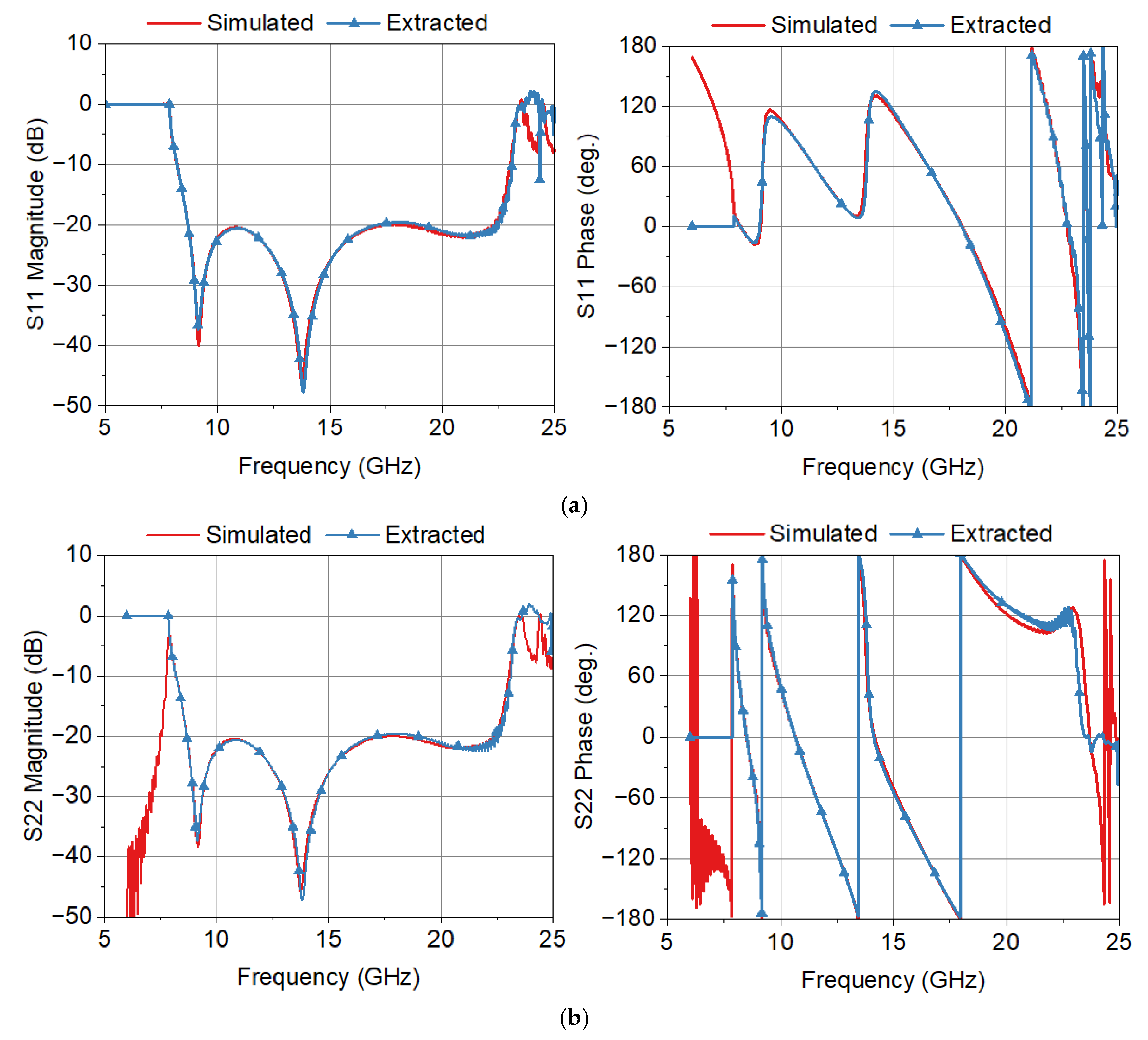
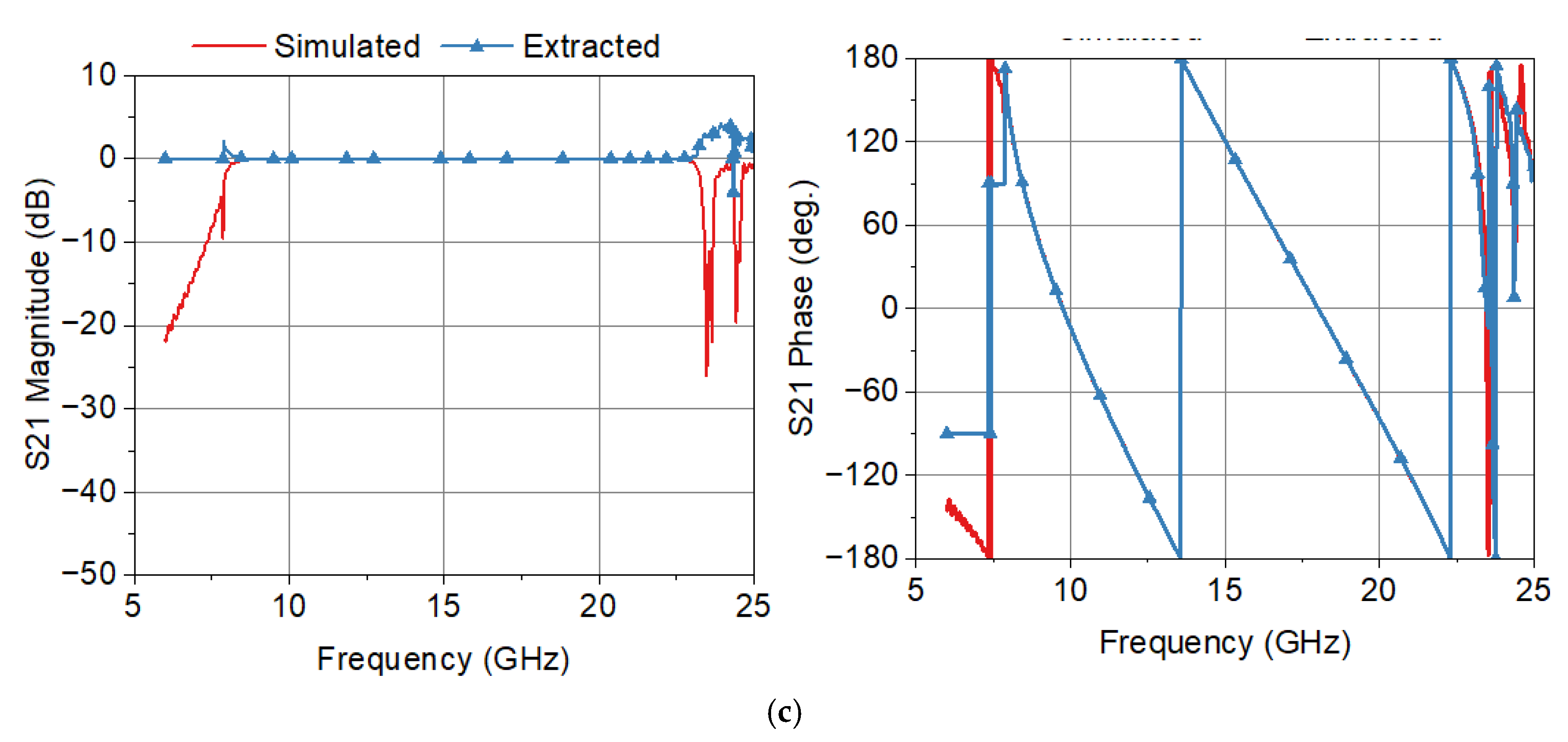
3. Example of Scattering Parameter Extraction

In this section, an example is presented for the THRU–REFLECT method of scattering parameter extraction based on the theory described in Section 2. M11 and M21 (Equations (1) and (2)) from the THRU measurement and Q11 (Equation (3)) from the REFLECT measurement are obtained by the numerical simulation of respective structures. Any numerical simulation has finite accuracy so that it can mimic actual measurements. The widely used CST Studio SuiteTM V. 2022 is used for the simulation.
To show the workings of the proposed method, we use a coaxial-to-reduced-height rectangular waveguide transition, shown in Figure 3. The transition consists of a coaxial probe and a tuning post, all of which are positioned in the waveguide center line. With centered symmetric structures and the excitation of the even-symmetric field of the TE10 mode, the TE20 mode with its odd-symmetric field is not excited. The transition is of a very wideband design, which is made possible by reducing the waveguide height, b, so that the cutoff frequencies of the TE11 and TE30 modes coincide with each other, which is satisfied when b = a/√8 = 0.354a [39], where a and b are the width of the broad and narrow walls of the rectangular waveguide. Therefore, the transition can operate from the cutoff frequency of the dominant TE10 mode to that of the TE11 and TE30 modes. We use the broad wall width a = 19.05 mm (the WR-75 standard waveguide) and the narrow wall height b = 6.74 mm in our example so that the transition can operate from 7.87 GHz to 23.62 GHz. The transition has been designed so that its bandwidth is as large as possible.
Figure 4 shows the simulated TE10 mode reflection coefficient and higher-order mode transmission coefficients of the transition. The reflection coefficient corresponds to S11 of the transition, which needs to be extracted by the THRU–REFLECT method. In Figure 4, we can observe that the transition’s reflection coefficient is less than −20 dB at 8.65–22.31 GHz. Above 22.31 GHz, the reflection coefficient of the TE10 mode and the transmission coefficients of higher-order TE11, TE30, and TM11 modes increase rapidly.
Figure 5a shows two identical transitions joined in a back-to-back configuration and Figure 5b shows their TE10 mode reflection and transmission coefficients, which correspond to the magnitudes of M11 and M21 provided by Equations (1) and (2), respectively. In order to extract the scattering parameters (S11, S22, and S21) of the transition, we need the phase information as well, and it will be determined when we compare the extracted scattering parameters with the simulated ones.
Comparing Figure 4 with Figure 5b, we note that the reflection coefficient of the transition in a back-to-back configuration is significantly different from that of a single transition and that the back-to-back measured values can hardly represent the performance of the designed transition shown in Figure 4. Due to multiple reflections between two transitions, more local maxima and minima appear in the reflection coefficient curve. The maximum reflection coefficient is increased from −20 dB to −16.3 dB in the operating frequency range of the transition.
Figure 6 shows the configurations for the offset SHORT and the THRU or back-to-back measurements. Figure 6a is the structure for a measurement with an offset SHORT, while Figure 6b shows a configuration for a THRU measurement. First, we make a measurement with an offset SHORT through numerical simulation using CST Studio SuiteTM V. 2022. The length of the offset SHORT is determined to be 3.10 mm for a frequency range of 8–24 GHz according to Equation (27). With an offset SHORT length of 3.10 mm, the two-way phase delay is 10.5° at 8 GHz and 168.8° at 24 GHz. The reflection coefficient, Q11, of the offset SHORT measurement is obtained through the numerical simulation of the structure of Figure 6a. Simulation is performed at 1001 frequency points from 6 GHz to 25 GHz.
Next, we make a measurement of the transition with a THRU connection. The reflection coefficient, M11, and the transmission coefficient, M21, are simulated using the back-to-back configuration of Figure 6b. The values of M11 and M21 are obtained at 1001 frequency points from 6 GHz to 25 GHz. A code has been written to read the numerical data of the magnitudes and phases of M11, M21, and Q11 obtained by the simulation and to extract the scattering parameters of a single transition using the equations presented in Section 2.
Figure 7 shows a comparison of the simulated and extracted scattering parameters of a single transition. Data for frequencies less than the cutoff frequency (7.87 GHz) of the waveguide are not valid and are used only for graphing purposes. We note in Figure 7 that the agreements between the simulated and extracted scattering parameters are excellent. As the frequency approaches the cutoff frequency of the TE11 and TE30 modes, there are some noticeable errors in the extracted scattering parameters. This can be attributed to the increased levels of higher-order modes generated in the transition.
The proposed method yields accurate results at frequencies where only the dominant mode can propagate. In order to include the effects of the higher-order modes and, thus, to increase the frequency range of device characterization, an advanced method proposed in [40] can be used, where the same calibration standards as the ones used in this paper are employed, but a sophisticated nontermination algorithm is used that employs the generalized scattering matrix (GSM) and the genetic algorithm–gradient descent (GA-GD) method-based optimization technique.
For a device that employs higher modes and a dominant mode, structures for extracting specific modes are prepared, and measurements are made for a combination of modes, as well as for specific modes. To extract the device characteristics, the generalized scattering matrix is used, which includes interactions between all of the modes present in the device [41].
Table 1 shows numerical values used for the S-parameter extraction at 10, 15, and 20 GHz, along with the extracted scattering parameters of a single transition. The difference between the actual and extracted magnitudes of S11 and S22 is less than 0.6 dB. The maximum phase difference in the phases of S11 and S22 is less than 10°. Errors in the phases of S11 and of S22 are increased when the magnitudes of S11 and S22 are small, for example, less than −30 dB. Agreements in the magnitude and phase of S21 are excellent. This is due to the fact that the magnitude of S21 is close to 0 dB.
Table 2 shows error statistics for the scattering parameter extraction. The difference represents the extracted value minus the simulated value. The standard deviation is less than 0.7 dB in the magnitudes of S11 and S22, while it is less than 4.5° in the phases of S11 and S22. Large phase errors in S11 and S22 at 9.12 GHz and at 13.77 GHz are due to the smallness of the magnitude of S11 and S22. Agreement in S21 is excellent, with the standard deviation of the magnitude and phase of S21 being 0.18 dB and 0.077°, respectively. Error in S21 is increased as the frequency approaches the cutoff frequency (7.87 GHz).
Figure 7 and Table 1 and Table 2 show that the proposed THRU–REFLECT method offers an accurate approach to extracting the scattering parameters of a single device from a back-to-back measurement of waveguide components for a 3:1 bandwidth with one offset SHORT measurement and one THRU measurement. With a simple modification, the proposed method can be applied to the back-to-back measurements of other types of microwave devices. For example, the proposed method can be applied to microstrip devices using an offset SHORT or OPEN standard for the REFLECT measurement.
In Table 3, the proposed method is compared with other methods applicable to the characterization of back-to-back connected devices. The THRU–LINE method [42] and the THRU–MATCH method [43] are more complicated than the proposed method. The former requires four flange connections, while the latter uses a matched termination, which is costly to realize. The THRU-Only method [44] is simpler than the proposed method since it requires only a THRU connection or a back-to-back connection and one two-port measurement. However, its applicability is limited since the condition S11 = S22 is assumed. The 2x-THRU method [45] is widely used and implemented in high-end vector network analyzers (VNAs), referred to as AFR (Automatic Fixture Removal). It uses a LINE standard that is long enough for the time–domain separation of a short impulse signal. It requires time–domain gating software functionality, as well as a broadband (e.g., from 10 MHz to 50 GHz) VNA. Thus, the 2x-THRU method is useful only for device measurements using high-end VNAs.
The advantage of the proposed method lies in the fact that it requires a simple offset short, which is easy to implement in a waveguide, and that only three flange connections are made during measurements. The algorithm of the proposed method is simple, and it can be compactly implemented in low-end VNAs.

4. Conclusions

A full and comprehensive treatment has been presented for the THRU–REFLECT method for scattering parameter extraction from a back-to-back measurement of waveguide components. It has been shown that the scattering parameters of a single device can conveniently be obtained from a back-to-back measurement of two identical waveguide devices using the THRU–REFLECT method, which includes a reflection coefficient measurement with an offset SHORT before or after a THRU measurement. The singularity condition has been derived for a general LINE–REFLECT measurement. The optimum length of an offset SHORT or a reflecting load has been provided in terms of the guided wavelength at the start and end frequencies of the measurement. The workings of the proposed method have been shown by the numerical simulation of a broadband coaxial-to-reduced waveguide transition. It has been shown that with an offset SHORT of optimum length, the scattering parameters of a single device can be accurately extracted from back-to-back measurements over a 3:1 frequency range in the case of a reduced-height rectangular waveguide. Using the proposed method, the general practice in the microwave community of validating new waveguide devices with back-to-back measurements can now be upgraded to include the extraction of the scattering parameters of a single device in a simple and economical way. Areas of additional research include the analysis of measurement uncertainty due to the imperfect mating of waveguides and the application of the proposed method to the back-to-back measurements of other types of microwave devices.

Author Contributions

Conceptualization, S.X.; methodology, S.X. and J.H.; validation, J.H. and C.-S.L.; formal analysis, K.-H.K.; invest, C.-S.L. and K.-H.K.; writing—original draft, K.-H.K. and S.X.; writing—review and editing, B.-C.A.; supervision, B.-C.A.; All authors have read and agreed to the published version of the manuscript.

Funding

This work was supported by the Innovative Human Resource Development for Local Intellectualization Program through the Institute of Information and Communications Technology Planning and Evaluation (IITP) Grant funded by the Korean Government (MSIT) (IITP-2025-RS-2020-II201462).

Institutional Review Board Statement

Not applicable.

Informed Consent Statement

Not applicable.

Data Availability Statement

The data presented in this study are available in this article.

Conflicts of Interest

The authors declare no conflicts of interest.

References

  1. Wu, K.; Li, H.; Li, B.; Zhu, L. Short-open-load (SOL) calibration technique for accurate parameter extraction in micro-coaxial-line circuit. In Proceedings of the 2022 International Conference on Microwave and Millimeter Wave Technology (ICMMT), Harbin, China, 12–15 August 2022. [Google Scholar]
  2. Nazrin, M.; Hashim, S.J.; Rokhani, F.Z.; Ali, B.M.; Yusoff, Z. Error correction and uncertainty measurement of short-open-load calibration standards on a new concept of software defined instrumentation for microwave network analysis. J. Meas. Eng. 2019, 7, 107–118. [Google Scholar]
  3. Kim, Y.-G.; Kim, K.W.; Cho, Y.-K. An ultra-wideband microstrip-to-CPW transition. In The analysis of circular waveguide phased arrays. In Proceedings of the 2008 IEEE MTT-S International Microwave Symposium Digest, Atlanta, GA, USA, 15–20 June 2008. [Google Scholar]
  4. Li, G.M.; Li, Q. The design of Ka band waveguide-to-microstrip transition. In Proceedings of the International Conference on Computational Problem-Solving (ICCP), Chengdu, China, 21–23 October 2011. [Google Scholar]
  5. Nghia, N.-T.; Kaufmann, T.; Fumeaux, C. Wideband transition from coaxial cable to half-mode substrate integrated waveguide. In Proceedings of the 2013 Asia-Pacific Microwave Conference (APMC), Seoul, Republic of Korea, 5–8 November 2013. [Google Scholar]
  6. Shams, S.I.; Kish, A.A. Waveguide coaxial to ridge gap waveguide transition. IEEE Trans. Microw. Theory Tech. 2016, 64, 4117–4125. [Google Scholar]
  7. Cano, J.L.; Mediavilla, A. Octave bandwidth in-line rectangular waveguide-to-coaxial transition using oversized mode convers. Electron. Lett. 2017, 53, 1370–1371. [Google Scholar]
  8. Dong, Y.; Johansen, T.K.; Zhurbenko, V.; Hanberg, P.J. A rectangular waveguide-to-coplanar waveguide transition at D-band using wideband patch antenna. In Proceedings of the 46th European Microwave Conference (EuMC), Madrid, Spain, 23–27 September 2018. [Google Scholar]
  9. Herraiz, D.; Esteban, H.; Martínez, J.A.; Belenguer, A.; Cogollos, S.; Nova, V.; Boria, V.E. Transition from microstrip line to ridge empty substrate integrated waveguide based on the equations of the superellipse. Appl. Sci. 2020, 10, 8101. [Google Scholar] [CrossRef]
  10. Liu, Z.; Cheng, X.; Yao, Y.; Yu, T.; Yu, J.; Chen, X. Broadband transition from rectangular waveguide to groove gap waveguide for mm-wave contactless connections. Electronics 2020, 9, 1820. [Google Scholar] [CrossRef]
  11. Pérez, J.A.G.; Goussetis, G.; Fan, H.; Ding, Y. A low-loss Ka-band waveguide to substrate integrated waveguide transition based on ridged stepped-impedance transformer. Electron. Lett. 2021, 57, 662–664. [Google Scholar]
  12. Xu, Q.; Jiang, Z.; Guo, C. A design of waveguide-to-microstrip transition for V-band device testing. In Proceedings of the 2022 International Conference Microwave Millimeter Wave Technology (ICMMT), Harbin, China, 12–15 August 2022. [Google Scholar]
  13. Pittermann, M.; Zwick, T.; Bhutani, A. A 53–125 GHz chip to double-ridge rectangular waveguide transition. Electron. Lett. 2024, 60, 1–4. [Google Scholar]
  14. Kim, H.; Kim, G.; Cho, J.; Park, K.; Kim, S. Design of wideband right-angle CPWG-to-waveguide transition for Ku-band application. IEEE Microw. Wireless Comp. Lett. 2024, 34, 149–152. [Google Scholar]
  15. Lee, Y.-C.; Wang, C.-L. Compact and broadband rectangular waveguide-to-circular waveguide transition. In Proceedings of the 2024 IEEE 4th International Conference Electronic Communications Internet Things & Big Data (ICEIB), Taipei, Taiwan, 19–21 April 2024. [Google Scholar]
  16. Sorokosz, L.; Zieniutycz, W. Estimation of a single balun parameters on the base of back-to-back measurements. In Proceedings of the 2016 21st International Conference Microwave, Radar and Wireless Communications (MIKON), Krakow, Poland, 9–11 May 2016. [Google Scholar]
  17. Chang, W.-C.; Wunsch, G.J.; Schaubert, D.H. Back-to-back measurement for characterization of phased-array antennas. IEEE Trans. Antennas Propagat. 2000, 48, 1079–1085. [Google Scholar]
  18. Pittermann, M.; Zwick, T.; Bhutani, A. A DC to 125 GHz probe pad design. In Proceedings of the 54th European Microwave Conference, Paris, France, 24–26 September 2024. [Google Scholar]
  19. Silvonen, K.J. Calibration of test fixtures using at least two standards. IEEE Trans. Microw. Theory Tech. 1991, 39, 624–630. [Google Scholar]
  20. Silvonen, K.J. A general approach to network analyzer calibration. IEEE Trans. Microw. Theory Tech. 1992, 40, 754–759. [Google Scholar]
  21. Zúňiga-Juárez, J.E.; Reynoso-Hernández, J.A.; Loo-Yau, J.R.; Maya-Sánchez, M.C. An improved two-tier L-L method for characterizing symmetrical microwave test fixtures. Measurements 2011, 44, 1491–1498. [Google Scholar]
  22. Stephens, D.; Young, P.R.; Robertson, I.D. Millimeter-wave substrate integrated waveguides and filters in photoimageable thick-film technology. IEEE Trans. Microw. Theory Tech. 2005, 53, 3832–3838. [Google Scholar]
  23. Kang, T.-G.; Park, J.-K.; Kim, B.-H.; Lee, J.J.; Choi, H.H.; Lee, H.-J.; Yook, J.-G. Microwave characterization of conducting polymer PEDOT: PPS film using a microstrip line for humidity sensor application. Measurements 2019, 137, 272–277. [Google Scholar]
  24. Liu, Z.; Xu, J.; Wang, W. Wideband transition from microstrip line-to-empty substrate-integrated waveguide without sharp dielectric taper. IEEE Microw. Wireless Comp. Lett. 2019, 29, 20–22. [Google Scholar]
  25. Rho, J.-E.; Li, J.-W.; Ahn, B.-C.; Park, C.-S.; Cha, E.-J. Novel approach to optimizing a broadband right-angle coaxial-to-microstrip transition. Microw. Opt. Technol. Lett. 2007, 49, 451–456. [Google Scholar]
  26. Moon, S.-J.; Ye, X.; Smith, R. Comparison of TRL calibration vs. 2x thru de-embedding methods. In Proceedings of the 2015 IEEE Symposium on Electromagnetic Compatibility and Signal Integrity, Santa Clara, CA, USA, 15–21 March 2015. [Google Scholar]
  27. Chen, Y.; Chen, B.; He, J.; Zai, R.; Fan, J.; Drewniak, J. De-embedding comparisons of 1x-reflect SFD, 1-port AFR, and 2x-thru SFD. In Proceedings of the 2018 IEEE International Symposium on Electromagnetic Compatibility and 2018 IEEE Asia-Pacific Symposium on Electromagnetic Compatibility, Suntec City, Singapore, 14–18 May 2018. [Google Scholar]
  28. Ellison, J.; Smith, S.B.; Agili, S. Using a 2x-thru standard to achieve accurate de-embedding of measurements. Microw. Opt. Technol. Lett. 2020, 62, 675–682. [Google Scholar]
  29. Simion, S. A new unterminating method for de-embedding the coaxial to waveguide transitions. Prog. Electromagn. Res. C 2022, 121, 255–264. [Google Scholar]
  30. Torres-Torres, R.; Hernández-Sosa, G.; Romo, G.; Sánchez, A. Characterization of electrical transitions using transmission line measurements. IEEE Trans. Adv. Packag. 2009, 32, 45–52. [Google Scholar]
  31. Han, X.; Zhu, W.; Yang, Q. An embedded auto-calibration approach used in one-port calibration of VNA. In Proceedings of the 11th IEEE International Conference on Electronic Measurement Instruments, Harbin, China, 16–19 August 2013. [Google Scholar]
  32. Ou, J.; Caggiano, M.F. Determine two-port S-parameters from one-port measurements using calibration substrate standards. In Proceedings of the 2005 Electronic Components and Technology (ECTC ’05), Lake Buena Vista, FL, USA, 20 June 2005. [Google Scholar]
  33. Scalzi, G.J.; Slobodnik, A.J., Jr.; Roberts, G.A. Network analyzer calibration using offset shorts. IEEE Trans. Microw. Theory Tech. 1988, 36, 1097–1100. [Google Scholar]
  34. Horibe, M.; Kishikawa, R. Improvement of offset short calibration technique in waveguide VNA measurement at millimeter and sub-millimeter wave frequency. In Proceedings of the 29th Conference on Precision Electromagnetic Measurements (CPEM 2014), Rio de Janeiro, Brazil, 24–29 August 2014. [Google Scholar]
  35. Hunton, J.K. Analysis of microwave measurement techniques by means of signal flow graphs. IRE Trans. Microw. Theory Tech. 1960, 8, 206–212. [Google Scholar]
  36. Buff, P.M.; Nath, J.; Steer, M.B. Origin of the half-wavelength errors in microwave measurements using through−line calibrations. IEEE Trans. Instrum. Meas. 2007, 56, 1610–1615. [Google Scholar]
  37. Fuh, K.-F. Formulation for propagation factor extractions in thru-reflect-line/line-reflect-line calibrations and related applications. IEEE Trans. Microw. Theory Tech. 2016, 64, 1594–1606. [Google Scholar]
  38. Marks, R.B. A multiline method of network analyzer calibration. IEEE Trans. Microw. Theory Tech. 1991, 39, 1205–1215. [Google Scholar]
  39. Zhang, Q.; Xu, X.; Heo, J.; Atlanzaya, E.; Ariunbold, G.-Y.; Otgonbat, D.; Lee, C.-S.; Ahn, B.-C.; Li, S.; Choi, S.-G. Computational design of a broadband in-line coaxial-to-rectangular waveguide transition. Appl. Sci. 2023, 14, 74. [Google Scholar] [CrossRef]
  40. Lozano-Guerrero, A.J.; Monzó-Cabrera, J.; Pitarch, J.; Clemente-Fernández, F.J.; Fayos-Fernández, J.; Pedreño-Molina, J.L.; Matínez-González, A.; Díaz-Morcillo, A. Multimodal retrieval of the scattering parameters of a coaxial-to-waveguide transition. IEEE Trans. Microw. Theory Tech. 2021, 69, 5241–5249. [Google Scholar]
  41. Panzner, B.; Jöstingmeier, A.; Omar, A. A novel multimodal waveguide technique for the broadband characterization of dielectric material parameters. In Proceedings of the 42nd European Microwave Conference, Amsterdam, The Netherlands, 29 October–1 November 2012. [Google Scholar]
  42. Eccleston, K.W. A new interpretation of through-line deembedding. IEEE Trans. Microw. Theory Tech. 2016, 64, 3887–3893. [Google Scholar]
  43. Ehlers, E.R. Symmetric text fixture calibration. In Proceedings of the 1986 IEEE MTT-S International Microwave Symposium, Baltimore, MD, USA, 2−4 June 1986. [Google Scholar]
  44. Daniel, E.S.; Harff, N.E.; Sokolov, V.; Schreiber, S.M.; Gilbert, B.K. Network analyzer measurement de-embedding utilizing a distributed transmission matrix bisection of a single THRU structure. In Proceedings of the ARFTG 63rd Conference, Fort Worth, TX, USA, 11 June 2004. [Google Scholar]
  45. Gronau, G.; Wolff, I. A simple broad-band device de-embedding method using an automatic network analyzer with time-domain option. IEEE Trans. Microw. Theory Tech. 1989, 37, 479–483. [Google Scholar]
Figure 1. Signal flow graph for the THRU measurement (a) and for the REFLECT measurement (b).
Sensors 25 02277 g001
Figure 2. Singularities in scattering parameter extraction and the reflection coefficient of the offset SHORT with T =1.
Sensors 25 02277 g002
Figure 3. Coaxial-to-reduced-height rectangular waveguide transition as an example of scattering parameter extraction from back-to-back measurements. Various views are presented to aid in the understanding of the transition.
Sensors 25 02277 g003
Figure 4. Reflection and transmission coefficients of the coaxial-to-waveguide transition.
Sensors 25 02277 g004
Figure 5. (a) Two identical coaxial-to-waveguide transitions in a back-to-back configuration and (b) their reflection (in red) and transmission (in green) coefficients.
Sensors 25 02277 g005
Figure 6. Configurations for (a) an offset SHORT measurement and (b) a THRU or back-to-back measurement.
Sensors 25 02277 g006
Figure 7. Comparison of the simulated and extracted scattering parameters of the transition. (a) S11, (b) S22, and (c) S21.
Sensors 25 02277 g007aSensors 25 02277 g007b
Table 1. Input data for and results of the S-parameter extraction.
Quantities
(Units: dB, deg.)
Frequency (GHz)
101520
Mag./Phase of M11−18.86/61.84−21.84/150.14−17.35/−68.80
Mag./Phase of M21−0.0561/−28.08−0.0293/−119.67−0.0837−159.54
Mag./Phase of Q11−0.0002/105.18−0.0000/−31.700.0019/−114.84
Mag./Phase of T0/00/00/0
Mag./Phase of Γ0/133.950/84.870/43.08
Mag./Phase of S11,
Simulated
−22.05/105.16−26.00/118.83−21.60/−100.42
Mag./Phase of S11,
Extracted
−22.37/102.98−26.09/115.10−21.02/−107.66
Mag./Phase of S22,
Simulated
−22.04/46.00−26.02/−51.19−21.54/121.47
Mag./Phase of S22,
Extracted
−22.36/48.53−26.10/−54.91−21.15/130.76
Mag./Phase of S21,
Simulated
−0.0402/−14.17−0.0247/120.23−0.0428/−79.69
Mag./Phase of S21,
Extracted
0.0255/−14.210.0103/120.230.0308/−79.53
Table 2. Error statistics in the S-parameter extraction.
DifferencesAverageStandard
Deviation
Max./Freq. (GHz)Min./Freq. (GHz)
In Mag. of S11 (dB)0.00880.633.28/9.17−3.50/13.85
In Phase of S11 (deg.)−1.774.3412.32/9.14−31.16/13.77
In Mag. of S22 (dB)0.00980.692.38/13.66−4.19/13.90
In Phase of S22 (deg.)2.184.3438.03/13.77−25.56/9.12
In Mag. of S21 (dB)0.00930.182.19/8.010.0011/9.06
In Phase of S21 (deg.)0.0400.0770.57/8.09−0.61/8.033
Table 3. Comparison of the methods applicable to device characterization in a back-to-back configuration.
MethodsNumber of
Interface
Connections
Number of
Calibration
Standards
Applicable to
Asymmetric
Devices?
Features
THRU-LINE
[42]
41No
  • Two 2-port measurements.
  • One LINE standard required.
  • Complexity: medium.
THRU-MATCH
[43]
31No
  • One 2-port measurement and one 1-port measurement.
  • MATCH standard is costly.
  • Complexity: high.
THRU-Only
[44]
20No
  • One 2-port measurement.
  • Assumption: S11 = S22 (Limited applications).
  • Complexity: low.
2x-THRU
[45]
21Yes
  • Time–domain gating used.
  • One long LINE standard used.
  • Complexity: hardware = low; software = high
Proposed
Method
31No
  • One 1-port measurement and one 2-port measurement.
  • Offset SHORT standard required.
  • Complexity: low.
Disclaimer/Publisher’s Note: The statements, opinions and data contained in all publications are solely those of the individual author(s) and contributor(s) and not of MDPI and/or the editor(s). MDPI and/or the editor(s) disclaim responsibility for any injury to people or property resulting from any ideas, methods, instructions or products referred to in the content.

