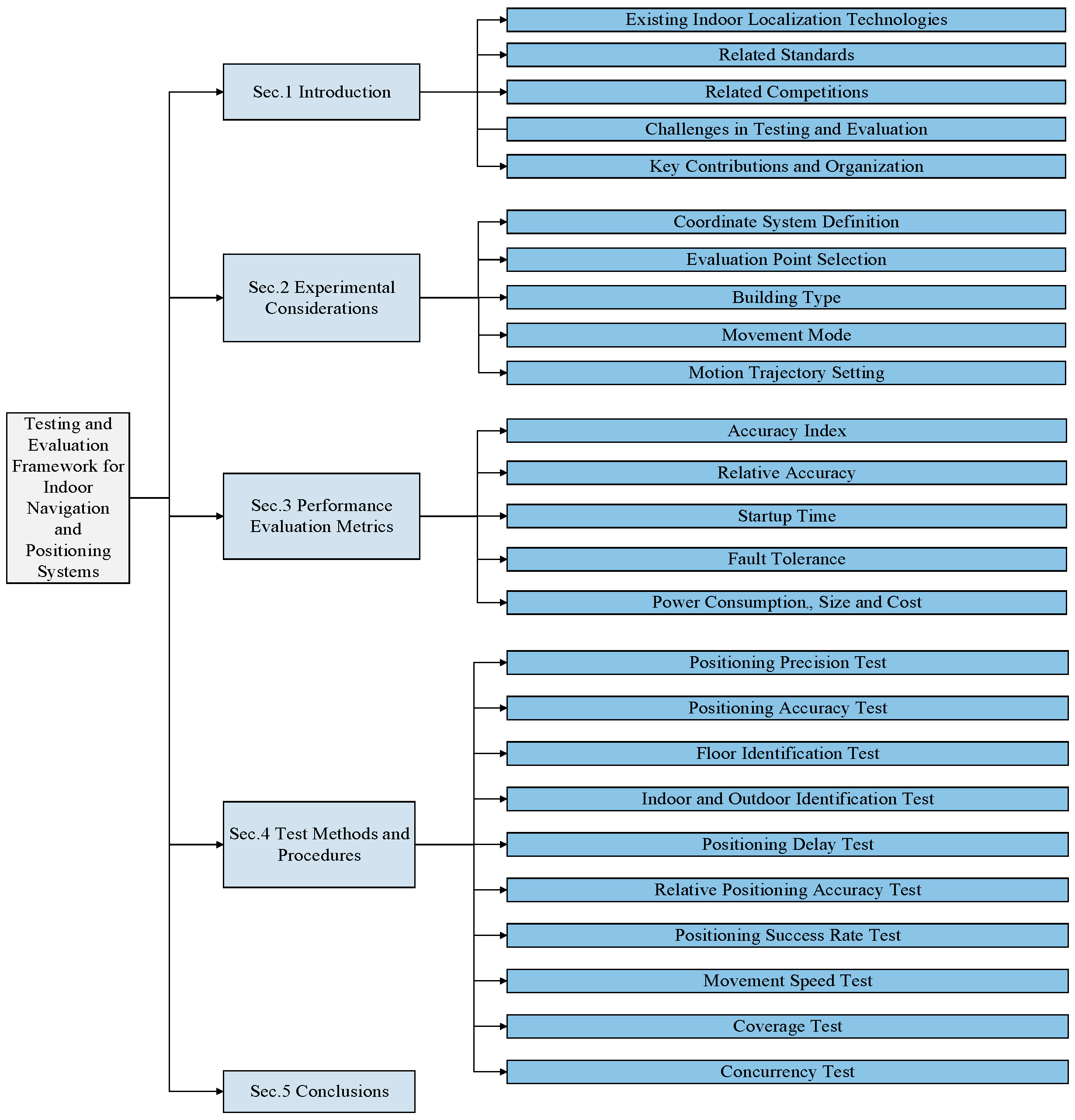
A Testing and Evaluation Framework for Indoor Navigation and Positioning Systems


Abstract
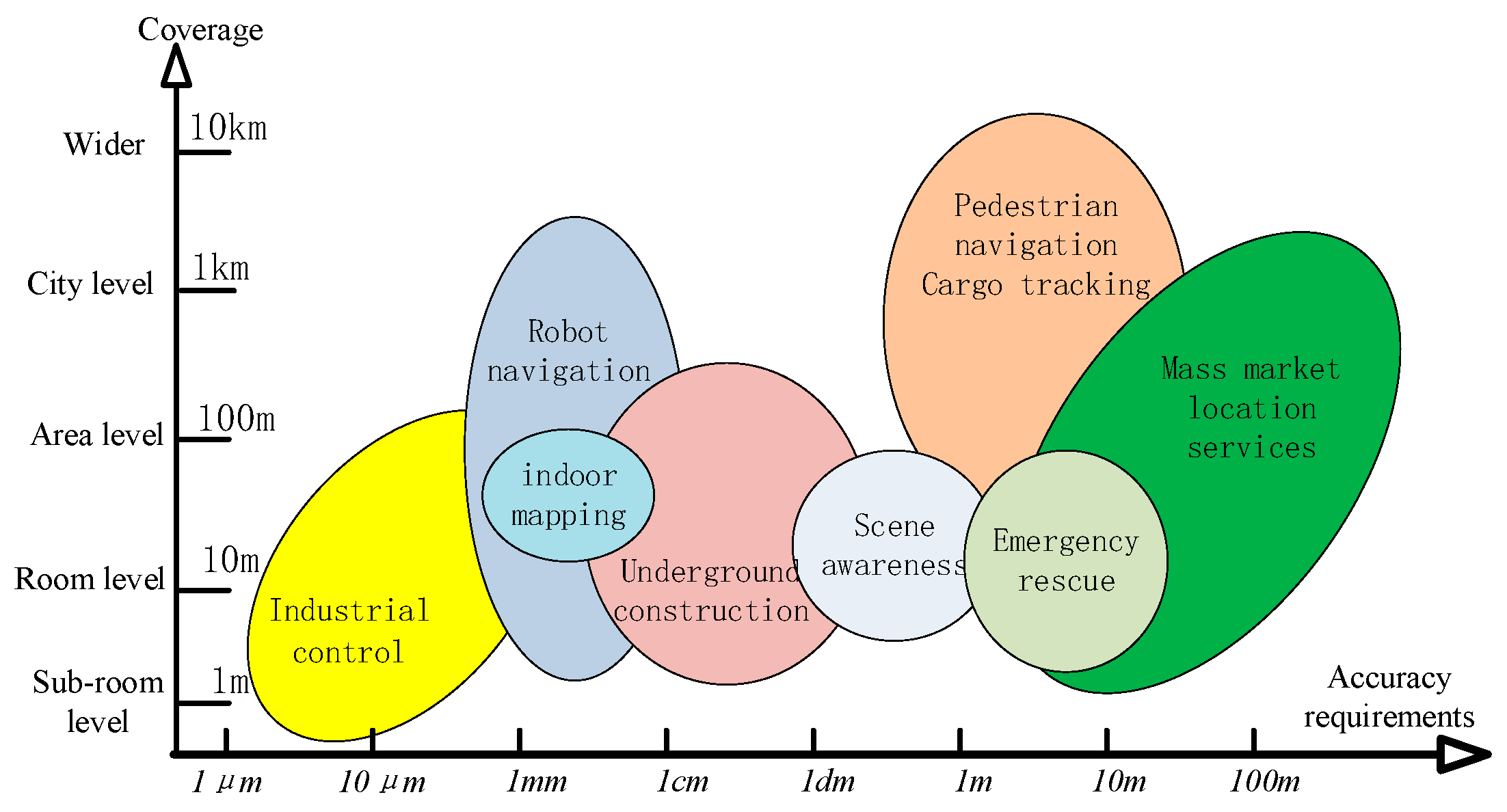
1. Introduction
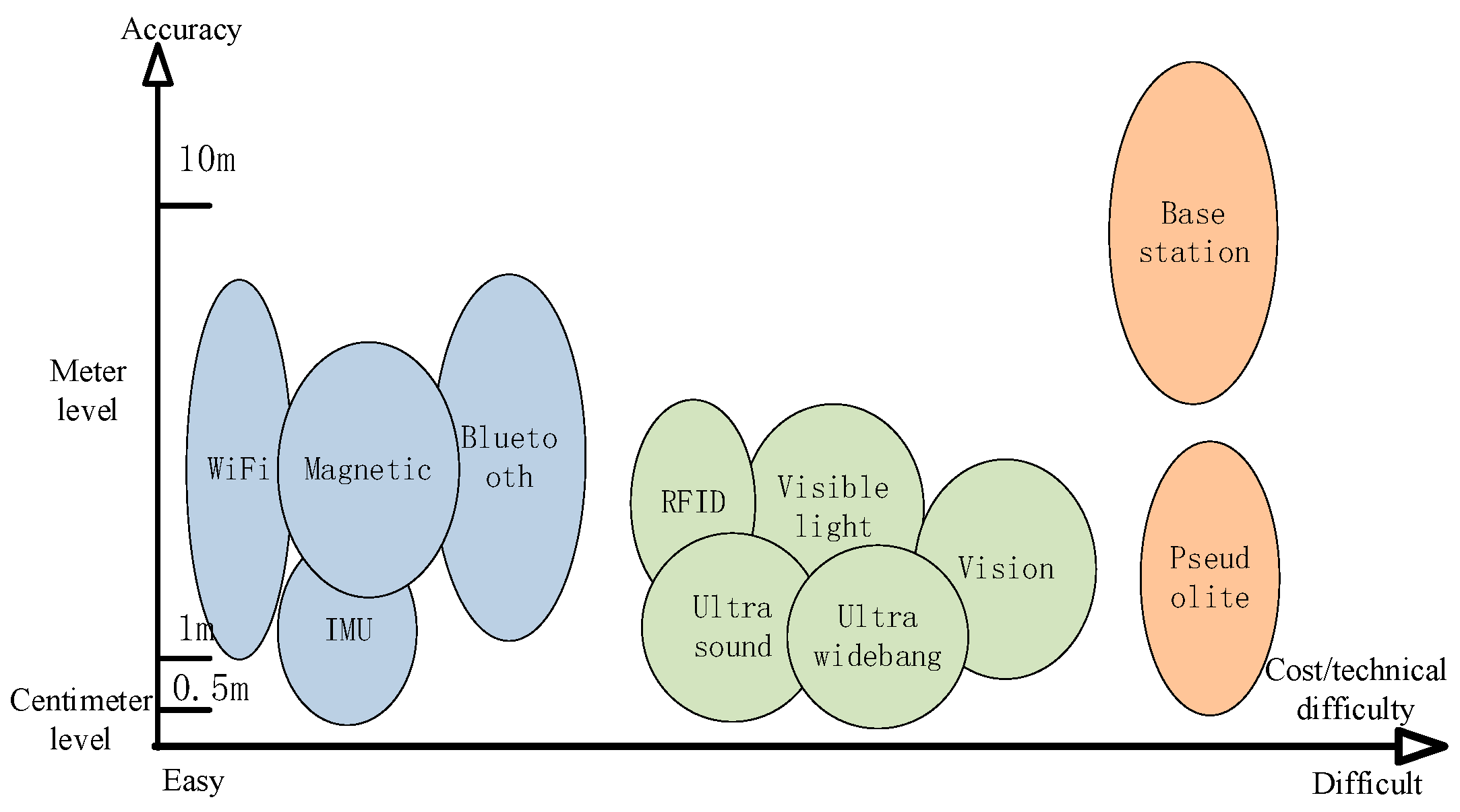
1.1. Existing Indoor Localization Technologies
1.2. Related Standards
- ISO/IEC 18305:2016 [87] is a RTLS performance testing and evaluation standard jointly developed by the International Organization for Standardization (ISO) and the International Electrotechnical Commission (IEC). The standard clarifies the test environment, data collection methods, and evaluation process and standardizes key performance indicators, such as the positioning accuracy, response time, stability, and equipment interoperability requirements of the RTLS. However, ISO/IEC 18305 is not applicable to developers or researchers [88].
- ISO/IEC 24730-1:2014 [89] allows application software to utilize real-time location system (RTLS) infrastructures for monitoring individuals or items equipped with RTLS transmitters.
- ISO 19116:2019 [90] outlines the data format and communication protocol for devices that provide and utilize positional information. It proves beneficial in numerous location-centric applications, including navigation, surveying, and location-based services.
- Bluetooth Core Specification version 5.1 [93] introduces a new direction-finding feature. This capability allows Bluetooth gadgets to achieve precision within centimeters.
- The Wi-Fi Round Trip Time (RTT) [94] feature is a positioning technology based on the IEEE 802.11 mc protocol. It calculates the distance by accurately measuring the signal RTT between the device and the Wi-Fi access point to achieve sub-meter positioning. Wi-Fi RTT has the advantages of requiring no additional hardware, supporting multi-access point co-location, not relying on signal strength (RSSI), a stronger anti-interference ability, and good privacy.
- 3GPP Release 13 [95] demonstrated the capability of LTE to fulfill certain indoor positioning requirements and proposed potential improvements. Key enhancements have been formalized in the recently completed 3GPP Release 16 and 17 projects.
1.3. Related Competitions
- The Indoor Positioning and Indoor Navigation (IPIN) Competitions [96,97,98] has been organized by the International Conference on Indoor Positioning and Indoor Navigation since 2011. The IPIN Competition includes real-time and post-processing tracks based on smartphones, vision solutions, ultra-wideband (UWB), 5G positioning, micro-inertial navigation systems, etc. The participating teams need to achieve high-precision position tracking in different scenarios, such as factories and vehicle environments. The competition evaluates the positioning accuracy, stability, and environmental adaptability of the positioning system through real-time dynamic testing and static data analysis tasks, provides a reference framework for technology standardization and industrialization, and promotes collaborative innovation between academia and industry.
- The UPINLBS Competition [99] is an event organized by the International Ubiquitous Positioning, Indoor Navigation and Location-Based Services (UPINLBS) Conference. It focuses on indoor navigation and consists of three distinct categories: Bluetooth, UWB, and INS. The competition comprises two phases: an initial round and a concluding round.
- The PerfLoc Prize Competition [100,101] was hosted by the US National Institute of Standards and Technology (NIST) [102] with the aim of gathering a substantial amount of smartphone data from global researchers for the advancement of localization algorithms. The NIST provided a web portal for assessment to evaluate the efficacy of these algorithms, inviting top-performing ones for live testing. The evaluation process adhered to the widely recognized ISO/IEC 18305 standard.
- The Microsoft Indoor Localization Competition [103], organized by IPSN, is an International Conference on Information Processing in Sensor Networks and aims to compare real-time or near real-time indoor positioning technologies based on their performance. Collaboratively conducted by the Microsoft indoor location competition committee and XYZ10, the Indoor Location Competition 2.0 [104] releases a comprehensive dataset from approximately 1000 buildings containing inertial sensors, geomagnetic signals, Bluetooth signals, and Wi-Fi signals along with corresponding ground truths.
- The PDR/xDR Challenges [105] are a series of competitions arranged by the committee responsible for establishing PDR benchmark standards. These contests prioritize practicality and emphasize PDR techniques without requiring specialized facilities.
1.4. Challenges in Testing and Evaluation
- Technology comparison challenges: Different indoor positioning systems usually consist of one or more technologies, such as Bluetooth, Wi-Fi, ultra-wideband, visual positioning, and inertial navigation. Each technology has different testing methods and evaluation standards. How to conduct a fair and unbiased performance evaluation of complex and diverse positioning systems is a major challenge. In addition, different positioning system technologies may show different performance differences in different application scenarios. Scenario testing is required to ensure that the performance of each scenario meets expectations.
- Difficulty in data collection and annotation: It is very difficult and costly to obtain high-precision position true values of reference points on a large scale through equipment, such as Vicon [106], OptiTrack [107], in an indoor environment. Annotating the real trajectories of dynamic behaviors, such as human movement and device interaction, introduces potential errors and proves difficult. Additionally, the accuracy of time synchronization among data from multiple sensors (e.g., cameras, IMUs, and wireless signals) significantly impacts the evaluation of fusion algorithms.
- Subjective factors of the tester: It is difficult to ensure that the movement trajectory, tester carrying device mode (handheld, pocket), and movement mode (walking, running) are exactly the same during each test. Different device carrying modes and movement modes have a greater impact on positioning results. Different testers and devices present obvious data heterogeneity. In addition, subjective feelings, such as positioning latency and interface usability, are difficult to measure using purely technical indicators.
1.5. Key Contributions and Organization
2. Experimental Considerations
2.1. Indoor Coordinate System
- (1)
- The origin is the geometric center of the test and evaluation range, which is generally the geometry of the building. The X and Y axes are freely chosen in the horizontal plane, usually parallel to the building profile or corridor. The Z axis is perpendicular to the horizontal plane formed by the XY axis and upward.
- (2)
- The coordinate system established must be convenient for surveying and mapping. In practical applications, electronic maps are often combined, and an electronic fence is constructed using maps and building shapes. The relative Cartesian coordinate system is within the fence, and a certain point or surface has a physical meaning, such as representing a room or a certain floor.
2.2. Building Type
2.3. Evaluation Point Selection
2.4. Mobile Mode
2.5. Motion Trajectory Settings
3. Performance Evaluation Metrics
3.1. Accuracy Index
3.2. Relative Accuracy
3.3. Startup Time
3.4. Fault Tolerance
3.5. Power Consumption, Size, and Cost
4. Test Methods and Procedures
4.1. Positioning Precision Test
- (1)
- Start the system under test;
- (2)
- Perform a static positioning test: The positioning terminal moves along the predetermined test path in the test field. The movement method is shown in Section 2.4. Stop at the point to be tested in the test path and wait for no less than 5 s. According to the position update frequency of the system under test, M coordinate measurement values of the point under test are generated and recorded as , and then move to the next point to be measured. Repeat the above steps until all N points to be measured are visited;
- (3)
- Calculate the mean value of the positioning coordinates of each point to be measured, according to Equation (1);
- (4)
- Calculate the standard deviation of the positioning coordinates of each point to be measured according to Equation (2);
- (5)
- Calculate the positioning accuracy of each measured point in sequence according to Equation (3);
- (6)
- Take the maximum value of as the positioning accuracy of the system;
- (7)
- Shut down the system under test.
4.2. Positioning Accuracy Test
- (1)
- Start the system under test;
- (2)
- Conduct two sets of tests: the static positioning test and dynamic positioning test:
- (a)
- Static positioning test: The positioning terminal moves along the predetermined test path in the test field. The movement method is shown in Section 2.4. It stops at the point to be tested in the test path, waits for no less than 5 s, and updates according to the position of the system under test. For the frequency, generate M coordinate measurement values of the point to be measured, recorded as , and then move to the next points to be tested, repeat the testing method in this column until all N points to be tested are visited;
- (b)
- Dynamic positioning test: The positioning terminal moves at a constant speed along the predetermined test path in the test field. The movement method is shown in Section 2.4. When moving to the point to be tested on the test path, the position coordinates of the point to be tested are generated and recorded as , then move to the next point to be tested, and repeat the testing method of this column until all N points to be tested are completed.
- (3)
- Calculate the positioning distance error of the static positioning test;
- (a)
- Calculate the mean value of the positioning coordinates of each point to be measured according to Equation (1);
- (b)
- Calculate the positioning error coordinates of each point to be measured according to Equation (4):
- (c)
- Calculate the positioning error between the positioning coordinates of each measured point and the real coordinates according to Equation (5):
- (4)
- Calculate the positioning error for the dynamic positioning tests:
- (a)
- Calculate the positioning error coordinates of each point to be measured according to Equation (6):
- (b)
- Calculate the positioning error between the positioning coordinates of each measured point and the real coordinates according to Equation (5);
- (5)
- Calculate the circular probability error or spherical probability error according to Equation (7):
- (6)
- Use the probability error as the positioning accuracy of the system under test;
- (7)
- Shut down the system under test.
4.3. Relative Positioning Accuracy Test
- (1)
- Start the system under test;
- (2)
- Perform a dynamic positioning test: Two positioning terminals move along two predetermined sets of different test paths in the test field. The movement method is shown in Section 2.4. When moving to the point to be tested on the test path, they generate corresponding images of the point to be tested. Position coordinates are the position coordinates of the first positioning terminal at the point to be measured, recorded as , and the position of the second positioning terminal at the point to be measured. The coordinates are recorded as ; then, move to the next point to be tested, and repeat the testing method of this column until all points to be tested are completed;
- (3)
- Calculate the distance between the two positioning terminals at the positioning coordinates of their respective points to be measured according to Equation (8):
- (4)
- Calculate the relative accuracy calculated according to Equation (9). This metric is represented by “” and is defined as the average of the absolute difference between the distance measured by two positioning terminals measured simultaneously and the true distance;
- (5)
- Shut down the system under test.
4.4. Floor Identification Test
- (1)
- Start the system under test;
- (2)
- Conduct two sets of tests: the static positioning test and dynamic positioning test:
- (a)
- Static positioning test: The positioning terminal moves along the predetermined test path in the test field. The movement method is shown in Section 2.4. It stops at the point to be tested in the test path, waits for no less than 5 s, and updates according to the position of the system under test. For the frequency, generate the M floor number measurement results of the point to be measured, then move to the next point to be measured, and repeat the steps of this column test method until all N points to be tested are completed;
- (b)
- Dynamic positioning test: The positioning terminal moves at a constant speed along the predetermined test path in the test field. The movement method is shown in Section 2.4. When moving to the point to be measured on the test path, generate the floor number measurement result of the point, then move to the next point to be measured, and repeat the test method of this column until you complete all N points to be tested;
- (3)
- Calculate the correctness of the measurement results of each floor number in sequence according to Equation (10):
- (4)
- Calculate the floor judgment accuracy of the static positioning test according to Equation (11):
- (5)
- Calculate the floor judgment accuracy of the dynamic positioning test according to Equation (12):
- (6)
- Shut down the system under test.
4.5. Indoor and Outdoor Identification Test
- (1)
- Start the system under test;
- (2)
- Conduct indoor and outdoor judgment tests: the positioning terminal triggers a positioning request at the first point to be measured, generates the indoor and outdoor IO value measurement results of the point to be measured, recorded as , and then moves to the next point to be tested, and repeat the testing method in this column until all N points to be tested are completed;
- (3)
- Calculate the correctness of each indoor and outdoor value measurement result in sequence according to Equation (13):
- (4)
- Calculate the indoor and outdoor recognition accuracy according to Equation (14):
- (5)
- Shut down the system under test.
4.6. Positioning Delay Test
- (1)
- Start the system under test;
- (2)
- Perform the positioning delay test:
- (a)
- The positioning terminal triggers a positioning request at the first point to be measured, records the time when the positioning server receives the calculated position coordinates of the point to be measured, and records the trigger time ;
- (b)
- Record the time when the positioning server gives the position of the positioning terminal;
- (c)
- Then, move to the next point to be measured until all N points to be measured are completed.
- (3)
- Calculate the positioning delay of each point to be measured according to Equation (15):
- (4)
- Take the maximum value of as the positioning delay of the system;
- (5)
- Shut down the system under test.
4.7. Positioning Success Rate Test
- (1)
- Select N test points as points to be tested;
- (2)
- Start the positioning system;
- (3)
- Place a terminal on all test points and conduct static positioning tests. The number of positioning times is P. Calculate and record the time when the server gives the position of each positioning terminal;
- (4)
- According to Equation (16), calculate the time difference between the time when each positioning terminal tests the positioning server to give the positioning terminal position and the time when the positioning server gives the positioning terminal position in the last test:
- (5)
- According to Equation (17), calculate the number of terminals for which the system under test gives terminal positioning results in each test:
- (6)
- According to Equation (18), calculate the average number of terminals that provide positioning results for each tested system in P positioning tests:
- (7)
- Calculate the system positioning success rate according to Equation (19):
- (8)
- Shut down the system under test.
4.8. Movement Speed Test
- (1)
- Select N test points as points to be tested;
- (2)
- Start the positioning system;
- (3)
- The positioning terminal passes the test point at the nominal moving speed in the test field, and the positioning accuracy and positioning success rate of the terminal at the test point are calculated and recorded;
- (4)
- Compare the positioning accuracy of each test point with the nominal positioning accuracy value given by the system to determine whether it is greater than the nominal value given by the system. Compare the positioning success rate of all test points with the positioning success rate given by the system. Compare the rate to determine whether it is less than the nominal value given by the system;
- (5)
- If the positioning accuracy of no test point is greater than the nominal positioning accuracy value given by the system and the positioning success rate of all test points is greater than the positioning success rate given by the system, then the nominal moving speed of the system under test meets the requirements;
- (6)
- Shut down the system under test.
4.9. Coverage Test
- (1)
- Select N test points in a full coverage manner within the nominal coverage range of the positioning system;
- (2)
- Start the positioning system;
- (3)
- Place one terminal on each point to be tested, conduct a static positioning test, and calculate and record the positioning accuracy and positioning success rate of the terminal at the point to be tested;
- (4)
- Compare the positioning precision and positioning accuracy of each point to be measured with the positioning precision and positioning accuracy nominal values given by the system, determine whether it is greater than the nominal value given by the system, and determine whether the positioning of all test points is successful. Compare the positioning success rate with the positioning success rate given by the system to determine whether it is less than the nominal value given by the system;
- (5)
- If the positioning precision and accuracy of all test points do not exceed the nominal values provided by the system, and the positioning success rate at each test point surpasses the system-provided rate, then the nominal coverage of the system under test meets the requirements;
- (6)
- Shut down the system under test.
4.10. Concurrency Test
- (1)
- Select N test points within the nominal coverage of the positioning system. The number of test points is equal to the nominal concurrency of the system under test;
- (2)
- Start the positioning system;
- (3)
- Place a terminal on all test points, conduct static positioning tests, calculate and record the positioning precision, positioning accuracy, and positioning success rate of all terminals at the corresponding test points;
- (4)
- Compare the positioning precision and positioning accuracy of each test point with the nominal value of the positioning precision and positioning accuracy given by the system, determine whether it is greater than the nominal value given by the system, and compare the positioning success rate of all test points. Compare with the positioning success rate given by the system to determine whether it is less than the nominal value given by the system;
- (5)
- If the positioning accuracy and positioning precision of no test points are greater than the nominal positioning precision and positioning accuracy values given by the system and the positioning success rate of all test points is greater than the positioning success rate given by the system, then the measured nominal concurrency of the system meets the requirements;
- (6)
- Shut down the system under test.
5. Conclusions
Author Contributions
Funding
Institutional Review Board Statement
Informed Consent Statement
Data Availability Statement
Conflicts of Interest
References
- Qi, L.; Liu, Y.; Yu, Y.; Chen, L.; Chen, R. Current Status and Future Trends of Meter-Level Indoor Positioning Technology: A Review. Remote Sens. 2024, 16, 398. [Google Scholar] [CrossRef]
- Guo, X.; Ansari, N.; Hu, F.; Shao, Y.; Elikplim, N.R.; Li, L. A Survey on Fusion-Based Indoor Positioning. IEEE Commun. Surv. Tutor. 2020, 22, 566–594. [Google Scholar] [CrossRef]
- Frischkorn, B.; Knitter, M.; Endemann, W. 5G-Based Localization in Industrial Environments; Uni Halle: Halle, Germany, 2023. [Google Scholar]
- Qiu, S.; Zhao, H.; Jiang, N.; Wang, Z.; Liu, L.; An, Y.; Zhao, H.; Miao, X.; Liu, R.; Fortino, G. Multi-Sensor Information Fusion Based on Machine Learning for Real Applications in Human Activity Recognition: State-of-the-Art and Research Challenges. Inf. Fusion 2022, 80, 241–265. [Google Scholar] [CrossRef]
- Zangenehnejad, F.; Gao, Y. GNSS Smartphones Positioning: Advances, Challenges, Opportunities, and Future Perspectives. Satell. Navig. 2021, 2, 24. [Google Scholar] [CrossRef]
- Weng, D.; Chen, W.; Ji, S.; Wang, J. Intelligent Urban Positioning Using Smartphone-Based GNSS and Pedestrian Network. IEEE Internet Things J. 2024, 11, 22537–22549. [Google Scholar] [CrossRef]
- Wang, Q.; Luo, H.; Xiong, H.; Men, A.; Zhao, F.; Xia, M.; Ou, C. Pedestrian Dead Reckoning Based on Walking Pattern Recognition and Online Magnetic Fingerprint Trajectory Calibration. IEEE Internet Things J. 2021, 8, 2011–2026. [Google Scholar] [CrossRef]
- Wang, Q.; Wang, L.; Fu, M.; Wang, J.; Sun, L.; Huang, R.; Li, X.; Jiang, Z.; Luo, H. Multi-Scale Transformer and Attention Mechanism for Magnetic Spatiotemporal Sequence Localization. IEEE Internet Things J. 2024, 11, 19454–19469. [Google Scholar] [CrossRef]
- Li, Z.; Wang, L.; Wang, N.; Li, R.; Liu, A. Real-Time GNSS Precise Point Positioning with Smartphones for Vehicle Navigation. Satell. Navig. 2022, 3, 19. [Google Scholar] [CrossRef]
- Lu, Y.; Ma, H.; Smart, E.; Yu, H. Real-Time Performance-Focused Localization Techniques for Autonomous Vehicle: A Review. IEEE Trans. Intell. Transp. Syst. 2022, 23, 6082–6100. [Google Scholar] [CrossRef]
- Cruz, S.B.; Aguiar, A. MagLand: Magnetic Landmarks for Road Vehicle Localization. IEEE Trans. Veh. Technol. 2020, 69, 3654–3667. [Google Scholar] [CrossRef]
- Li, C.; Chai, W.; Zhang, M.; Sun, Z.; Shao, G.; Li, Q. A Novel Visual-Aided Method to Enhance the Inertial Navigation System of an Intelligent Vehicle in Indoor Environments. IEEE Trans. Instrum. Meas. 2023, 72, 5021613. [Google Scholar] [CrossRef]
- Shin, B.; Kim, T.; Kyung, H.; Yu, C.; Shin, D.; Lee, T. Vehicle Tracking System in Underground Parking Lots Using Smartphone. IEEE Trans. Intell. Transp. Syst. 2024, 25, 16938–16952. [Google Scholar] [CrossRef]
- Yuan, R.; Cui, X.; Lu, M.; Bai, Z. A GNSS Multiantenna Fast Millimeter-Level Positioning Method for Rail Track Deformation Monitoring. IEEE Trans. Instrum. Meas. 2024, 73, 8503708. [Google Scholar] [CrossRef]
- Becker, M.; Klavzar, A.; Wolf, T.; Renck, M. Data-Driven Prediction of Plate Velocities and Plate Deformation of Explosive Reactive Armor. Def. Technol. 2022, 18, 2141–2149. [Google Scholar] [CrossRef]
- Du, Y.; Saha, S.S.; Sandha, S.S.; Lovekin, A.; Wu, J.; Siddharth, S.; Chowdhary, M.; Jawed, M.K.; Srivastava, M. Neural-Kalman GNSS/INS Navigation for Precision Agriculture. In Proceedings of the 2023 IEEE International Conference on Robotics and Automation (ICRA), London, UK, 29 May–2 June 2023; IEEE: Piscataway, NJ, USA, 2023; pp. 9622–9629. [Google Scholar]
- Li, Z.; Guo, J.; Zhao, Q. POSGO: An Open-Source Software for GNSS Pseudorange Positioning Based on Graph Optimization. GPS Solut. 2023, 27, 187. [Google Scholar] [CrossRef]
- Wu, Y.; He, M.; Li, W.; Jian, I.Y.; Yu, Y.; Chen, L.; Chen, R. Wi-Fi Fine Time Measurement–Principles, Applications, and Future Trends: A Survey. Inf. Fusion 2025, 118, 102992. [Google Scholar] [CrossRef]
- Cai, C.; Zheng, R.; Luo, J. Ubiquitous Acoustic Sensing on Commodity IoT Devices: A Survey. IEEE Commun. Surv. Tutor. 2022, 24, 432–454. [Google Scholar] [CrossRef]
- Research and Markets. Indoor Location Market Size, Share, Growth Analysis, By Offering (Hardware, Solutions, Ervices), Technology (BLE, UWB, WiFi), Application, Vertical (Retail, Healthcare & Pharmaceuticals, Manufacturing) and Region–Global Forecast to 2029; Research and Markets: Dublin, Ireland, 2024. [Google Scholar]
- Panja, A.K.; Chowdhury, C.; Neogy, S. Survey on Inertial Sensor-Based ILS for Smartphone Users. CCF Trans. Pervasive Comput. Interact. 2022, 4, 319–337. [Google Scholar] [CrossRef]
- Hayward, S.J.; van Lopik, K.; Hinde, C.; West, A.A. A Survey of Indoor Location Technologies, Techniques and Applications in Industry. Internet Things 2022, 20, 100608. [Google Scholar] [CrossRef]
- Alkhawaja, F.; Jaradat, M.; Romdhane, L. Techniques of Indoor Positioning Systems (IPS): A Survey. In Proceedings of the 2019 Advances in Science and Engineering Technology International Conferences (ASET), Dubai, United Arab Emirates, 26 March–10 April 2019; IEEE: Piscataway, NJ, USA, 2019; pp. 1–8. [Google Scholar]
- Silva, I.; Pendao, C.; Moreira, A. Real-World Deployment of Low-Cost Indoor Positioning Systems for Industrial Applications. IEEE Sens. J. 2022, 22, 5386–5397. [Google Scholar] [CrossRef]
- Schjørring, A.; Cretu-Sircu, A.L.; Rodriguez, I.; Cederholm, P.; Berardinelli, G.; Mogensen, P. Performance Evaluation of a UWB Positioning System Applied to Static and Mobile Use Cases in Industrial Scenarios. Electronics 2022, 11, 3294. [Google Scholar] [CrossRef]
- Gao, C.; Harle, R. Semi-Automated Signal Surveying Using Smartphones and Floorplans. IEEE Trans. Mob. Comput. 2018, 17, 1952–1965. [Google Scholar] [CrossRef]
- Zeeshan, M.; Chavda, M.; Ehshan, K.M.; Nayek, R.; Malik, S. A Review on Non-RF Underground Positioning Techniques for Mining Applications. IEEE Trans. Instrum. Meas. 2023, 72, 9510217. [Google Scholar] [CrossRef]
- Ziegler, M.; Kianfar, A.E.; Hartmann, T.; Clausen, E. Development and Evaluation of a UWB-Based Indoor Positioning System for Underground Mine Environments. Min. Metall. Explor. 2023, 40, 1021–1040. [Google Scholar] [CrossRef]
- Wisth, D.; Camurri, M.; Fallon, M. Robust Legged Robot State Estimation Using Factor Graph Optimization. IEEE Robot. Autom. Lett. 2019, 4, 4507–4514. [Google Scholar] [CrossRef]
- Jung, J.; Lee, S.-M.; Myung, H. Indoor Mobile Robot Localization Using Ambient Magnetic Fields and Range Measurements. In IEEE Transactions on Instrumentation and Measurement; Springer: Berlin/Heidelberg, Germany, 2014; Volume 64, pp. 137–143. ISBN 9783319055817. [Google Scholar]
- Cui, Y.; Xiong, Z.; Li, X.; Xing, L.; Sun, Y.; Qian, Y. A Pedestrian SLAM Scheme Grounded in Inertial-Based Map and Magnetic Field Map. IEEE Sens. J. 2024, 24, 6500–6514. [Google Scholar] [CrossRef]
- Liu, R.; Yuen, C.; Do, T.-N.N.; Zhang, M.; Guan, Y.L.; Tan, U.-X.X. Cooperative Positioning for Emergency Responders Using Self IMU and Peer-to-Peer Radios Measurements. Inf. Fusion 2020, 56, 93–102. [Google Scholar] [CrossRef]
- Fischer, C.; Gellersen, H. Location and Navigation Support for Emergency Responders: A Survey. IEEE Pervasive Comput. 2010, 9, 38–47. [Google Scholar] [CrossRef]
- Liu, Q.; Gao, C.; Shang, R.; Peng, Z.; Zhang, R.; Gan, L.; Gao, W. NLOS Signal Detection and Correction for Smartphone Using Convolutional Neural Network and Variational Mode Decomposition in Urban Environment. GPS Solut. 2023, 27, 31. [Google Scholar] [CrossRef]
- Choi, J.; Lee, G.; Choi, S.; Bahk, S. Smartphone Based Indoor Path Estimation and Localization Without Human Intervention. IEEE Trans. Mob. Comput. 2022, 21, 681–695. [Google Scholar] [CrossRef]
- Wen, F.; Kulmer, J.; Witrisal, K.; Wymeersch, H. 5G Positioning and Mapping with Diffuse Multipath. IEEE Trans. Wirel. Commun. 2021, 20, 1164–1174. [Google Scholar] [CrossRef]
- Liu, Z.; Chen, L.; Zhou, X.; Jiao, Z.; Guo, G.; Chen, R. Machine Learning for Time-of-Arrival Estimation With 5G Signals in Indoor Positioning. IEEE Internet Things J. 2023, 10, 9782–9795. [Google Scholar] [CrossRef]
- Pan, M.; Liu, P.; Liu, S.; Qi, W.; Huang, Y.; You, X.; Jia, X.; Li, X. Efficient Joint DOA and TOA Estimation for Indoor Positioning With 5G Picocell Base Stations. IEEE Trans. Instrum. Meas. 2022, 71, 8005219. [Google Scholar] [CrossRef]
- Lai, J.; Luo, C.; Wu, J.; Li, J.; Wang, J.; Chen, J.; Feng, G.; Song, H. TagSort: Accurate Relative Localization Exploring RFID Phase Spectrum Matching for Internet of Things. IEEE Internet Things J. 2020, 7, 389–399. [Google Scholar] [CrossRef]
- Gomes, E.L.; Fonseca, M.; Lazzaretti, A.E.; Munaretto, A.; Guerber, C. Clustering and Hierarchical Classification for High-Precision RFID Indoor Location Systems. IEEE Sens. J. 2022, 22, 5141–5149. [Google Scholar] [CrossRef]
- Yu, K.; Wen, K.; Li, Y.; Zhang, S.; Zhang, K. A Novel NLOS Mitigation Algorithm for UWB Localization in Harsh Indoor Environments. IEEE Trans. Veh. Technol. 2019, 68, 686–699. [Google Scholar] [CrossRef]
- Niu, Z.; Yang, H.; Zhou, L.; Farag Taha, M.; He, Y.; Qiu, Z. Deep Learning-Based Ranging Error Mitigation Method for UWB Localization System in Greenhouse. Comput. Electron. Agric. 2023, 205, 107573. [Google Scholar] [CrossRef]
- Zhuang, Y.; Zhang, C.; Huai, J.; Li, Y.; Chen, L.; Chen, R. Bluetooth Localization Technology: Principles, Applications, and Future Trends. IEEE Internet Things J. 2022, 9, 23506–23524. [Google Scholar] [CrossRef]
- Assayag, Y.; Oliveira, H.; Souto, E.; Barreto, R.; Pazzi, R. Adaptive Path Loss Model for BLE Indoor Positioning System. IEEE Internet Things J. 2023, 10, 12898–12907. [Google Scholar] [CrossRef]
- Wang, R.; Li, Z.; Luo, H.; Zhao, F.; Shao, W.; Wang, Q. A Robust Wi-Fi Fingerprint Positioning Algorithm Using Stacked Denoising Autoencoder and Multi-Layer Perceptron. Remote Sens. 2019, 11, 1293. [Google Scholar] [CrossRef]
- Zou, H.; Zhou, Y.; Yang, J.; Spanos, C.J. Unsupervised WiFi-Enabled IoT Device-User Association for Personalized Location-Based Service. IEEE Internet Things J. 2019, 6, 1238–1245. [Google Scholar] [CrossRef]
- Wang, R.; Luo, H.; Wang, Q.; Li, Z.; Zhao, F.; Huang, J. A Spatial-Temporal Positioning Algorithm Using Residual Network and LSTM. IEEE Trans. Instrum. Meas. 2020, 69, 9251–9261. [Google Scholar] [CrossRef]
- Aparicio, J.; Alvarez, F.J.; Hernandez, A.; Holm, S. A Survey on Acoustic Positioning Systems for Location-Based Services. IEEE Trans. Instrum. Meas. 2022, 71, 8505336. [Google Scholar] [CrossRef]
- Yue, Y.; Zhao, X.; Li, Z. Enhanced and Facilitated Indoor Positioning by Visible-Light GraphSLAM Technique. IEEE Internet Things J. 2021, 8, 1183–1196. [Google Scholar] [CrossRef]
- Wang, Q.; Luo, H.; Men, A.; Zhao, F.; Huang, Y. An Infrastructure-Free Indoor Localization Algorithm for Smartphones. Sensors 2018, 18, 3317. [Google Scholar] [CrossRef]
- Wang, Q.; Luo, H.; Men, A.; Zhao, F.; Gao, X.; Wei, J.; Zhang, Y.; Huang, Y. Light Positioning: A High-Accuracy Visible Light Indoor Positioning System Based on Attitude Identification and Propagation Model. Int. J. Distrib. Sens. Netw. 2018, 14, 155014771875826. [Google Scholar] [CrossRef]
- Liu, A.; Wang, W. An Indoor Positioning Method Based on Smartphone and Surveillance Camera. IEEE Sens. J. 2023, 23, 22742–22753. [Google Scholar] [CrossRef]
- Pan, C.; Li, Z.; Zhang, Q.; Soja, B.; Gao, J. Smartphone-Based Vision/MEMS-IMU/GNSS Tightly Coupled Seamless Positioning Using Factor Graph Optimization. Measurement 2024, 229, 114420. [Google Scholar] [CrossRef]
- Li, C.; Zhou, B.; Li, Q. SemanticCSLAM: Using Environment Landmarks for Cooperative Simultaneous Localization and Mapping. IEEE Internet Things J. 2024, 11, 24739–24747. [Google Scholar] [CrossRef]
- Shu, Y.; Bo, C.; Shen, G.; Zhao, C.; Li, L.; Zhao, F. Magicol: Indoor Localization Using Pervasive Magnetic Field and Opportunistic WiFi Sensing. IEEE J. Sel. Areas Commun. 2015, 33, 1443–1457. [Google Scholar] [CrossRef]
- Wang, Q.; Luo, H.; Zhao, F.; Shao, W. An Indoor Self-Localization Algorithm Using the Calibration of the Online Magnetic Fingerprints and Indoor Landmarks. In Proceedings of the 2016 International Conference on Indoor Positioning and Indoor Navigation (IPIN), Alcala de Henares, Spain, 4–7 October 2016; IEEE: Piscataway, NJ, USA, 2016; pp. 1–8. [Google Scholar]
- Shao, W.; Zhao, F.; Wang, C.; Luo, H.; Muhammad Zahid, T.; Wang, Q.; Li, D. Location Fingerprint Extraction for Magnetic Field Magnitude Based Indoor Positioning. J. Sensors 2016, 2016, 1945695. [Google Scholar] [CrossRef]
- Liu, D.; Guo, S.; Yang, Y.; Shi, Y.; Chen, M. Geomagnetism-Based Indoor Navigation by Offloading Strategy in NB-IoT. IEEE Internet Things J. 2019, 6, 4074–4084. [Google Scholar] [CrossRef]
- Kuang, J.; Li, T.; Niu, X. Magnetometer Bias Insensitive Magnetic Field Matching Based on Pedestrian Dead Reckoning for Smartphone Indoor Positioning. IEEE Sens. J. 2022, 22, 4790–4799. [Google Scholar] [CrossRef]
- Wang, Q.; Luo, H.; Ye, L.; Men, A.; Zhao, F.; Huang, Y.; Ou, C. Personalized Stride-Length Estimation Based on Active Online Learning. IEEE Internet Things J. 2020, 7, 4885–4897. [Google Scholar] [CrossRef]
- Gao, X.; Luo, H.; Ning, B.; Zhao, F.; Bao, L.; Gong, Y.; Xiao, Y.; Jiang, J. RL-AKF: An Adaptive Kalman Filter Navigation Algorithm Based on Reinforcement Learning for Ground Vehicles. Remote Sens. 2020, 12, 1704. [Google Scholar] [CrossRef]
- Wang, Q.; Fu, M.; Wang, J.; Sun, L.; Huang, R.; Li, X.; Jiang, Z.; Huang, Y.; Jiang, C. Free-Walking: Pedestrian Inertial Navigation Based on Dual Foot-Mounted IMU. Def. Technol. 2023, 33, 573–587. [Google Scholar] [CrossRef]
- Liu, F.; Ge, H.; Tao, D.; Gao, R.; Zhang, Z. Smartphone-Based Pedestrian Inertial Tracking: Dataset, Model, and Deployment. IEEE Trans. Instrum. Meas. 2024, 73, 2504713. [Google Scholar] [CrossRef]
- Guo, X.; Liu, K.; Meng, Z.; Li, X.; Yang, J. Pseudolite-Based Lane-Level Vehicle Positioning in Highway Tunnel. IEEE Trans. Intell. Transp. Syst. 2024, 25, 1612–1624. [Google Scholar] [CrossRef]
- Yang, X.; Liu, W.; Xiao, W.; Ye, X.; Li, Z.; Wang, F. An Ephemeris for Cruisable UAV Pseudolite Navigation System Based on Deep Learning Networks. IEEE Trans. Aerosp. Electron. Syst. 2024, 60, 2602–2613. [Google Scholar] [CrossRef]
- Yang, H.; Huang, A.; Gao, R.; Chang, T.; Xie, L. Interference Self-Coordination: A Proposal to Enhance Reliability of System-Level Information in OFDM-Based Mobile Networks via PCI Planning. IEEE Trans. Wirel. Commun. 2014, 13, 1874–1887. [Google Scholar] [CrossRef]
- Rizos, C.; Roberts, G.; Barnes, J.; Gambale, N. Experimental Results of Locata: A High Accuracy Indoor Positioning System. In Proceedings of the 2010 International Conference on Indoor Positioning and Indoor Navigation, Zurich, Switzerland, 15–17 September 2010; IEEE: Piscataway, NJ, USA, 2010; pp. 1–7. [Google Scholar]
- Want, R.; Hopper, A.; Falcão, V.; Gibbons, J. The Active Badge Location System. ACM Trans. Inf. Syst. 1992, 10, 91–102. [Google Scholar] [CrossRef]
- Woodman, O.J.; Harle, R.K. Concurrent Scheduling in the Active Bat Location System. In Proceedings of the 2010 8th IEEE International Conference on Pervasive Computing and Communications Workshops (PERCOM Workshops), Mannheim, Germany, 29 March–2 April 2010; IEEE: Piscataway, NJ, USA, 2010; pp. 431–437. [Google Scholar]
- Jimenez Ruiz, A.R.; Seco Granja, F. Comparing Ubisense, BeSpoon, and DecaWave UWB Location Systems: Indoor Performance Analysis. IEEE Trans. Instrum. Meas. 2017, 66, 2106–2117. [Google Scholar] [CrossRef]
- Ni, L.M.; Liu, Y.; Lau, Y.C.; Patil, A.P. LANDMARC: Indoor Location Sensing Using Active RFID. Wirel. Netw. 2004, 10, 701–710. [Google Scholar] [CrossRef]
- Hurtuk, J.; Cervenak, J.; Stancel, M.; Hulic, M.; Fecil’ak, P. Indoor Navigation Using IndoorAtlas Library. In Proceedings of the 2019 IEEE 17th International Symposium on Intelligent Systems and Informatics (SISY), Subotica, Serbia, 12–14 September 2019; IEEE: Piscataway, NJ, USA, 2019; pp. 139–142. [Google Scholar]
- Hightower, J.; Borriello, G. Location Systems for Ubiquitous Computing. Computer 2001, 34, 57–66. [Google Scholar] [CrossRef]
- Chen, Z.; Zhu, Q.; Soh, Y.C. Smartphone Inertial Sensor-Based Indoor Localization and Tracking with IBeacon Corrections. IEEE Trans. Ind. Inform. 2016, 12, 1540–1549. [Google Scholar] [CrossRef]
- Laur, J.; Tempel, E.; Tamm, A.; Kipper, R.; Liivamägi, L.J.; Hernán-Caballero, A.; Muru, M.M.; Chaves-Montero, J.; Díaz-García, L.A.; Turner, S.; et al. TOPz: Photometric Redshifts for J-PAS. Astron. Astrophys. 2022, 668, A8. [Google Scholar] [CrossRef]
- Chen, L.; Fan, X.; Wang, L.; Zhang, D.; Yu, Z.; Li, J.; Nguyen, T.-M.-T.; Pan, G.; Wang, C. RADAR: Road Obstacle Identification for Disaster Response Leveraging Cross-Domain Urban Data. Proc. ACM Interact. Mob. Wearable Ubiquitous Technol. 2018, 1, 1–23. [Google Scholar] [CrossRef]
- Youssef, M.; Agrawala, A. The Horus WLAN Location Determination System. In Proceedings of the 3rd International Conference on Mobile Systems, Applications, and Services, Seattle, WA, USA, 6–8 June 2005; ACM: New York, NY, USA, 2005; pp. 205–218. [Google Scholar]
- Castro, P.; Chiu, P.; Kremenek, T.; Muntz, R. A Probabilistic Room Location Service for Wireless Networked Environments. In Lecture Notes in Computer Science (Including Subseries Lecture Notes in Artificial Intelligence and Lecture Notes in Bioinformatics); Springer: Berlin/Heidelberg, Germany, 2001; pp. 18–34. ISBN 3540426140. [Google Scholar]
- Mohsen, M.; Rizk, H.; Yamaguchi, H.; Youssef, M. TimeSense: Multiperson Device-Free Indoor Localization via RTT. IEEE Internet Things J. 2024, 11, 39593–39605. [Google Scholar] [CrossRef]
- Hashem, O.; Youssef, M.; Harras, K.A. WiNar: RTT-Based Sub-Meter Indoor Localization Using Commercial Devices. In Proceedings of the 2020 IEEE International Conference on Pervasive Computing and Communications (PerCom), Austin, TX, USA, 23–27 March 2020; IEEE: Piscataway, NJ, USA, 2020; pp. 1–10. [Google Scholar]
- Shao, W.; Luo, H.; Zhao, F.; Hong, Y.; Li, Y.; Zhang, C.; Sun, B.; Crivello, A. MOC: Wi-Fi FTM with Motion Observation Chain for Pervasive Indoor Positioning. IEEE Trans. Ind. Inform. 2024, 20, 11961–11976. [Google Scholar] [CrossRef]
- Wang, X.; Gao, L.; Mao, S.; Pandey, S. DeepFi: Deep Learning for Indoor Fingerprinting Using Channel State Information. In Proceedings of the 2015 IEEE Wireless Communications and Networking Conference (WCNC), New Orleans, LA, USA, 9–12 March 2015; pp. 1666–1671. [Google Scholar]
- Liu, W.; Dun, Z. D-Fi: Domain Adversarial Neural Network Based CSI Fingerprint Indoor Localization. J. Inf. Intell. 2023, 1, 104–114. [Google Scholar] [CrossRef]
- Subbu, K.P.; Gozick, B.; Dantu, R. LocateMe: Magnetic-Fields-Based Indoor Localization Using Smartphones. ACM Trans. Intell. Syst. Technol. 2013, 4, 1–27. [Google Scholar] [CrossRef]
- Kang, W.; Han, Y. SmartPDR: Smartphone-Based Pedestrian Dead Reckoning for Indoor Localization. IEEE Sens. J. 2015, 15, 2906–2916. [Google Scholar] [CrossRef]
- Federal Communications Commission. Wireless E911 Location Accuracy Requirements; Federal Communications Commission: Washington, DC, USA, 2019. [Google Scholar]
- ISO/IEC 18305:2016; Information Technology—Real Time Locating Systems—Test and Evaluation of Localization and Tracking Systems. ISO: Geneva, Switzerland, 2016. Available online: https://www.iso.org/standard/62090.html (accessed on 11 May 2024).
- Bousdar Ahmed, D.; Diez, L.E.; Diaz, E.M.; Garcia Dominguez, J.J. A Survey on Test and Evaluation Methodologies of Pedestrian Localization Systems. IEEE Sens. J. 2020, 20, 479–491. [Google Scholar] [CrossRef]
- ISO/IEC 24730-1:2014; Information Technology—Real-Time Locating Systems (RTLS)—Part 1: Application Programming Interface (API). ISO: Geneva, Switzerland, 2014. Available online: https://www.iso.org/standard/59801.html (accessed on 11 July 2024).
- Geographic Information—Positioning Services. Available online: https://www.iso.org/standard/70882.html (accessed on 13 June 2024).
- Geographic Information—Location-Based Services—Tracking and Navigation. Available online: https://www.iso.org/standard/32551.html (accessed on 15 May 2024).
- Geographic Information—Location-Based Services—Multimodal Routing and Navigation. Available online: https://www.iso.org/standard/32552.html (accessed on 15 May 2024).
- Enhancing Bluetooth Location Services with Direction Finding. Available online: https://www.bluetooth.com/wp-content/uploads/2019/03/1901_Enhancing-Bluetooth-Location-Service_FINAL.pdf (accessed on 18 April 2024).
- IEEE 802.11 Wireless Local Area Networks. Available online: https://en.wikipedia.org/wiki/IEEE_802.11mc (accessed on 3 January 2025).
- Indoor Positioning Enhancements in LTE Standardization. Available online: https://www.3gpp.org/release-13 (accessed on 23 January 2024).
- Torres-Sospedra, J.; Jiménez, A.; Knauth, S.; Moreira, A.; Beer, Y.; Fetzer, T.; Ta, V.-C.; Montoliu, R.; Seco, F.; Mendoza-Silva, G.; et al. The Smartphone-Based Offline Indoor Location Competition at IPIN 2016: Analysis and Future Work. Sensors 2017, 17, 557. [Google Scholar] [CrossRef]
- Potortì, F.; Park, S.; Jiménez Ruiz, A.; Barsocchi, P.; Girolami, M.; Crivello, A.; Lee, S.; Lim, J.; Torres-Sospedra, J.; Seco, F.; et al. Comparing the Performance of Indoor Localization Systems through the EvAAL Framework. Sensors 2017, 17, 2327. [Google Scholar] [CrossRef]
- Torres-Sospedra, J.; Jiménez, A.; Moreira, A.; Lungenstrass, T.; Lu, W.-C.; Knauth, S.; Mendoza-Silva, G.; Seco, F.; Pérez-Navarro, A.; Nicolau, M.; et al. Off-Line Evaluation of Mobile-Centric Indoor Positioning Systems: The Experiences from the 2017 IPIN Competition. Sensors 2018, 18, 487. [Google Scholar] [CrossRef]
- UPINLBS Competition. Available online: https://easychair.org/cfp/UPINLBS2019 (accessed on 20 August 2023).
- Moayeri, N.; Ergin, M.O.; Lemic, F.; Handziski, V.; Wolisz, A. PerfLoc (Part 1): An Extensive Data Repository for Development of Smartphone Indoor Localization Apps. In Proceedings of the 2016 IEEE 27th Annual International Symposium on Personal, Indoor, and Mobile Radio Communications (PIMRC), Valencia, Spain, 4–7 September 2016; IEEE: Piscataway, NJ, USA, 2016; pp. 1–7. [Google Scholar]
- Moayeri, N.; Li, C.; Shi, L. PerfLoc (Part 2): Performance Evaluation of the Smartphone Indoor Localization Apps. In Proceedings of the 2018 International Conference on Indoor Positioning and Indoor Navigation (IPIN), Nantes, France, 24–27 September 2018; IEEE: Piscataway, NJ, USA, 2018; pp. 1–8. [Google Scholar]
- National Institute of Standards and Technology. Available online: https://www.nist.gov/itl/perfloc-performance-evaluation-smartphone-indoor-localization-apps (accessed on 20 August 2021).
- Lymberopoulos, D.; Liu, J.; Yang, X.; Choudhury, R.R.; Sen, S.; Handziski, V. Microsoft Indoor Localization Competition. GetMobile Mob. Comput. Commun. 2015, 18, 24–31. [Google Scholar] [CrossRef]
- Indoor-Location-Competition-20. Available online: https://github.com/location-competition/indoor-location-competition-20 (accessed on 22 November 2023).
- PDR. Benchmark Standardization Committee. Available online: https://github.com/PDR-benchmark-standardization-committee (accessed on 20 October 2023).
- Wu, X.; Yuan, Y.; Zhang, X.; Wang, C.; Xu, T.; Tao, D. Gait Phase Classification for a Lower Limb Exoskeleton System Based on a Graph Convolutional Network Model. IEEE Trans. Ind. Electron. 2022, 69, 4999–5008. [Google Scholar] [CrossRef]
- Furtado, J.S.; Liu, H.H.T.; Lai, G.; Lacheray, H.; Desouza-Coelho, J. Comparative Analysis of OptiTrack Motion Capture Systems. In Lecture Notes in Mechanical Engineering; Springer: Berlin/Heidelberg, Germany, 2019; pp. 15–31. [Google Scholar]
- Potortì, F.; Crivello, A.; Lee, S.; Vladimirov, B.; Park, S.; Chen, Y.; Wang, L.; Chen, R.; Zhao, F.; Zhuge, Y.; et al. Offsite Evaluation of Localization Systems: Criteria, Systems and Results from IPIN 2021-22 Competitions. IEEE J. Indoor Seamless Position. Navig. 2024, 2, 92–129. [Google Scholar] [CrossRef]
- Potortì, F.; Crivello, A.; Barsocchi, P.; Palumbo, F. Evaluation of Indoor Localisation Systems: Comments on the ISO/IEC 18305 Standard. In Proceedings of the 2018 International Conference on Indoor Positioning and Indoor Navigation (IPIN), Nantes, France, 24–27 September 2018. [Google Scholar] [CrossRef]
- Liu, G.; Shi, L. Review of Testing and Evaluation Standards for Indoor Positioning Technology. J. Navig. Position. 2019, 7, 1–9. [Google Scholar]
- Tang, C.; Sun, W.; Zhang, X.; Zheng, J.; Sun, J.; Liu, C. A Sequential-Multi-Decision Scheme for WiFi Localization Using Vision-Based Refinement. IEEE Trans. Mob. Comput. 2024, 23, 2321–2336. [Google Scholar] [CrossRef]
- Shang, S.; Wang, L. Overview of WiFi Fingerprinting-Based Indoor Positioning. IET Commun. 2022, 16, 725–733. [Google Scholar] [CrossRef]
- Narasimman, S.C.; Alphones, A. DumbLoc: Dumb Indoor Localization Framework Using Wi-Fi Fingerprinting. IEEE Sens. J. 2024, 24, 14623–14630. [Google Scholar] [CrossRef]
- Yin, Y.; Xie, L.; Jiang, Z.; Xiao, F.; Cao, J.; Lu, S. A Systematic Review of Human Activity Recognition Based on Mobile Devices: Overview, Progress and Trends. IEEE Commun. Surv. Tutor. 2024, 26, 890–929. [Google Scholar] [CrossRef]
- Wang, Q.; Luo, H.; Wang, J.; Sun, L.; Ma, Z.; Zhang, C.; Fu, M.; Zhao, F. Recent Advances in Pedestrian Navigation Activity Recognition: A Review. IEEE Sens. J. 2022, 22, 7499–7518. [Google Scholar] [CrossRef]
- Zhang, P.; Deng, Z.; Meng, Z.; Li, H.; Wang, J.; Wang, L. Pedestrian Inertial Positioning Method Based on Foot Quasi-Zero Velocity Observation Under Multiple Motion Modes. IEEE Internet Things J. 2023, 10, 18438–18447. [Google Scholar] [CrossRef]
- Guo, G.; Chen, R.; Yan, K.; Li, Z.; Qian, L.; Xu, S.; Niu, X.; Chen, L. Large-Scale Indoor Localization Solution for Pervasive Smartphones Using Corrected Acoustic Signals and Data-Driven PDR. IEEE Internet Things J. 2023, 10, 15338–15349. [Google Scholar] [CrossRef]
- Chong, Y.; Xu, X.; Guo, N.; Shu, L.; Zhang, Q.; Yu, Z.; Wen, T. Cooperative Localization of Firefighters Based on Relative Ranging Constraints of UWB and Autonomous Navigation. Electronics 2023, 12, 1181. [Google Scholar] [CrossRef]
- Rebelo, P.M.; Lima, J.; Soares, S.P.; Oliveira, P.M.; Sobreira, H.; Costa, P. A Performance Comparison between Different Industrial Real-Time Indoor Localization Systems for Mobile Platforms. Sensors 2024, 24, 2095. [Google Scholar] [CrossRef]
- Hou, X.; Bergmann, J. Pedestrian Dead Reckoning with Wearable Sensors: A Systematic Review. IEEE Sens. J. 2021, 21, 143–152. [Google Scholar] [CrossRef]

| Positioning Technology | Positioning Principle | Representative System | Positioning Accuracy | Advantage | Shortcoming |
|---|---|---|---|---|---|
| GNSS | Multilateration | GPS, Beidou | cm–100 m | Widely available | Indoor non-availability; multipath effect |
| Infrared | Using infrared and receiver, based on geometric measurement principle | Active Badge [68] | Up to millimeter level | High positioning accuracy, compact equipment, easy system installation | Requires additional hardware, requires line-of-sight transmission, and is easily affected by sunlight, etc. |
| Ultrasound | Using ultrasonic arrival time, based on geometric measurement principle | Active Bat [73] | Up to centimeter level | High positioning accuracy and simple system structure | The hardware cost is high, the signal transmission attenuation is obvious, and the positioning range is affected |
| RFID | Using the time difference in arrival of radio frequency signals, based on the principle of geometric measurement | LANDMARC [71], SpotON | Average error in 2–3 m | Non-line-of-sight transmission, small hardware size and low cost | Complex system installation |
| Bluetooth | Using signal strength, based on signal propagation models or fingerprints | iBeacon [74], TOPZ [75] | Average error in meters | Non-line-of-sight transmission, low power consumption and small size | The signal transmission distance is short and the stability is poor |
| Ultra-Wideband | By transmitting and receiving ultra-wideband pulse signals, based on the geometric measurement principle | Ubisense [70] | Up to centimeter level | High positioning accuracy, strong signal penetration, and good anti-multipath effect | The hardware cost is high and the technology is not mature enough |
| Wireless Sensor Networks | Using network node signal distance measurement or network connectivity | Zigbee | Average error in meters | Non-line-of-sight transmission, low energy consumption | Applied to specific fields, network stability and robustness need to be improved |
| Wi-Fi | Using signal strength, based on signal propagation models or fingerprints | RADAR [76], Horus [77], Nibble [78] | 3–10 m | No additional equipment required, low cost, wide range of applications | Signal fluctuation characteristics, large workload of fingerprint collection |
| Wi-Fi FTM/RTT | Calculates distance via Round-Trip Time (RTT) measurements and triangulates using multiple APs | TimeSense [79], WiNar [80], MOC [81] | 1–3 m | No fingerprint database, better multipath resistance | Hardware dependent (802.11 mc), High AP density required |
| Wi-Fi CSI | Analyzes multipath characteristics and environmental changes using Channel State Information (phase/amplitude). | DeepFi [82], D-Fi [83] | 0.1–1 m | Ultra-high precision, strong environmental robustness, supports behavior sensing (e.g., gesture recognition) | High computational complexity, strict hardware requirements (e.g., Intel 5300 NIC) |
| Visible light | Using optical signal intensity or imaging techniques, based on geometric measurements or fingerprinting | YellowDot, Bytelight | Up to centimeter level | High positioning accuracy, low energy consumption, and free from electromagnetic interference | Requires line-of-sight transmission, complex system deployment, high cost, and immature technology |
| Optics and Vision | Based on image matching and scene analysis | QR-based Navigation, Easy Living | Centimeter level | High positioning accuracy, free from electromagnetic interference | High complexity, high power consumption, easily affected by light intensity, obstruction by obstacles, etc. |
| Geomagnetic | Fingerprint matching | LocateMe [84], IndoorAtlas [72] | Up to 2–6 m | Geomagnetic signals are ubiquitous and relatively stable, and no additional hardware is required | The geomagnetic fingerprint data dimension is insufficient, the fingerprint collection workload is large, and it is easily affected by metal objects. |
| Pedestrian Dead Reckoning (PDR) | Using inertial sensor data, based on the principle of inertial navigation | SmartPDR [85] | Can reach meter level | Simple, low-cost, not affected by electromagnetic signals | An initial position is required, and sensor error accumulation causes position drift |
| Base Station Positioning | Calculating the current location using the communication time difference between the base station and the mobile phone | E-911 [86] | Ten meters to several hundred meters | No additional equipment is required, relying on mobile phone hardware positioning | Low accuracy and poor reliability |
| Pseudolite | Place transmitters on the ground that emit signals similar to GPS to enhance or replace satellite signals | SnapTrack | Centimeter level | High positioning accuracy and fast positioning speed | High equipment cost |
| Building Type | Definition |
|---|---|
| Cabin | No electromagnetic interference, the simplest test environment requires an area no less than 200 m2. |
| Brick house | Brick + concrete buildings will affect signal propagation and require at least three floors, with the area of each floor no less than 2000 m2. |
| Factory | Heavy machinery + steel ceiling structure, which will affect signal transmission, single layer, height no less than 5 m, area no less than 5000 m2. |
| Skyscraper | It is a steel + concrete structure with a minimum of 10 floors above ground and may have underground floors, with the area of each floor no less than 1000 m2. |
| Underground or mine | At least 6 m from the surface and an area no less than 2500 m2. |
| Assessment Point | Mathematical Expression | Definition |
|---|---|---|
| Position true value (reference value) | represents a finite natural number, represents the reference value. | |
| Estimated location | represents the i-th estimated value. | |
| Floor number | There are floors in total, including underground floors. represents a natural number. | |
| Floor | Indicates the floor, j is the serial number of the floor. | |
| Number of areas | Use the idea of grid division to divide the same floor into areas. | |
| Floor area | Represents each area of floor. |
| Mobile Mode | Definition |
|---|---|
| Still | Reference value 30 min |
| Walking | Reference speed 1.2 m/s |
| Walking slowly | Reference speed 0.25 m/s |
| Running | Reference speed 2.5 m/s |
| Jogging | Reference speed 1.8 m/s |
| Back | Reference speed 0.5 m/s |
| Side shift | Reference speed 0.75 m/s |
| Climbing | Reference speed 0.1 m/s |
| Up and down stairs | Reference speed 1.0 m/s |
| Index | Mathematical Expression | Definition |
|---|---|---|
| Error vector | , , and represent the 3-dimensional position error, horizontal error, and vertical error vector, respectively. | |
| Error modulus | The 3D/horizontal position errors use L2 norm; vertical error uses absolute value. | |
| Floor recognition rate | There were times of correct identification among times of floor judgments. | |
| Area detection probability | Probability of area detection success given correct floor identification. | |
| Means | , | Represents the initial offset and measures the initial position error. |
| Covariance | The offset is eliminated. This is an important indicator of system accuracy. | |
| Variances | , | Measures the dispersion of errors. |
| RMSE | | Measures the deviation between the estimated value and the true value. |
| Absolute mean | Measuring the magnitude of the error modulus | |
| VEP | VEP/CEP/SEP define vertical/horizontal/3D error bounds (50% quantiles) in distance space; VE95/CE95/SE95 represent 95% probability thresholds. | |
| CEP | ||
| SEP | ||
| CDF | CDF plots ascending error magnitudes vs. cumulative probabilities; 0.5/0.95 quantiles indicate 50%/95% error bound. |
Disclaimer/Publisher’s Note: The statements, opinions and data contained in all publications are solely those of the individual author(s) and contributor(s) and not of MDPI and/or the editor(s). MDPI and/or the editor(s) disclaim responsibility for any injury to people or property resulting from any ideas, methods, instructions or products referred to in the content. |
© 2025 by the authors. Licensee MDPI, Basel, Switzerland. This article is an open access article distributed under the terms and conditions of the Creative Commons Attribution (CC BY) license (https://creativecommons.org/licenses/by/4.0/).
Share and Cite
Zhang, Z.; Wang, Q.; Wang, W.; Feng, M.; Guo, L. A Testing and Evaluation Framework for Indoor Navigation and Positioning Systems. Sensors 2025, 25, 2330. https://doi.org/10.3390/s25072330
Zhang Z, Wang Q, Wang W, Feng M, Guo L. A Testing and Evaluation Framework for Indoor Navigation and Positioning Systems. Sensors. 2025; 25(7):2330. https://doi.org/10.3390/s25072330
Chicago/Turabian StyleZhang, Zhang, Qu Wang, Wenfeng Wang, Meijuan Feng, and Liangliang Guo. 2025. "A Testing and Evaluation Framework for Indoor Navigation and Positioning Systems" Sensors 25, no. 7: 2330. https://doi.org/10.3390/s25072330
APA StyleZhang, Z., Wang, Q., Wang, W., Feng, M., & Guo, L. (2025). A Testing and Evaluation Framework for Indoor Navigation and Positioning Systems. Sensors, 25(7), 2330. https://doi.org/10.3390/s25072330