
Rope on Rope: Reducing Residual Vibrations in Rope-Based Anchoring System and Rope-Driven Façade Operation Robot


Abstract
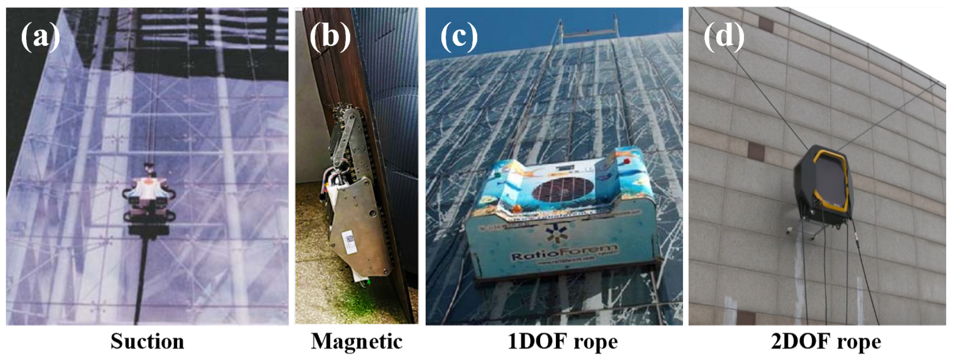
1. Introduction
2. Rope-on-Rope (ROR) System Modeling
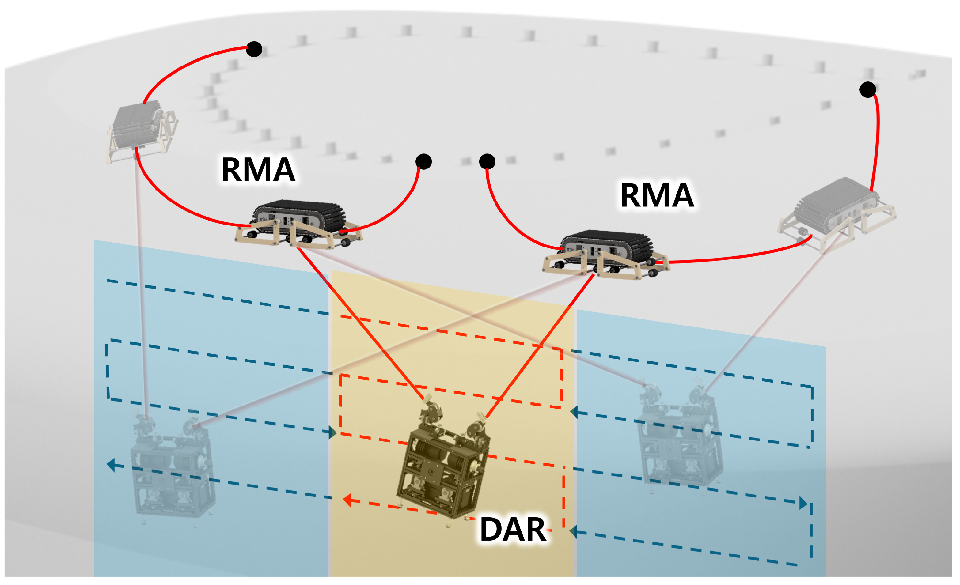
2.1. System Configuration
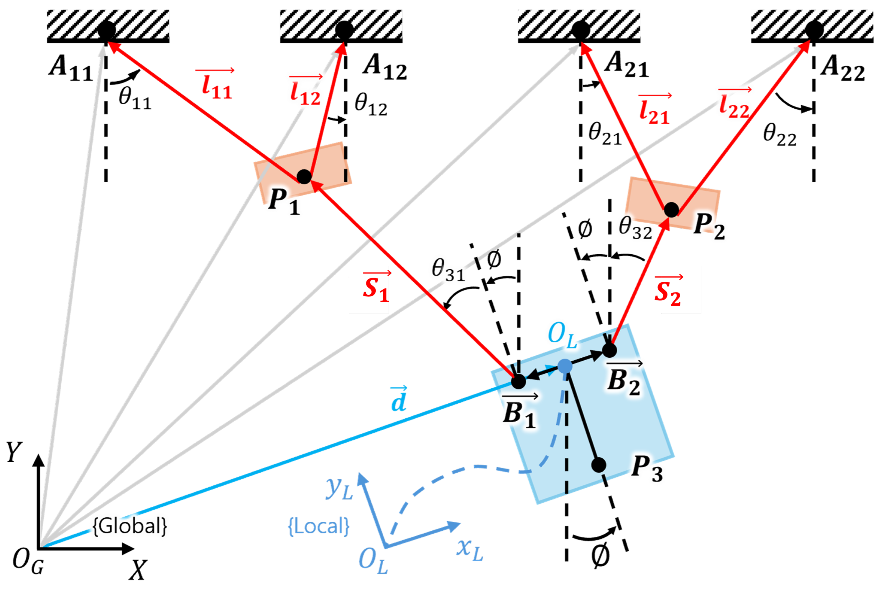
2.2. Kinematic Analysis
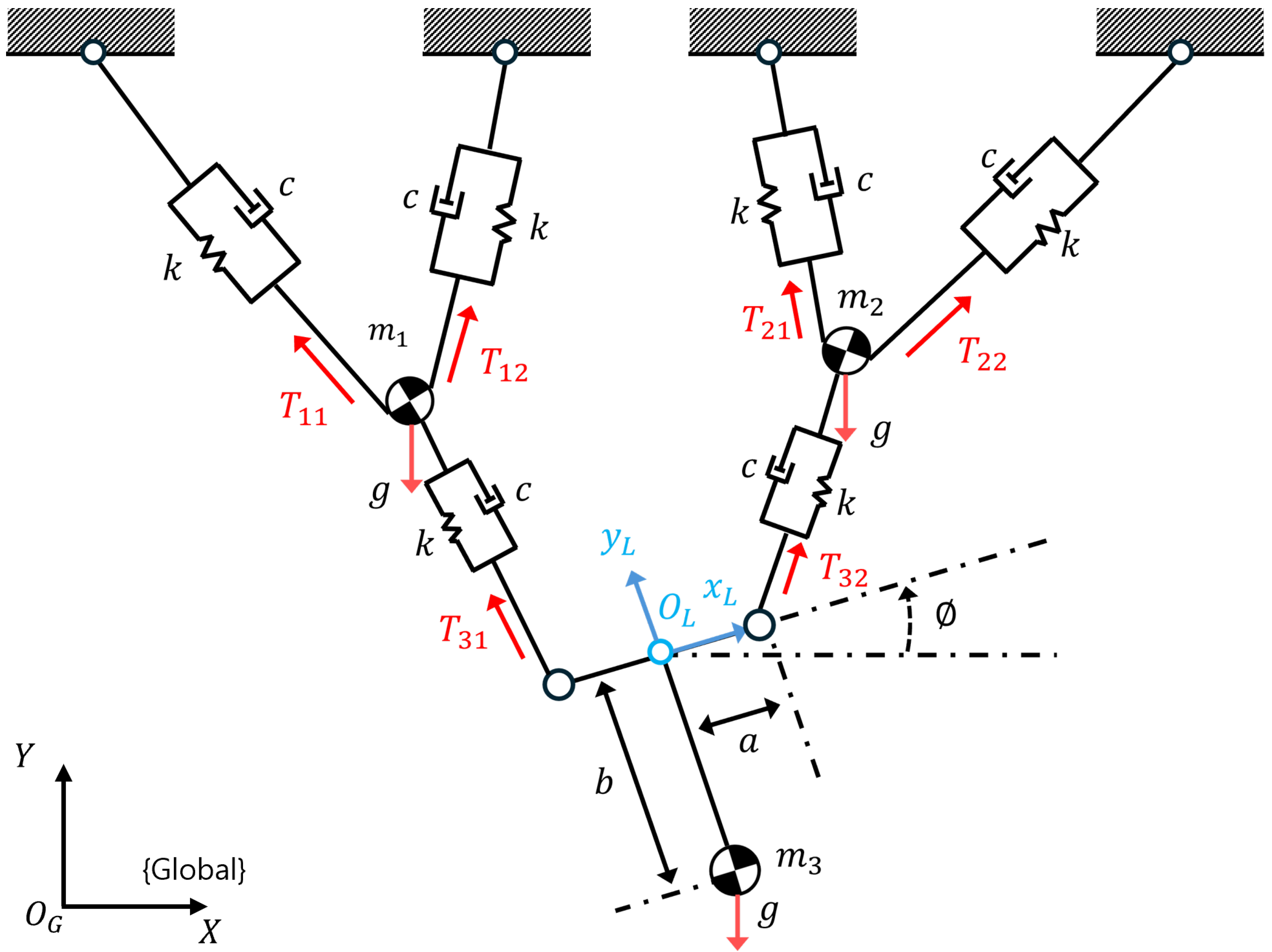
2.3. Dynamic Analysis
3. Residual Vibration Control
3.1. System Analysis
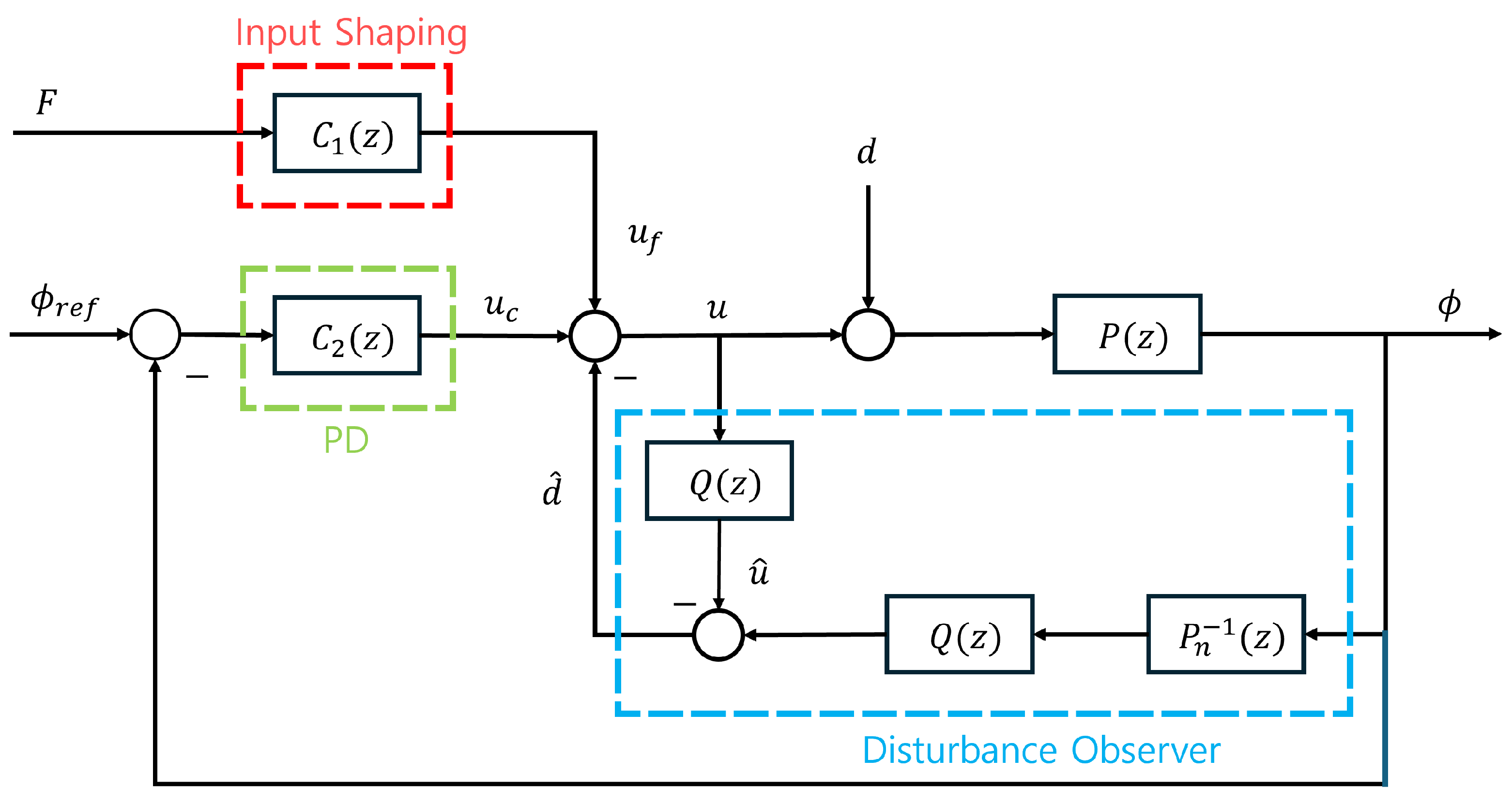
3.2. Disturbance Observer
3.3. Input Shaping
3.4. Control Algorithm
4. Verification Experiment (See Supplementary Materials)
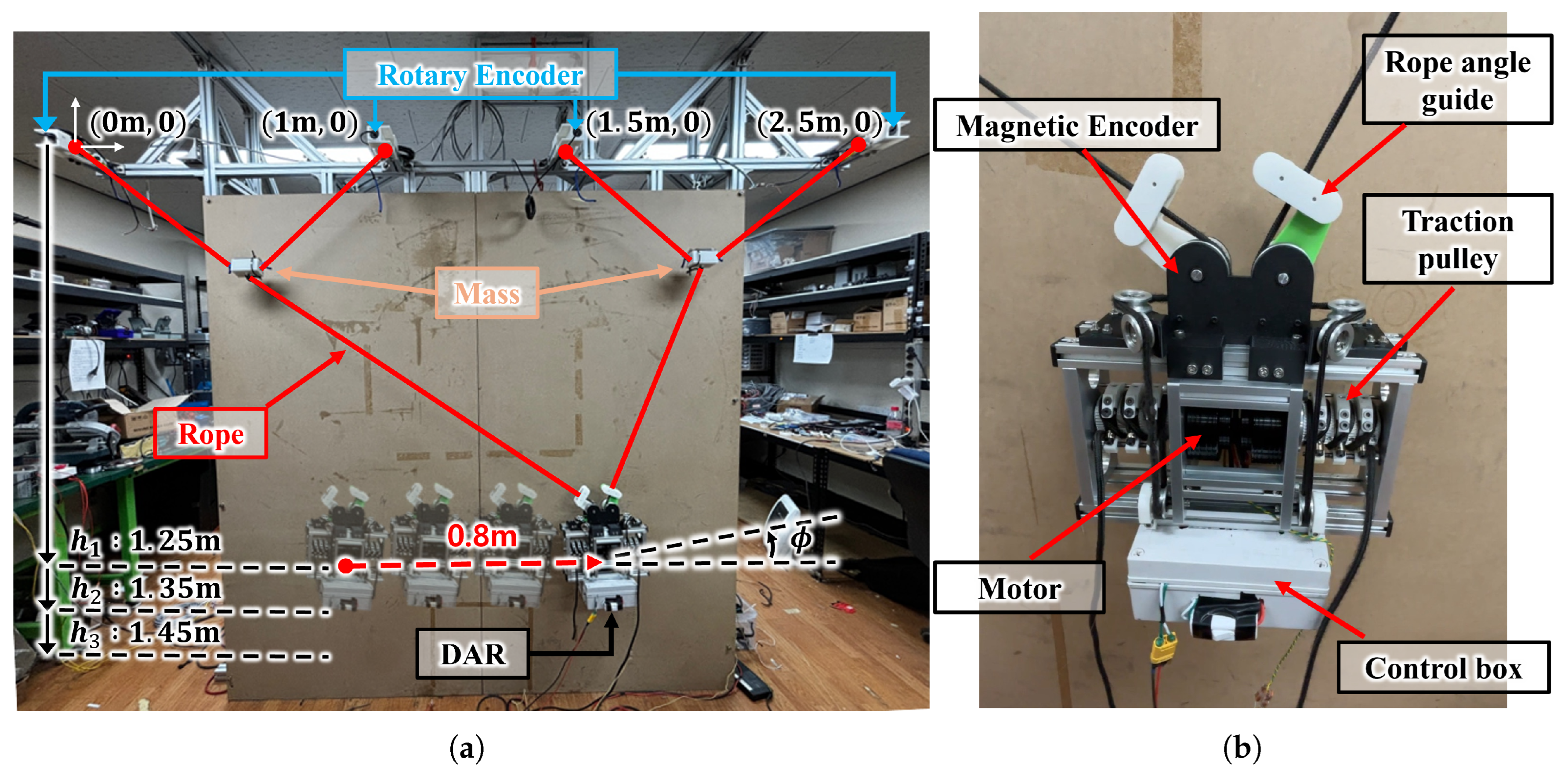
4.1. Experiment Settings
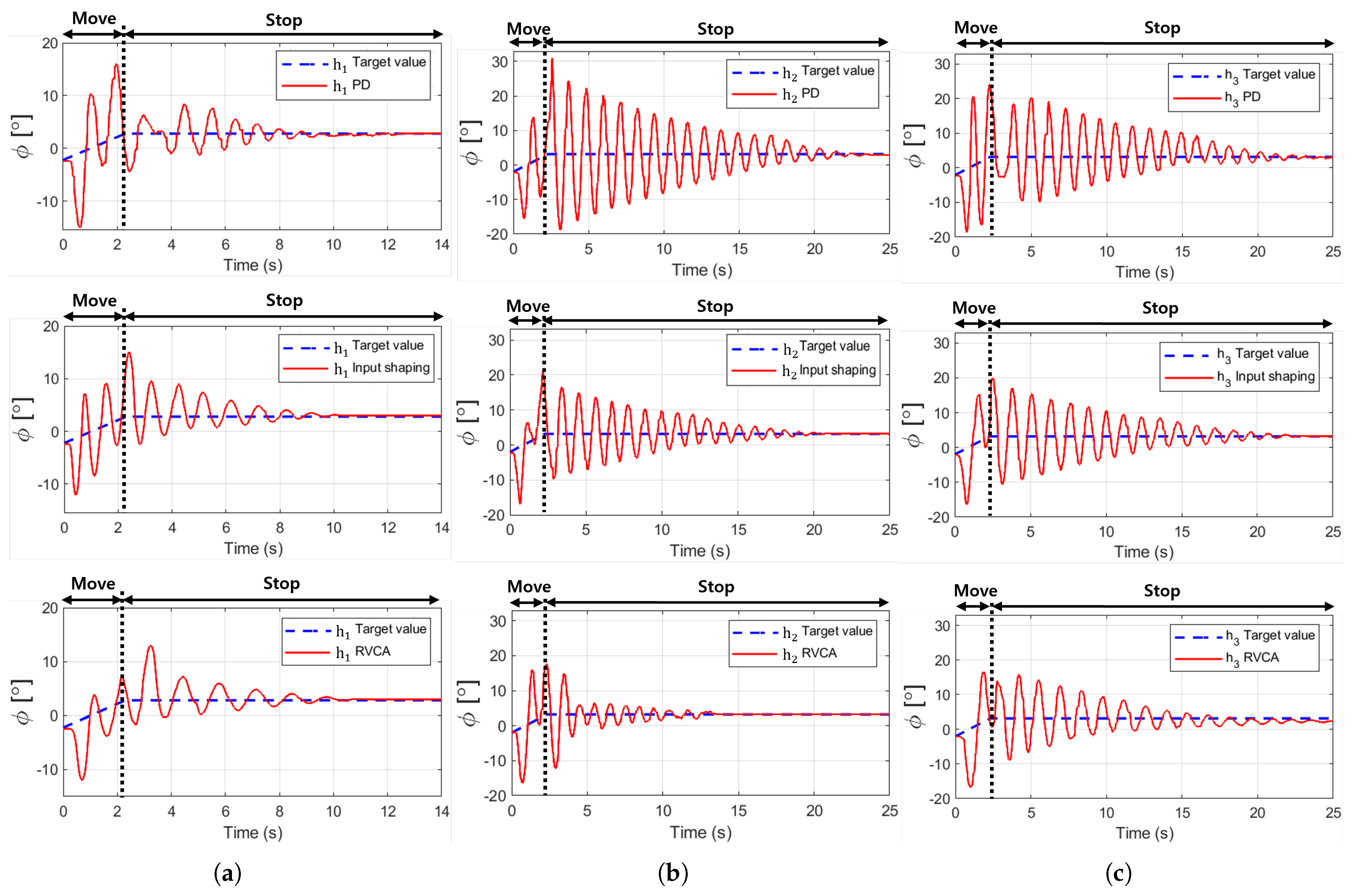
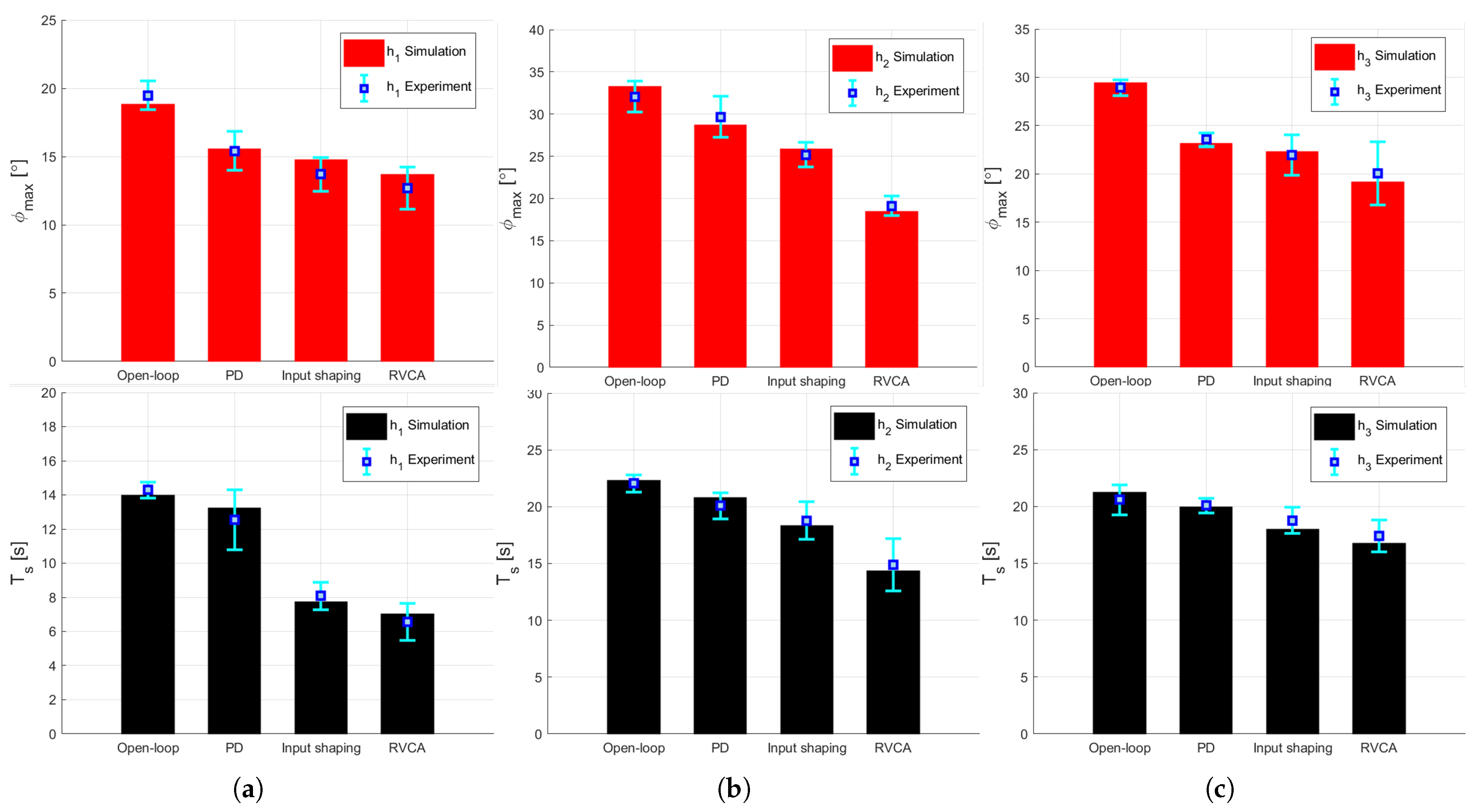
4.2. Experiment Results and Discussion
5. Conclusions
Supplementary Materials
Author Contributions
Funding
Institutional Review Board Statement
Informed Consent Statement
Data Availability Statement
Conflicts of Interest
References
- Zhang, H.; Zhang, J.; Wang, W.; Liu, R.; Zong, G. A series of pneumatic glass-wall cleaning robots for high-rise buildings. Ind. Robot. Int. J. 2007, 34, 150–160. [Google Scholar] [CrossRef]
- Zhang, H.; Zhang, J.; Zong, G.; Wang, W.; Liu, R. Sky cleaner 3: A real pneumatic climbing robot for glass-wall cleaning. IEEE Robot. Autom. Mag. 2006, 13, 32–41. [Google Scholar] [CrossRef]
- Imaoka, N.; Roh, S.g.; Yusuke, N.; Hirose, S. SkyScraper-I: Tethered whole windows cleaning robot. In Proceedings of the 2010 IEEE/RSJ International Conference on Intelligent Robots and Systems, Taipei, Taiwan, 18–22 October 2010; pp. 5460–5465. [Google Scholar]
- Han, S.C.; Kim, J.; Yi, H.C. A novel design of permanent magnet wheel with induction pin for mobile robot. Int. J. Precis. Eng. Manuf. 2009, 10, 143–146. [Google Scholar] [CrossRef]
- Shang, J.; Bridge, B.; Sattar, T.; Mondal, S.; Brenner, A. Development of a climbing robot for inspection of long weld lines. Ind. Robot. Int. J. 2008, 35, 217–223. [Google Scholar] [CrossRef]
- Gao, F.; Fan, J.; Zhang, L.; Jiang, J.; He, S. Magnetic crawler climbing detection robot basing on metal magnetic memory testing technology. Robot. Auton. Syst. 2020, 125, 103439. [Google Scholar] [CrossRef]
- Shen, W.; Gu, J.; Shen, Y. Proposed wall climbing robot with permanent magnetic tracks for inspecting oil tanks. In Proceedings of the IEEE International Conference Mechatronics and Automation, Niagara Falls, ON, Canada, 29 July–1 August 2005; 2005; Volume 4, pp. 2072–2077. [Google Scholar]
- Schoeneich, P.; Rochat, F.; Nguyen, O.T.D.; Moser, R.; Mondada, F. TRIPILLAR: A miniature magnetic caterpillar climbing robot with plane transition ability1. Robotica 2011, 29, 1075–1081. [Google Scholar] [CrossRef]
- Ecovacs Robotics. Winbot Window Cleaning Robot. 2018. Available online: https://www.ecovacs.com/us/campaign/ces-robot-window-cleaner-winbot (accessed on 28 April 2018).
- Akinfiev, T.; Armada, M.; Nabulsi, S. Climbing cleaning robot for vertical surfaces. Ind. Robot. Int. J. 2009, 36, 352–357. [Google Scholar] [CrossRef]
- Chae, H.; Moon, Y.; Lee, K.; Park, S.; Kim, H.S.; Seo, T. A tethered façade cleaning robot based on a dual rope windlass climbing mechanism: Design and experiments. IEEE/ASME Trans. Mechatron. 2022, 27, 1982–1989. [Google Scholar] [CrossRef]
- Rajesh, S.; Janarthanan, P.; Raj, G.; Jaichandran, A. Design and optimization of high rise building cleaner. Int. J. Appl. Eng. Res. 2018, 13, 6881–6885. [Google Scholar]
- Murray, R.M.; Li, Z.; Sastry, S.S. A Mathematical Introduction to Robotic Manipulation; CRC Press: Boca Raton, FL, USA, 2017. [Google Scholar]
- An, H.; Yuan, H.; Tang, K.; Xu, W.; Wang, X. A novel cable-driven parallel robot with movable anchor points capable for obstacle environments. IEEE/ASME Trans. Mechatron. 2022, 27, 5472–5483. [Google Scholar] [CrossRef]
- Umakarthikeyan, S.; R, B.N. Modelling and Simulation of Quadrotor-based Cable-Driven Parallel Manipulator. In Proceedings of the 2022 6th International Conference on Electronics, Communication and Aerospace Technology, Coimbatore, India, 1–3 December 2022; pp. 151–157. [Google Scholar]
- Jamshidifar, H.; Khajepour, A. Static workspace optimization of aerial cable towed robots with land-fixed winches. IEEE Trans. Robot. 2020, 36, 1603–1610. [Google Scholar] [CrossRef]
- Kim, C.; Lee, K.; Yang, J.; Seo, T. Rope-riding mobile anchor for robots operating on convex facade. Robot. Auton. Syst. 2024; submitted. [Google Scholar]
- Leech, C. The Modelling and Analysis of the Mechanics of Ropes; Springer: Berlin/Heidelberg, Germany, 2014. [Google Scholar]
- Cuvillon, L.; Perozo, M.A.; Yiğit, A.; Durand, S.; Gangloff, J. Offset-free nonlinear model predictive control for improving dynamics of cable-driven parallel robots with on-board thrusters. Mech. Mach. Theory 2023, 180, 105141. [Google Scholar] [CrossRef]
- Wang, R. Prototype Design and Time-Optimal Control of a Lower-Mobility Cable-Driven Parallel Robot. Ph.D. Thesis, Hong Kong Polytechnic University, Hong Kong, China, 2023. [Google Scholar]
- Yoo, S.; Kim, T.; Seo, M.; Oh, J.; Kim, H.S.; Seo, T. Position-tracking control of dual-rope winch robot with rope slip compensation. IEEE/ASME Trans. Mechatron. 2021, 26, 1754–1762. [Google Scholar] [CrossRef]
- Choi, M.; Ahn, S.; Kim, H.S.; Seo, T. Modeling and control of TRDMR on a facade with thruster-driven adhesion. Mechatronics 2023, 94, 103038. [Google Scholar] [CrossRef]
- Weber, X.; Cuvillon, L.; Gangloff, J. Active vibration canceling of a cable-driven parallel robot using reaction wheels. In Proceedings of the 2014 IEEE/RSJ International Conference on Intelligent Robots and Systems, Chicago, IL, USA, 14–18 September 2014; pp. 1724–1729. [Google Scholar]
- Allgower, F.; Findeisen, R.; Nagy, Z.K. Nonlinear model predictive control: From theory to application. J.-Chin. Inst. Chem. Eng. 2004, 35, 299–316. [Google Scholar]
- Zhao, H.; Guo, Y.; Li, X.; Liu, Y.; Jin, J. Hierarchical control framework for path planning of mobile robots in dynamic environments through global guidance and reinforcement learning. IEEE Internet Things J. 2024, 12, 309–333. [Google Scholar] [CrossRef]
- Chai, R.; Niu, H.; Carrasco, J.; Arvin, F.; Yin, H.; Lennox, B. Design and experimental validation of deep reinforcement learning-based fast trajectory planning and control for mobile robot in unknown environment. IEEE Trans. Neural Netw. Learn. Syst. 2022, 35, 5778–5792. [Google Scholar] [CrossRef]
- Zhao, H.; Guo, Y.; Liu, Y.; Jin, J. Multirobot unknown environment exploration and obstacle avoidance based on a Voronoi diagram and reinforcement learning. Expert Syst. Appl. 2025, 264, 125900. [Google Scholar] [CrossRef]
- Tho, H.D.; Terashima, K.; Miyoshi, T. Vibration Control of an Overhead Crane with Hoisting Motion using Input Shaping Technique. In Proceedings of the 2022 American Control Conference (ACC), Atlanta, GA, USA, 8–10 June 2022; pp. 1910–1914. [Google Scholar] [CrossRef]
- Tho, H.D.; Terashima, K.; Miyoshi, T. Input Shaping Control of an Overhead Crane with Time-varying Cable Length using a Generalized Input Shaper. In Proceedings of the 2023 American Control Conference (ACC), San Diego, CA, USA, 31 May–2 June 2023; pp. 667–672. [Google Scholar] [CrossRef]
- Seo, M.; Yoo, S.; Choi, M.; Oh, J.; Kim, H.S.; Seo, T. Vibration reduction of flexible rope-driven mobile robot for safe facade operation. IEEE/ASME Trans. Mechatron. 2021, 26, 1812–1819. [Google Scholar] [CrossRef]
- Chen, W.H.; Yang, J.; Guo, L.; Li, S. Disturbance-observer-based control and related methods—An overview. IEEE Trans. Ind. Electron. 2015, 63, 1083–1095. [Google Scholar] [CrossRef]
- Singer, N.C.; Seering, W.P. Preshaping command inputs to reduce system vibration. J. Dyn. Syst. Meas. Control 1990, 112, 76–82. [Google Scholar] [CrossRef]


| Symbol | Description |
|---|---|
| Vector of fixed anchor points | |
| Vector of magnetic encoders | |
| RMA’s vector of rope | |
| DAR’s vector of rope | |
| Angle between the rope and the vertical reference line | |
| Angle representing the magnitude of residual vibration | |
| x position of robots | |
| y position of robots | |
| k | Spring coefficient of rope |
| c | Damping coefficient of rope |
| g | Gravitational constant |
| Tension of rope | |
| Mass of robot | |
| I | DAR’s moment of inertia |
| Item | Manufacturer | Model |
|---|---|---|
| BLDC Motor | Cubemars | AK60-6 |
| Rotary Encoder | Autonics | E30S |
| Magnetic Encoder | SEINFLEX | D30 |
| IMU | E2BOX | EBIMU-9DOFv5 |
| Experiment Condition | Open Loop | PD | Input Shaping | RVCA | |
|---|---|---|---|---|---|
| 19.48 | 15.42 (▾20.84%) | 13.69 (▾29.72%) | 12.67 (▾34.9%) | ||
| Max. amplitude() [°] | 32.04 | 29.67 (▾7.40%) | 25.19 (▾21.38%) | 19.13 (▾40.29%) | |
| 28.92 | 23.56 (▾18.53%) | 21.93 (▾24.17%) | 20.05 (▾30.67%) | ||
| 14.29 | 12.56 (▾12.11%) | 8.09 (▾43.39%) | 6.57 (▾54.02%) | ||
| Settling time() [s] | 22.04 | 20.08 (▾8.89%) | 18.78 (▾14.80%) | 14.91 (▾32.35%) | |
| 20.59 | 20.08 (▾2.48%) | 18.78 (▾8.79%) | 17.41 (▾15.44%) | ||
| RMSE() [°] | 6.9183 | 5.1903 | 4.0391 | 3.4135 | |
Disclaimer/Publisher’s Note: The statements, opinions and data contained in all publications are solely those of the individual author(s) and contributor(s) and not of MDPI and/or the editor(s). MDPI and/or the editor(s) disclaim responsibility for any injury to people or property resulting from any ideas, methods, instructions or products referred to in the content. |
© 2025 by the authors. Licensee MDPI, Basel, Switzerland. This article is an open access article distributed under the terms and conditions of the Creative Commons Attribution (CC BY) license (https://creativecommons.org/licenses/by/4.0/).
Share and Cite
Lee, K.; Ahn, S.; Yang, J.; Kim, H.; Seo, T. Rope on Rope: Reducing Residual Vibrations in Rope-Based Anchoring System and Rope-Driven Façade Operation Robot. Sensors 2025, 25, 2463. https://doi.org/10.3390/s25082463
Lee K, Ahn S, Yang J, Kim H, Seo T. Rope on Rope: Reducing Residual Vibrations in Rope-Based Anchoring System and Rope-Driven Façade Operation Robot. Sensors. 2025; 25(8):2463. https://doi.org/10.3390/s25082463
Chicago/Turabian StyleLee, Kangyub, Sahoon Ahn, Jeongmo Yang, Hwasoo Kim, and Taewon Seo. 2025. "Rope on Rope: Reducing Residual Vibrations in Rope-Based Anchoring System and Rope-Driven Façade Operation Robot" Sensors 25, no. 8: 2463. https://doi.org/10.3390/s25082463
APA StyleLee, K., Ahn, S., Yang, J., Kim, H., & Seo, T. (2025). Rope on Rope: Reducing Residual Vibrations in Rope-Based Anchoring System and Rope-Driven Façade Operation Robot. Sensors, 25(8), 2463. https://doi.org/10.3390/s25082463