
High-Precision 2D-DOA Estimation Method for Millimeter-Wave Radar Based on Double-Parallel Linear Array and Joint IAA-RIT


Abstract
1. Introduction
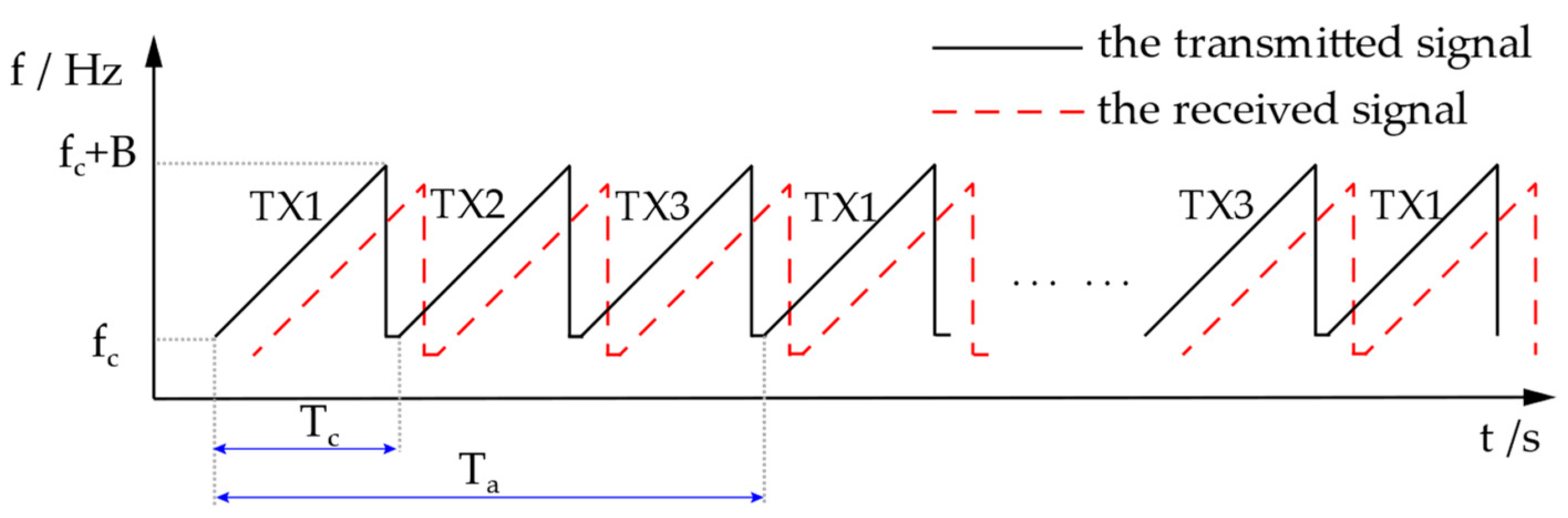
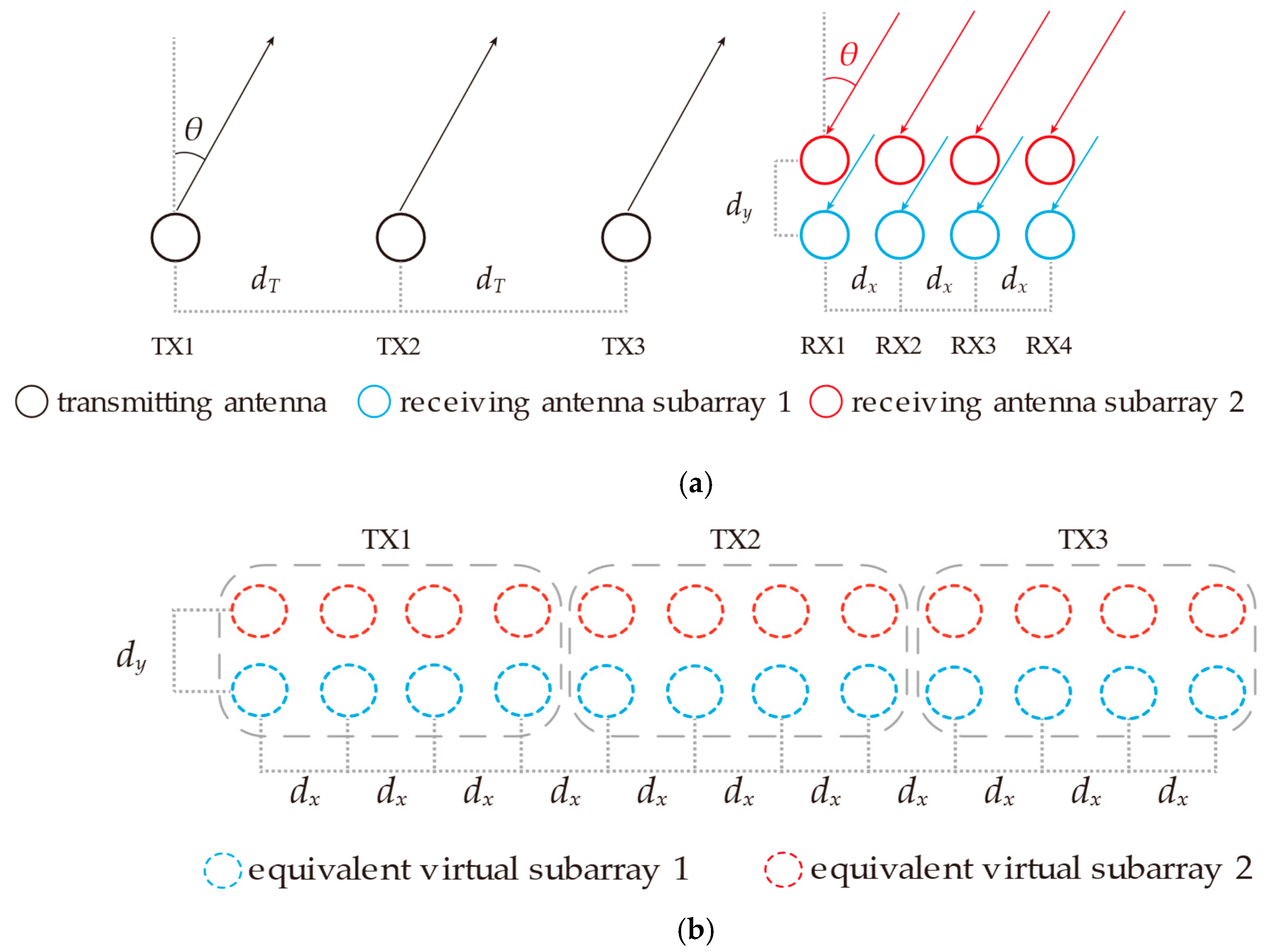
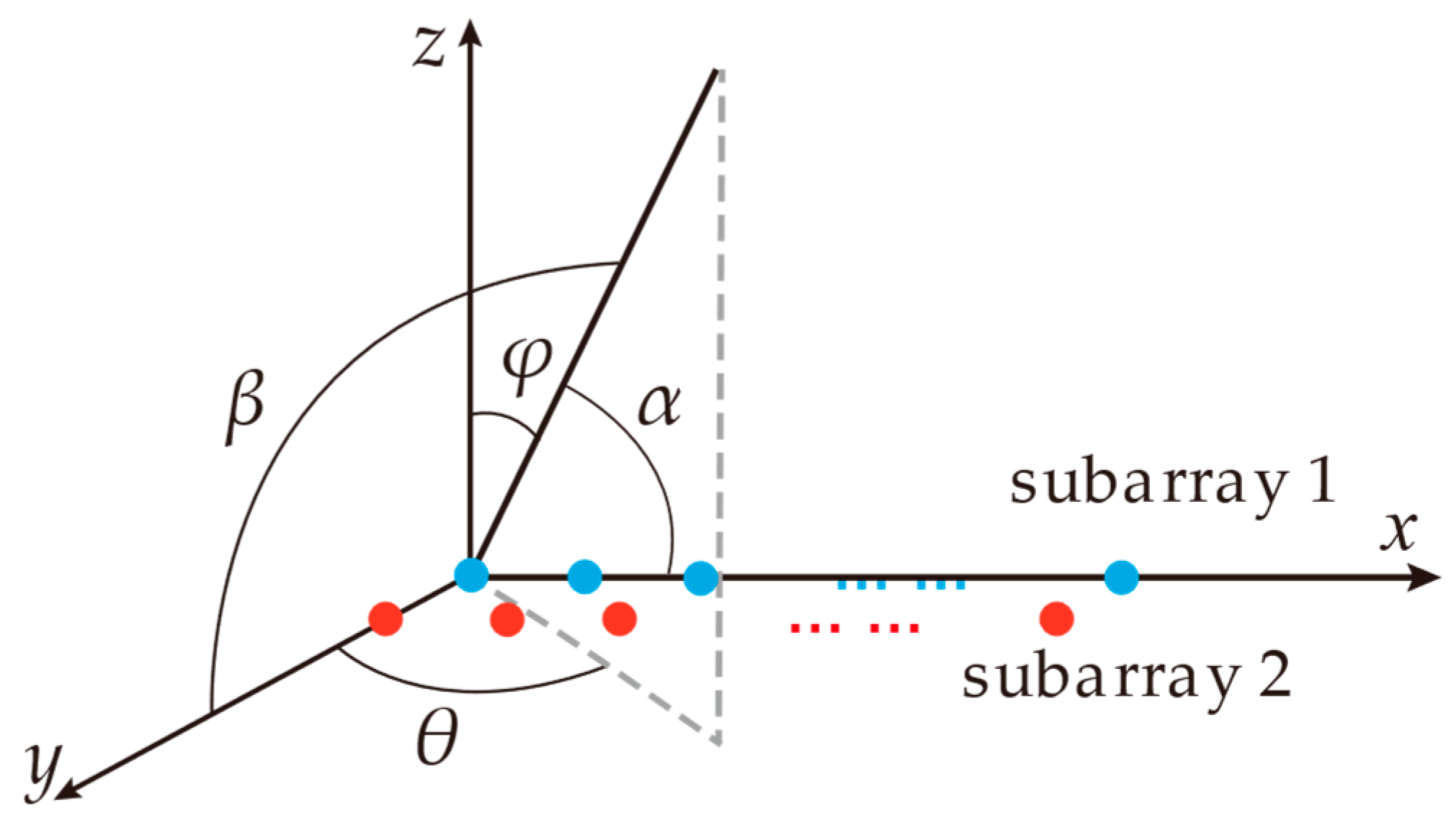
2. Signal Model
3. High-Precision 2D-DOA Estimation Method
3.1. Generation of the Range-Doppler Spectrum
3.2. Doppler Phase Compensation Technique
3.3. High-Precision 2D-DOA Estimation Method Combining IAA and RIT
4. Simulation Experiment
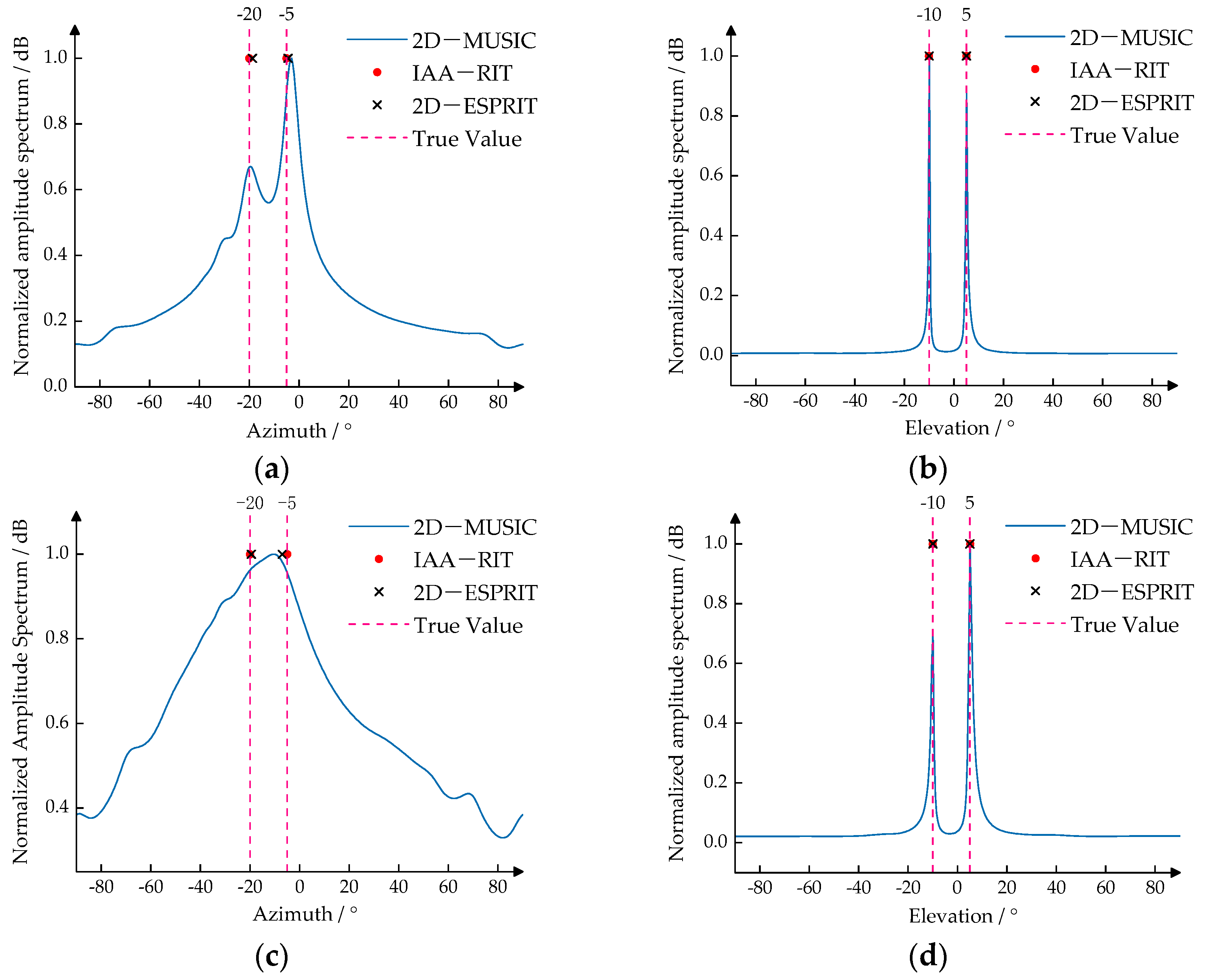
4.1. Verification Experiment on the Angular Resolution Performance of IAA-RIT
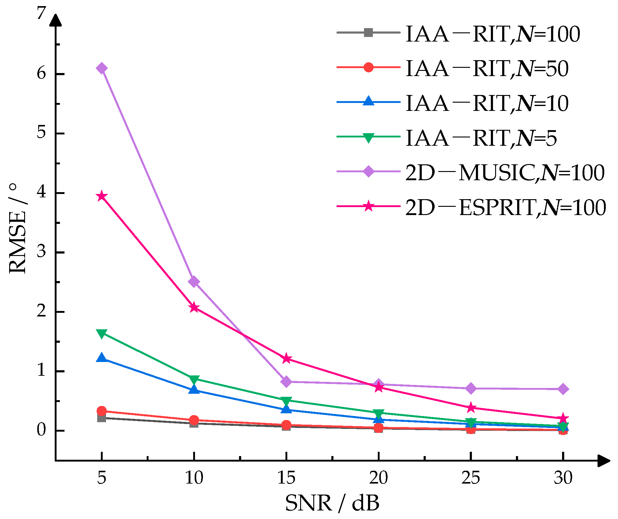
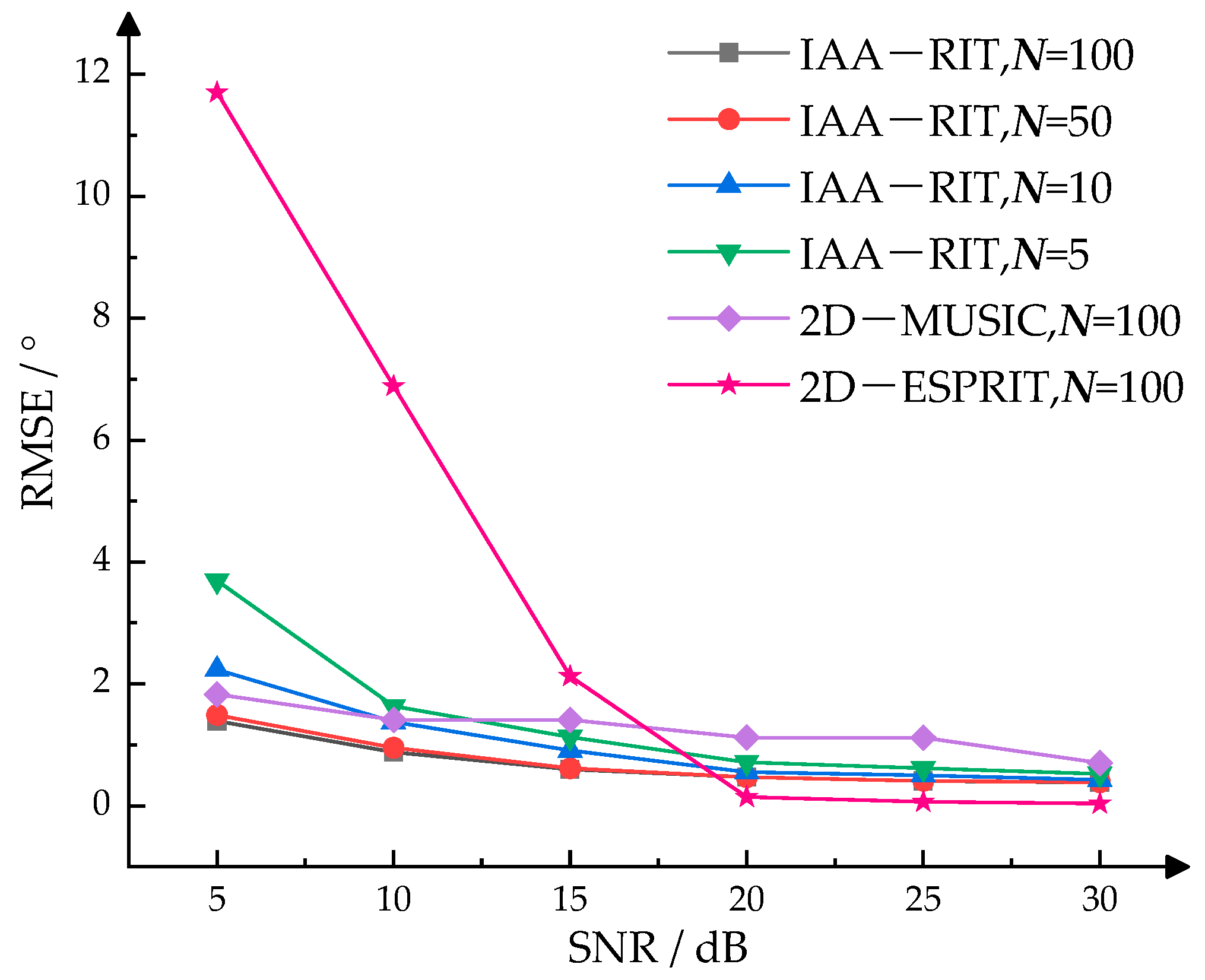
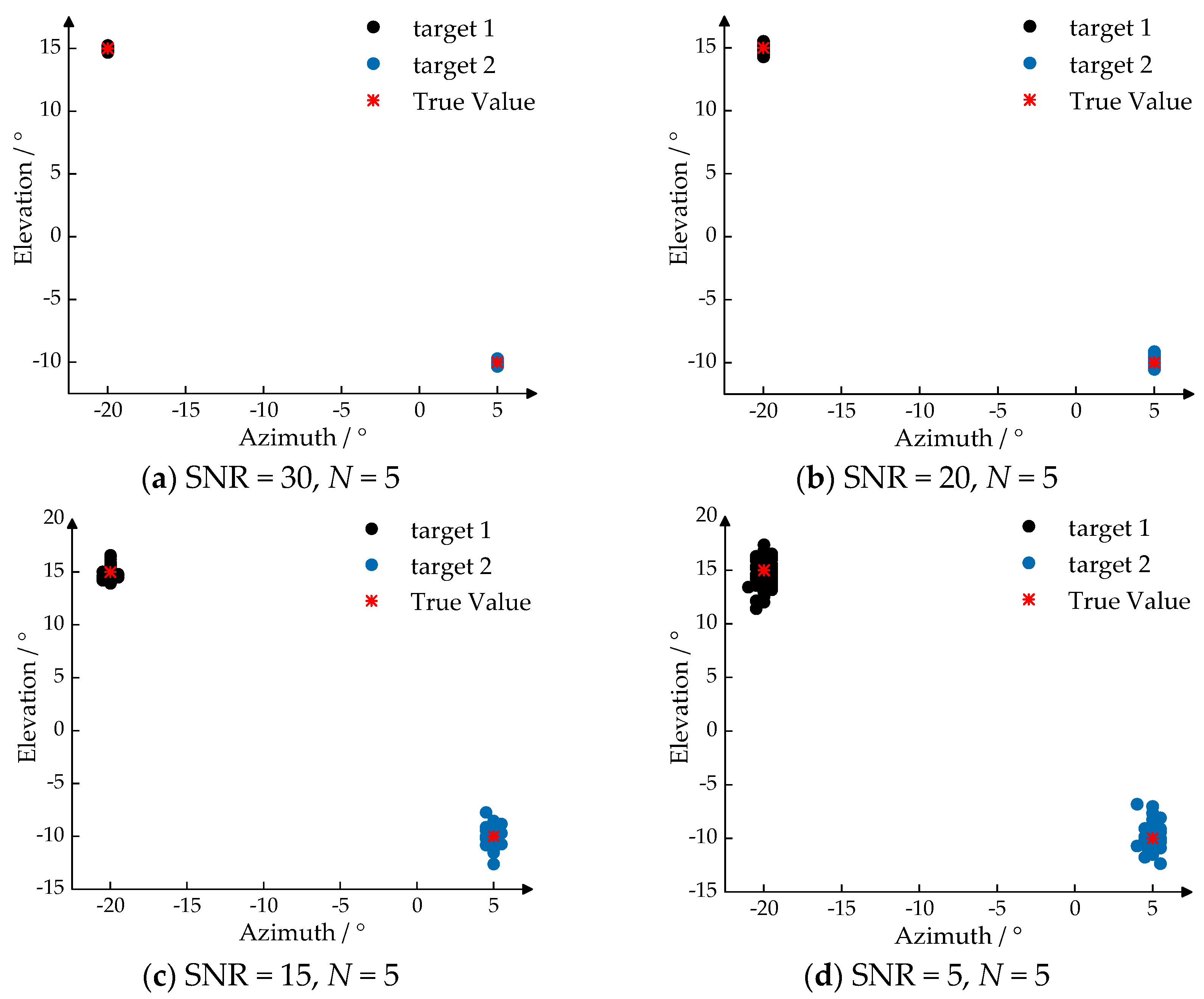
4.2. Verification of High-Precision Estimation Performance for the IAA-RIT
4.3. Verification Experiment on the Angle Resolution Performance and Estimation Accuracy of Coherent Source
5. Conclusions
Author Contributions
Funding
Institutional Review Board Statement
Informed Consent Statement
Data Availability Statement
Conflicts of Interest
References
- Jiang, M.J.; Xu, G.; Pei, H.; Feng, Z.Y.; Ma, S.A.; Zhang, H. 4D High-Resolution Imagery of Point Clouds for Automotive mmWave Radar. IEEE Trans. Intell. Transp. Syst. 2024, 25, 998–1012. [Google Scholar] [CrossRef]
- Cai, X.Z.; Giallorenzo, M.; Sarabandi, K. Machine Learning-Based Target Classification for MMW Radar in Autonomous Driving. IEEE Trans. Intell. Vehicles 2021, 6, 678–689. [Google Scholar] [CrossRef]
- Wang, T.; Wu, S.; Cao, L.; Du, K.; Zhao, Z.; He, Z. A Novel Possibilistic Clustering Algorithm for Measurement Data of Vehicle MMW Radar. IEEE Sens. J. 2023, 23, 17103–17116. [Google Scholar] [CrossRef]
- Liu, Y.Q.; Tao, M.Y.; Shi, T.Y.; Wang, J.P.; Wang, J.H.; Mao, X.H. Sub-Aperture Polar Format Algorithm for Curved Trajectory Millimeter-wave Radar Imaging. IEEE Trans. Radar Syst. 2024, 2, 67–83. [Google Scholar] [CrossRef]
- LI, X.R.; Wang, X.D.; Yang, Q.; Fu, S. Signal Processing for TDM MIMO FMCW Millimeter-Wave Radar Sensors. IEEE Access 2021, 9, 167959–167971. [Google Scholar] [CrossRef]
- Engels, F.; Heidenreich, P.; Wintermantel, M.; Stäcker, L.; Kadi, M.A.; Zoubir, A.M. Automotive Radar Signal Processing: Research Directions and Practical Challenges. IEEE J. Sel. Top. Signal Process. 2021, 15, 865–878. [Google Scholar] [CrossRef]
- Patole, S.M.; Torlak, M.; Wang, D.; Ali, M. Automotive radars: A review of signal processing techniques. IEEE Signal Proc. Mag. 2017, 34, 22–35. [Google Scholar] [CrossRef]
- Sun, S.; Petropulu, A.P.; Poor, H.V. MIMO Radar for Advanced Driver-Assistance Systems and Autonomous Driving: Advantages and Challenges. IEEE Signal Proc. Mag. 2020, 37, 98–117. [Google Scholar] [CrossRef]
- Rambach, K.; Yang, B. MIMO Radar: Time Division Multiplexing vs. Code Division Multiplexing. In Proceedings of the International Conference on Radar Systems, Belfast, UK, 23–26 October 2017. [Google Scholar]
- Duly, A.J.; Love, D.J.; Krogmeier, J.V. Time-Division Beamforming for MIMO Radar Waveform Design. IEEE Trans. Aerosp. Electron. Syst. 2013, 49, 1210–1223. [Google Scholar] [CrossRef]
- Zhang, Z.Y. Research on Optimization Design and DOA Estimation Method of Millimeter-Wave MIMO Radar Array. Master’s Thesis, University of Electronic Science and Technology, Chengdu, China, 2023. [Google Scholar]
- Liu, X.J. Research on DOA Estimation Technology of Vehicle Mounted Millimeter-Wave Radar Based on MIMO Array. Master’s Thesis, University of Electronic Science and Technology, Chengdu, China, 2023. [Google Scholar]
- Liu, Z.; Wu, J.Y.; Yang, S.Y.; Lu, W. DOA Estimation Method Based on EMD and MUSIC for Mutual Interference in FMCW Automotive Radars. IEEE Geosci. Remote Sens. Lett. 2022, 19, 1–5. [Google Scholar] [CrossRef]
- Karmous, N.; Hassan, M.O.E.; Choubeni, F. An Improved Esprit Algorithm for DOA Estimation of Coherent Signals. In Proceedings of the International Conference on Smart Communications and Networking (SmartNets), Yasmine Hammamet, Tunisia, 16–17 November 2018. [Google Scholar]
- Malioutov, D.; Cetin, M.; Willsky, A.S. A sparse signal reconstruction perspective for source localization with sensor arrays. IEEE Trans. Signal Process. 2005, 53, 3010–3022. [Google Scholar] [CrossRef]
- Wei, S.J.; Zhou, Z.C.; Wang, M.; Zhang, H.; Shi, J.; Zhang, X.L. Learning-Based Split Unfolding Framework for 3-D mmW Radar Sparse Imaging. IEEE Trans. Geosci. Remote Sens. 2022, 60, 1–17. [Google Scholar] [CrossRef]
- Li, Z.G.; Li, S.Q.; Wen, S.L. An Improved DOA Estimation Method Based on Orthogonal Matching Pursuit. Meas. Control Technol. 2017, 36, 27–31+36. [Google Scholar]
- Zhang, Y.; Jing, X.L.; Jiang, Z.J. An Off-Grid DOA Estimation Algorithm Based on Sparse Bayesian Learning. Radar Sci. Technol. 2024, 22, 35–42. [Google Scholar]
- Yardibi, T.; Li, J.; Stoica, P.; Xue, M.; Baggeroer, A.B. Source Localization and Sensing: A Nonparametric Iterative Adaptive Approach Based on Weighted Least Squares. IEEE Trans. Aerosp. Electron. Syst. 2010, 46, 425–443. [Google Scholar] [CrossRef]
- Xue, M.; Xu, L.Z.; Li, J. IAA Spectral Estimation: Fast Implementation Using the Gohberg–Semencul Factorization. IEEE Trans. Signal Process. 2011, 59, 3251–3261. [Google Scholar]
- Chen, Y.; Huang, L.T.; So, H.C. Selective Range Iterative Adaptive Approach for High-Resolution DOA Estimation. IEEE Access 2019, 7, 15634–15640. [Google Scholar] [CrossRef]
- Jie, Y.K.; Zhang, W.; Li, X.; Ye, X.D.; Wang, H.; Tao, S.F. An Off-Grid Estimation Based on Iterative Adaptive Approach. J. Electron. Inf. Techn. 2023, 45, 3805–3811. [Google Scholar]
- Stoica, P.; Babu, P.; Li, J. SPICE: A Sparse Covariance-Based Estimation Method for Array Processing. IEEE Trans. Signal Process. 2011, 59, 629–638. [Google Scholar] [CrossRef]
- Yin, Q.Y.; Zou, L.H.; Newcomb, R.W. A high resolution approach to 2D signal parameter estimation DOA matrix method. J. China Inst. Commun. 1991, 4, 1–7+44. [Google Scholar]
- Zheng, C.; Yang, Z.Q. DOA Estimation of Coherent Signal Sources using Spatial Smoothing Music Algorithms. Fire Control Radar Technol. 2021, 50, 21–24. [Google Scholar]
- Du, L.; Sun, Q.; Bai, J.; Wang, J. A Verification Method for Traffic Radar-Based Speed Meter with Target Position Determination in Road Vehicle Speeding Enforcement. IEEE Trans. Veh. Technol. 2021, 12, 12374–12388. [Google Scholar] [CrossRef]
Disclaimer/Publisher’s Note: The statements, opinions and data contained in all publications are solely those of the individual author(s) and contributor(s) and not of MDPI and/or the editor(s). MDPI and/or the editor(s) disclaim responsibility for any injury to people or property resulting from any ideas, methods, instructions or products referred to in the content. |
© 2025 by the authors. Licensee MDPI, Basel, Switzerland. This article is an open access article distributed under the terms and conditions of the Creative Commons Attribution (CC BY) license (https://creativecommons.org/licenses/by/4.0/).
Share and Cite
Yu, D.; Du, L.; Bai, J.; Chen, Y. High-Precision 2D-DOA Estimation Method for Millimeter-Wave Radar Based on Double-Parallel Linear Array and Joint IAA-RIT. Sensors 2025, 25, 2609. https://doi.org/10.3390/s25082609
Yu D, Du L, Bai J, Chen Y. High-Precision 2D-DOA Estimation Method for Millimeter-Wave Radar Based on Double-Parallel Linear Array and Joint IAA-RIT. Sensors. 2025; 25(8):2609. https://doi.org/10.3390/s25082609
Chicago/Turabian StyleYu, Danyang, Lei Du, Jie Bai, and Yulin Chen. 2025. "High-Precision 2D-DOA Estimation Method for Millimeter-Wave Radar Based on Double-Parallel Linear Array and Joint IAA-RIT" Sensors 25, no. 8: 2609. https://doi.org/10.3390/s25082609
APA StyleYu, D., Du, L., Bai, J., & Chen, Y. (2025). High-Precision 2D-DOA Estimation Method for Millimeter-Wave Radar Based on Double-Parallel Linear Array and Joint IAA-RIT. Sensors, 25(8), 2609. https://doi.org/10.3390/s25082609