Article

Accuracy of Computer-Assisted Dynamic Navigation as a Function of Different Intraoral Reference Systems: An In Vitro Study

1
Centre for Dentistry, Dr Schnutenhaus Community Health Centre (CHC) GmbH, 78247 Hilzingen, Germany
2
Department for Dentistry, Clinic for Prosthodontics, Ulm University, 89081 Ulm, Germany
*
Author to whom correspondence should be addressed.
Int. J. Environ. Res. Public Health 2021, 18(6), 3244; https://doi.org/10.3390/ijerph18063244
Submission received: 6 February 2021 / Revised: 12 March 2021 / Accepted: 18 March 2021 / Published: 21 March 2021
(This article belongs to the Section Oral Health)

Abstract

:
The aim of this in vitro study was to determine whether the process chain influences the accuracy of a computer-assisted dynamic navigation procedure. Four different data integration workflows using cone-beam computed tomography (CBCT), conventional impressions, and intraoral digitization with and without reference markers were analyzed. Digital implant planning was conducted using data from the CBCT scans and 3D data of the oral models. The restoration of the free end of the lower jaw was simulated. Fifteen models were each implanted with two new teeth for each process chain. The models were then scanned with scan bodies screwed onto the implants. The deviations between the planned and achieved implant positions were determined. The evaluation of all 120 implants resulted in a mean angular deviation of 2.88 ± 2.03°. The mean 3D deviation at the implant shoulder was 1.53 ± 0.70 mm. No significant differences were found between the implant regions. In contrast, the workflow showed significant differences in various parameters. The position of the reference marker affected the accuracy of the implant position. The in vitro examination showed that precise implantation is possible with the dynamic navigation system used in this study. The results are of the same order of magnitude that can be achieved using static navigation methods. Clinical studies are yet to confirm the results of this study.

1. Introduction

The objective of prosthetic implant restoration is to restore the masticatory organs after tooth loss. Therefore, the functional and esthetic rehabilitation should be as natural as possible [1]. The long-term success of implant restoration is determined by multiple factors [2]. When planning implant positions, various aspects must be considered and assessed equally. For example, the bone condition [3], soft tissue condition [4], distances between the implants and neighboring teeth [5], and position of the cement space [6] must be considered while planning an implant position. Prosthetic-driven planning is shown to be suitable for achieving this goal in an optimal and predictable manner [7]. A previous study reported implants placed using computer-assisted procedures had a similar one-year survival rate as implants placed via a conventional procedure [8]. However, patient pain and discomfort are significantly reduced when a flapless procedure is used [9]
Digital 3D planning has been used to achieve favorable implant positioning. The actual condition of the alveolar bone is recorded using three-dimensional imaging (computed tomography (CT) or cone beam computed tomography (CBCT)), and merged with the target of a digitized prosthetic planning goal [1]. Computer-assisted procedures enable the implementation of digital implant planning [10]. In static navigation, drill templates are used to implement the planning. The use of drill templates for implants has been extensively examined [11]. This procedure has proven to be clinically accurate and achieves predictable results [12,13]. Various studies regarding the accuracy of static navigation have identified influencing factors including intraoral positioning and fixation of templates [14]. The manufacturing process for the drill template can also impact the accuracy of implant placement, as can the materials used [15,16,17]. Several studies have reported the influence of different drill sleeves on accuracy [18,19,20]. However, major inaccuracies in the implementation can often be traced back to application errors, not to the actual process [21].
In addition to static computer-assisted surgical procedures, dynamic procedures are also available [1]. The preparation of the implant bed and implant insertion are achieved by a surgeon who navigates the oral cavity with a three-dimensional representation of the actual implant bed on a screen [22]. The positions of the instruments are recognized in real-time using optical tracking systems with defined reference markers and are displayed on a screen [23]. These procedures have been introduced in various preclinical studies [24,25,26]. The development of computer technology and associated computer-aided methods has increased the use of dynamic navigation in clinical practice in recent years [1]. Due to the open-source systems, any implant systems can be used with dynamic navigation; however, it is not possible to store a static template using these systems [1]. The implantation is conducted with real-time visualization, allowing for intraoperative modifications of the plan [13]. Dynamic navigation can also be used when there is little vertical space, unlike drill templates [27]. However, the complexity of the surgical procedure requires sufficient training, and a learning curve has been reported [28]. The results of a systematic review on the accuracy of dynamic computer-assisted navigation revealed comparable clinical outcomes to those of static navigation. However, there is heterogeneity among individual dynamic navigation systems that must be considered [29]. The development of surgical implant procedures based on virtual and augmented reality technologies has resulted in an increase in the quality of restoration [30].
The aims of this in vitro study were to determine influencing factors on the accuracy of a dynamic navigation procedure and to clarify whether the workflow of implant planning and the implementation of 3D planning affect accuracy. In addition, we examined whether the position of the implant and the resulting relative position of the marker affect the accuracy.

2. Materials and Methods

In this controlled in vitro study, four process chains (Table 1) of data integration for implementing dynamic navigation were examined. In addition, the accuracy of the overall system and variables related to the implant region were analyzed. Fifteen identical models made of hard plastic (mandible B6 Bone Standard, GOS Göttinger OP-Simulationssysteme, Northeim, Germany) were used for each of the four process chains. These models represented a partially edentulous lower jaw with a unilateral free-end in regions 45–48 that required restoration.

2.1. Implantation Planning and Models

Individual planning for the two implants was performed for each model using implant planning software (coDiagnostiX Version 9.11, Dental Wings GmbH, Chemnitz, Germany). The planning data were loaded and digitally assigned to each other.. The planning data differed for each process chain.
An implant in region 45 (bone level tapered, BLT) with a diameter of 3.3 mm and length of 10 mm (Straumann Institut AG, Basel, Switzerland) and an implant in region 47 (BLT) with a diameter of 4.1 mm and length of 10 mm (Straumann Institut AG, Basel, Switzerland) were planned. The implant planning was based on prosthetic principles. The implants were centered on the ridge in a vestibular-lingual alignment. The distance between the two implants was 15 mm in each case. The implants were aligned parallel to one another using the parallelization function of the program. After the planning was completed, the data were transferred to the navigation system. The CBCT, planning, and marker positioning data were converted into a form that the navigation system could read using a function of the coDiagnostiX planning software. All planning steps were performed by an experienced dentist (A.K.).
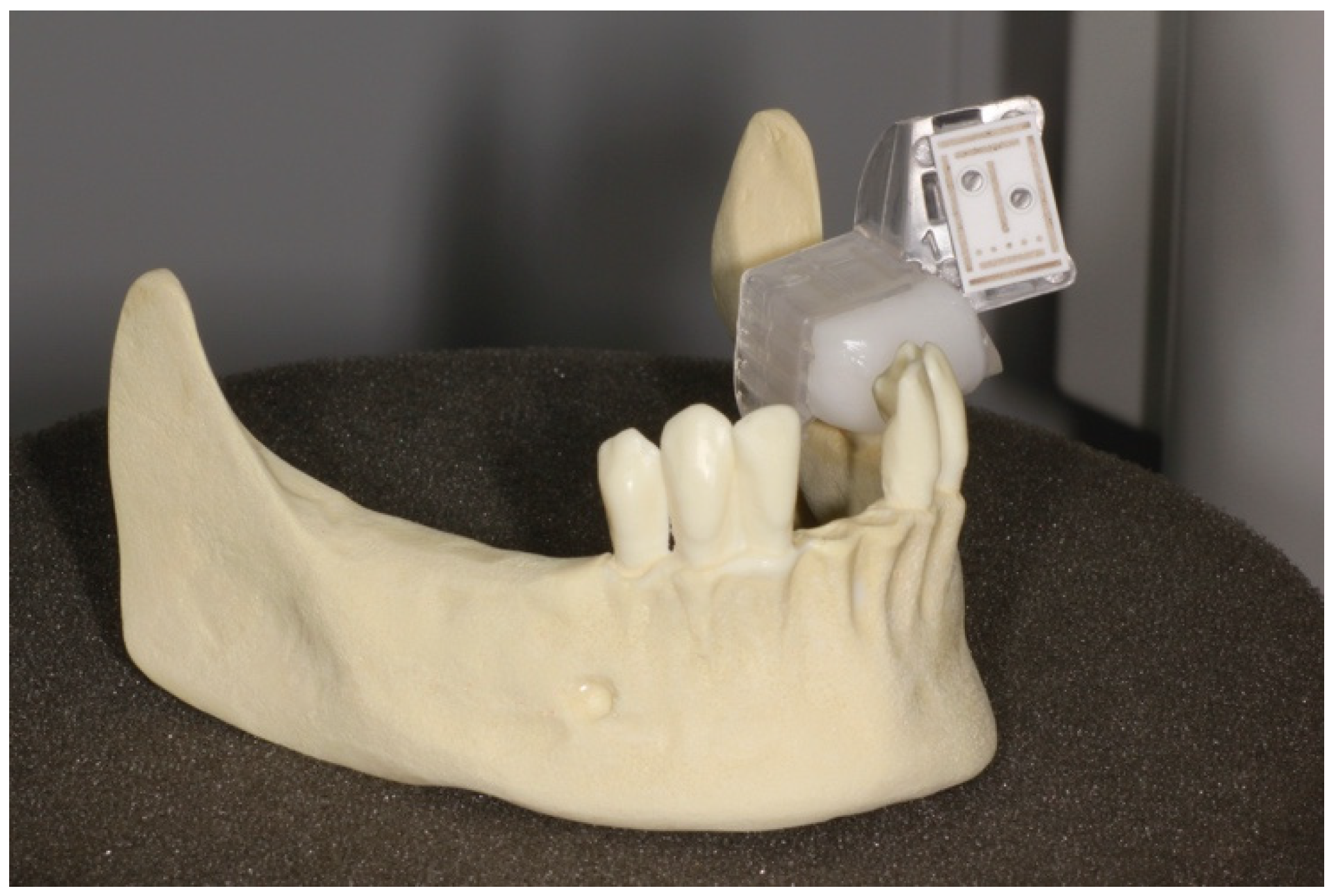
The data were transferred to a DENACAM navigation system (Mininavident AG, Liestal, Switzerland). The DENACAM system works with a camera attached to the surgical handpiece (Figure 1). A marker is placed in the mouth, or in this case, on the model as a reference structure (Figure 2). The system is guided using a 3D display on a screen that is clearly visible to the surgeon. The position, angle, and depth are displayed in real-time.
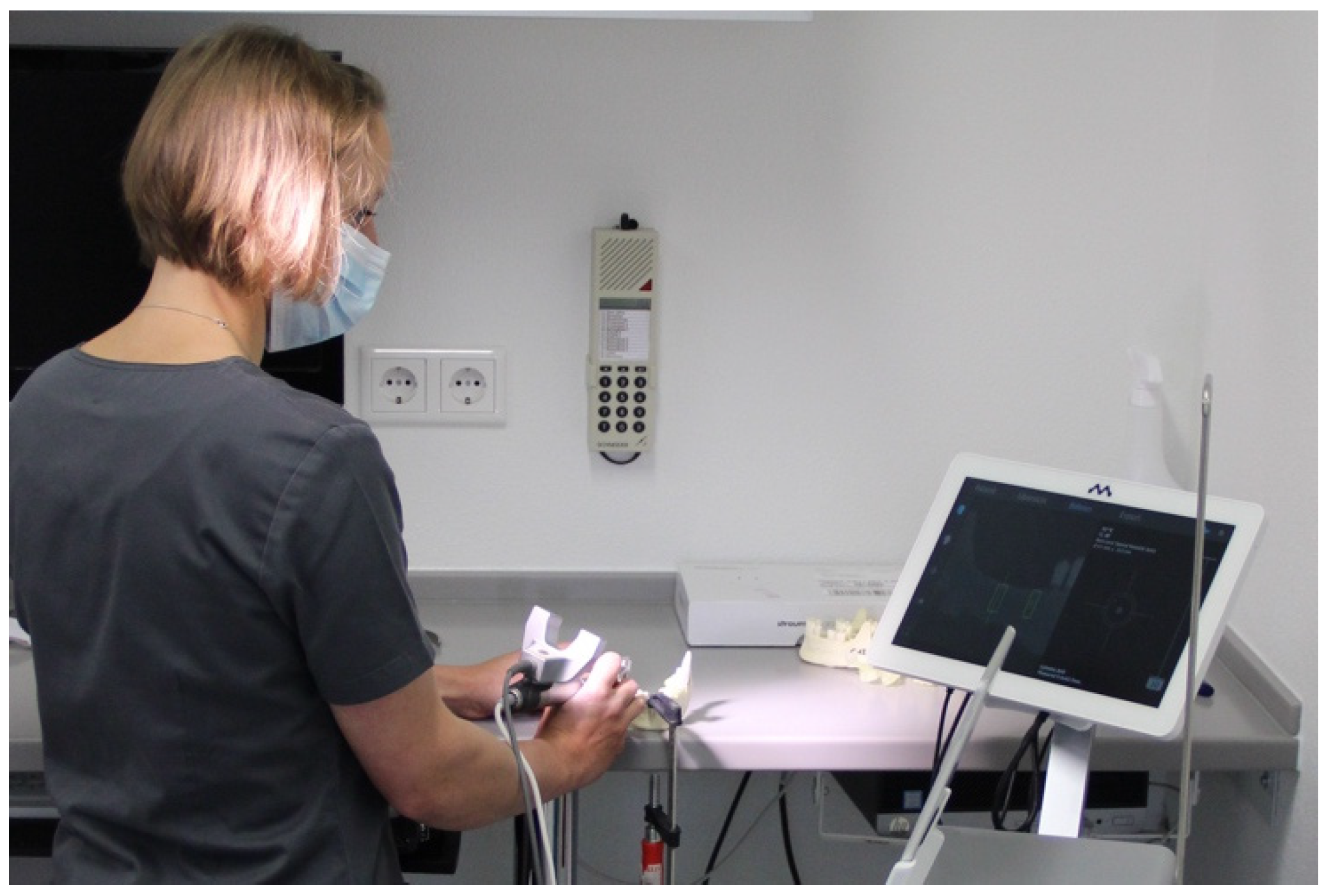
The models were fixed in a stable position on a worktop according to the prescribed protocol (Figure 3). Implantation was performed according to the drilling protocol provided by the implant manufacturer. All model implantations were performed by an experienced dentist (A.K.) using a contra-angle handpiece. The end position of the implant was determined using the DENACAM system’s display. Neither visual control nor readjustment of implant position was performed.
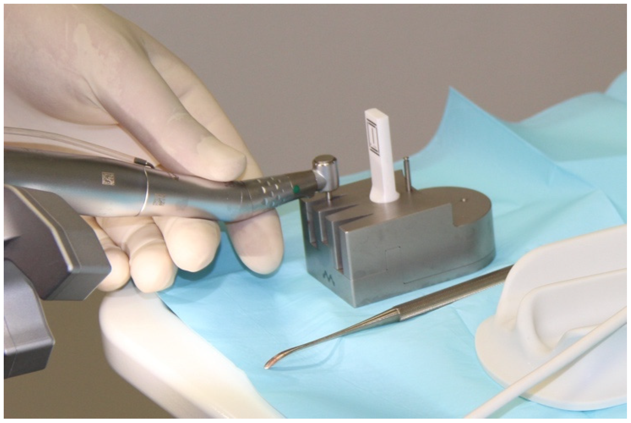
Each drill, including the implant, was automatically registered with a registration instrument before its use (Figure 4). Each drill was inserted in the surgical contra-angle handpiece and placed in a registration block with the marker for automatic registration. The dimensions of the drill were measured. This measurement was compared to the manufacturer’s specifications. This procedure was performed each time the drill was changed to provide a system with precise information on the length and diameter of the drill being used.

2.2. Process Chains

CBCT with a marker and intraoral digitization without a marker (A): a prefabricated holder of the reference marker (DENATRAY, Mininavident, Liestal, Switzerland) was attached to the model with a synthetic thermoplastic material (DENABEADS, Mininavident, Liestal, Switzerland). It was positioned counter-laterally to the implantation region within regions 36 and 37. The marker, a plate made of zirconium oxide ceramic with defined characteristics, was inserted into the tray. The model was positioned with the marker placed on a holder in a digital volume tomograph (CBCT, Gendex CB500, Gendex Dental Systems, Des Plaines, IL, USA). The CBCTs were performed with a standardized resolution of 0.2 voxels. After CBCT was performed, the tray holder was removed and intraoral digitization of the model was performed using a Trios 3 scanner (3Shape A/S, Copenhagen, Denmark). For implant planning, CBCT and intraoral digitization of the model were read into the planning software. During model implantation, the holder with the marker was repositioned in the same place on the model teeth.
CBCT without a marker and intraoral digitization with and without a marker (B_1): a CBCT was produced from the model without the use of a reference marker using the settings described in process A. Intraoral digitization of the jaw was carried out. Once intraoral digitization was complete, a holder with the marker was placed in the same manner described in process A. A subsequent intraoral digitization was created with the holder and marker in place. For implant planning, the CBCT image and intraoral digitization were input into the planning software without a marker and with a marker. During model implantation, the holder and marker were in place.
CBCT without a marker and conventional impression and extraoral digitization with and without a marker (B_2): this approach is a variant of process B_1 that uses the more conventional approach of an alginate impression of the jaw (Blueprint cremix, Dentsply DeTrey, Constance, Germany) instead of intraoral digitization. A model was constructed from a super hard stone in the dental laboratory. The model was then scanned in a laboratory scanner (E4, 3Shape A/S, Copenhagen, Denmark) with and without an attached marker. The CBCT image and placement of the marker were performed as described above. For implant planning, the CBCT image and extraoral digitization of the plaster model were input into the planning software with and without markers. During model implantation, the holder and marker were in place.
CBCT without a marker and intraoral digitization without a marker (C): a CBCT image and intraoral digitization of the jaw were each performed without a reference marker. The resulting datasets were used for implant planning. After the planning was complete, a 3D object representing a holder for the reference marker was inserted into the planning. The object was placed in the contralateral position to the implant region, in regions 34–36, above the teeth. A reference marker holder that could be securely attached to the teeth in quadrant III was made using the drill templates. The design data of the marker templates were sent to an in-house dental laboratory. All marker templates were created by a dental technician using a 3D printer (Version 3, Formlabs Inc., Somerville, MA, USA). The templates were cleaned and post-cured according to the manufacturer’s instructions. During model implantation, the printed holder and marker were in place.

2.3. Registering the Implant Position

After implantation, the scan bodies were screwed onto the two implants. The models were then optically digitized using a high-precision laboratory scanner (E4, 3Shape A/S, Copenhagen, Denmark) and a surface dataset was generated and saved as a standard tessellation language (STL) file. These datasets were integrated into the original digital plans for the evaluation.
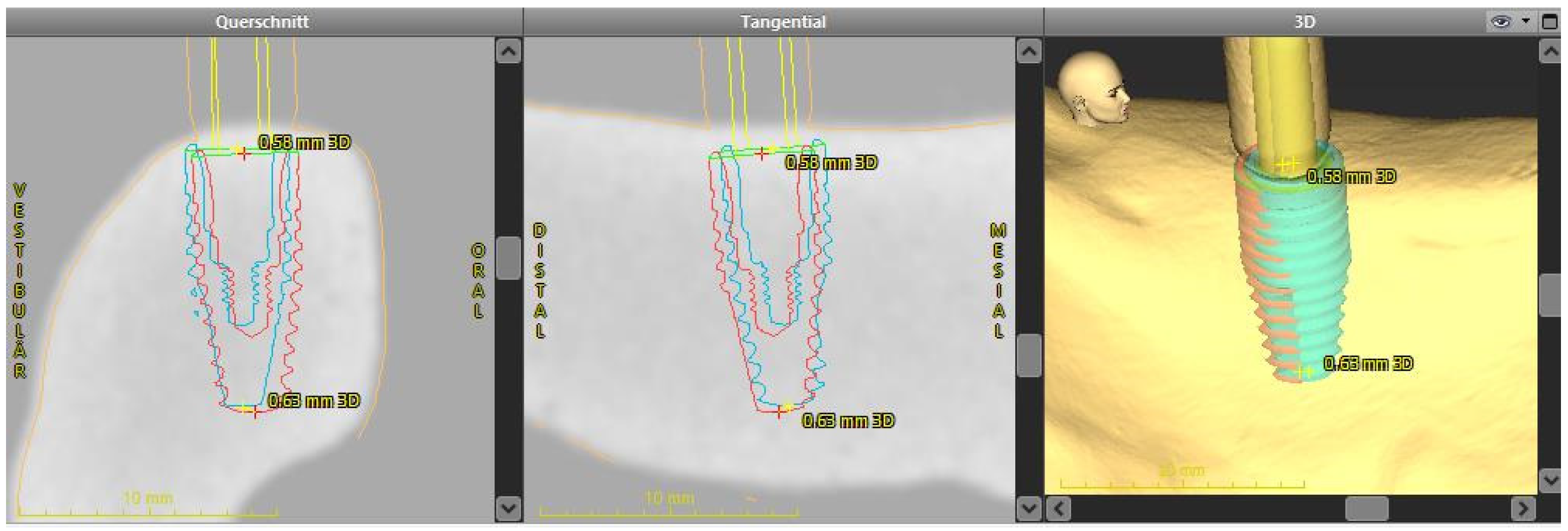
The automated surface best-fit matching using the iterative closest point algorithm in the treatment evaluation mode of the coDiagnostix software was used to overlay the preoperative CBCT with the postoperative lab scans (Figure 5). The overlay and evaluation were performed by a dentist (M.W.) who was not involved in the planning or implant placement.

2.4. Analysis of the Implant Position

The metric analysis included the following measurements:
  • 3D deviation: the three-dimensional deviation of the midpoints between implant planning and the clinically-achieved implant position, measured at the implant shoulder and apex (corresponding to the Euclidean distance).
  • Apico-coronal deviation (height difference): vertical spatial offset measured at the center of the implant shoulder.
  • Axis deviation: Angular deviation of the implant axes between the planned and clinically-achieved implant positions.
  • The two-dimensional deviations in the mesio-distal and bucco-lingual directions were measured at the implant shoulder and at the implant axis.

2.5. Statistical Analysis

Variables are described as means with standard deviations, 95% confidence intervals (CIs), and minimum and maximum values. The Shapiro–Wilk test was used to determine the normality of the distribution of the data. The groups were compared using the analysis of variance or Kruskal–Wallis tests as appropriate. Tukey’s post-hoc test was performed for normally-distributed data, and the Mann–Whitney U-test was used to compare data without normal distribution. Post-hoc tests were used to identify significant differences between the groups.
All statistical analyses were conducted using SPSS® Statistics version 27 (IBM Corp. Released 2020, Armonk, NY, USA). Statistical significance was set at p < 0.05.

3. Results

A total of 120 implants in 60 oral models were evaluated. The coronal 3D deviation was significantly different between the different process chains (p < 0.05).
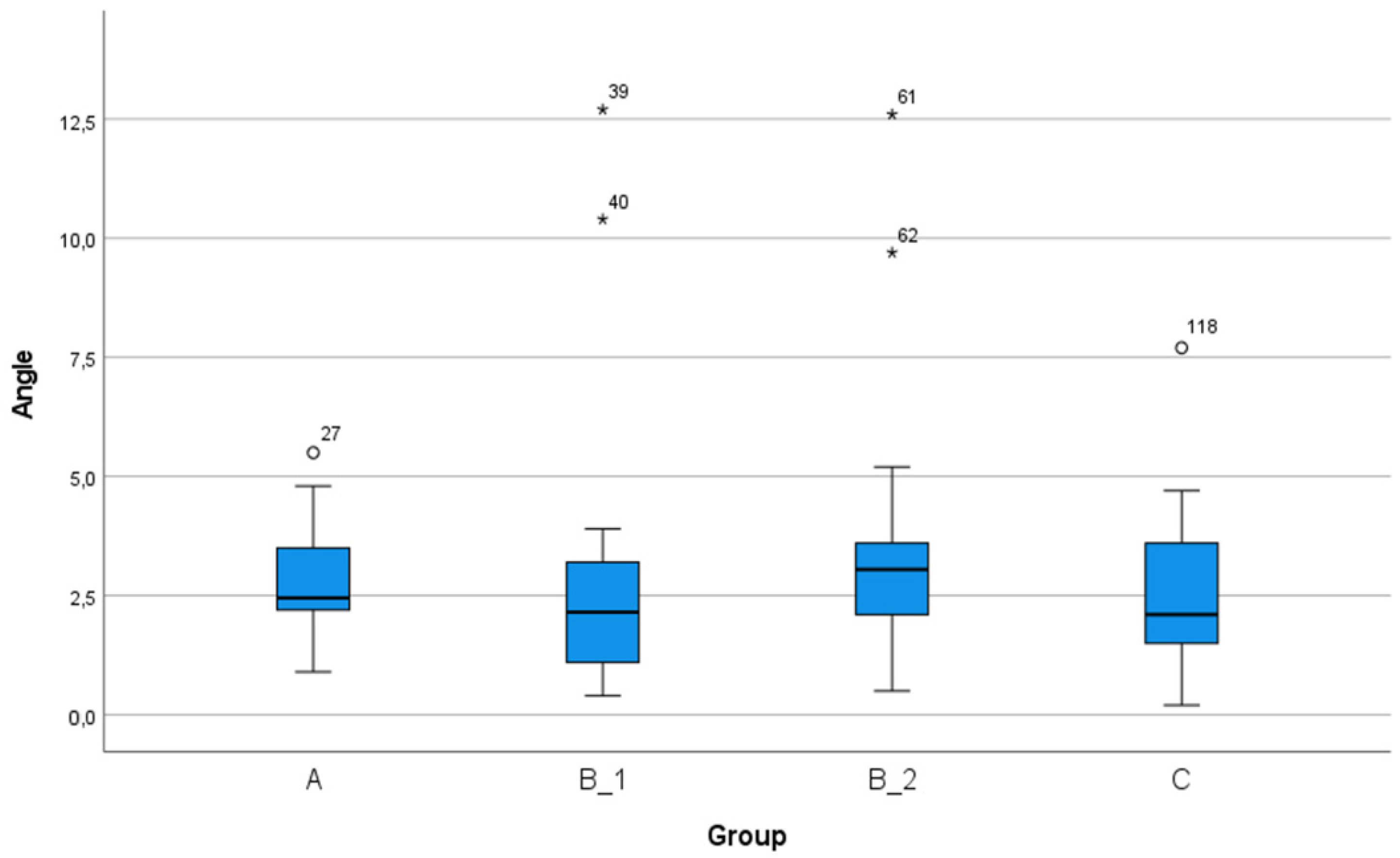
The mean 3D deviation at the implant shoulder of all 120 implantations was 1.53 mm (95% CI: 1.40–1.66 mm). The mean angular deviation was 2.88° (95% CI: 2.51–3.25°). The data for all measured values are shown in Table 2.
There were no significant differences in the positional deviations between implants in region 45 and implants in region 47 (Table 2).
The accuracy was different between the four process chains (Table 3). The workflow had no effect on the angular deviation (F (3, 116) = 1.003; p = 0.394), coronal mesiodistal deviation (F (3, 116) = 0.386; p = 0.763), apical mesiodistal deviation (F (3, 116) = 0.701; p = 0.553), coronal horizontal deviation (F (3, 116) = 1.068; p = 0.365), or apical horizontal deviation (F (3, 116) = 1.228; p = 0.303).
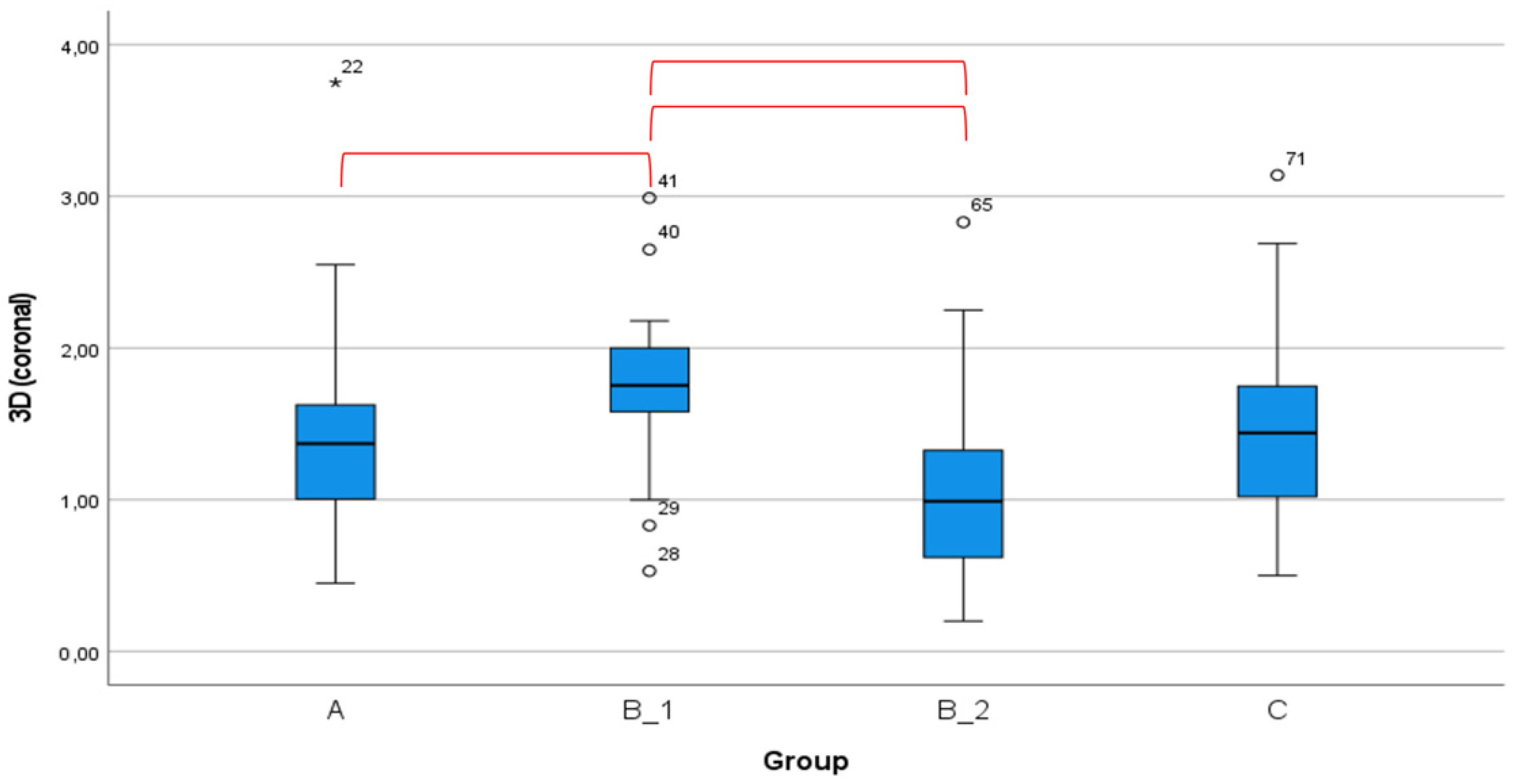
Overall, process chain B_1 resulted in the greatest deviations (Table 4). The mean 3D deviation at the implant shoulder resulting from process chain B_1 (1.85 ± 0.52 mm) was significantly greater than that achieved by process chains A (1.40 ± 0.65 mm), B_2 (1.48 ± 0.92 mm), and C (1.39 ± 0.59 mm). The mean bucco-lingual deviation measured at the shoulder resulting from process chain B_1 (1.47 ± 0.65 mm) was also significantly greater than that achieved by process chains A (0.60 ± 0.48 mm), B_2 (0.91 ± 0.75 mm), and C (0.95 ± 0.53 mm).
There were no significant differences in angular deviation between any of the four process chains (Figure 6). The global 3D deviation measured at the coronal end of the implant was significantly different between process chain B_1 and process chains A, B_2, and C, as shown in Figure 7.

4. Discussion

No significant differences were found between the implant regions. In contrast, the workflow showed significant differences in various parameters. The position of the reference marker affected the accuracy of the implant position. The in vitro examination showed that precise implantation is possible with the dynamic navigation system used in this study.
To date, few in vitro studies have examined the accuracy of implant positions achieved using dynamic navigation. The first reports were published in 2005 [24,26,31], with subsequent publications nearly 10 years later [32,33,34,35,36,37]. Different tracking systems were examined in each of these studies. The reference markers were partially distributed at a large distance from the patient and later were included in the patient’s field of vision. In this study, the markers were placed intraorally to reduce the complexity of the structure and to achieve a setting that is adapted to the requirements of oral surgery.
The mean angular deviation in the present study was 2.88 ± 2.03°. These values show a high level of precision compared to angular deviations reported in previous studies that ranged from 1.09 ± 0.55° [37] to 12.37 ± 4.18° [32]. The unweighted mean value from the studies mentioned above is 4.4°. In this study, the angular deviation was not affected by the process chain or the implant region.
The deviation at the implant exit point has prosthetic importance as inclined implant axes make designing the proximal contacts difficult in cases where individual abutments are not used. In particular, the exit point of the implant directly affects the esthetic results [38]. The mean value of the global 3D deviation at the coronal end of the implant in this study was 1.53 ± 0.70 mm, which is more accurate than the previously-reported values of 0.41 ± 0.12 mm to 1.58 ± 0.80 mm [29]. In this study, the mean mesio-distal deviation was 0.70 ± 0.59 mm and the mean bucco-lingual deviation was 0.98 ± 0.68 mm, which are consistent with the previously reported results of lineal deviations of 0.33 ± 0.19 mm to 3.03 ± 1.81 mm [29]. In this study, the height offset of the 3D-deviation is significant. The final horizontal position was achieved using the navigation system display, and subsequent corrections were not made. The height of the implant in relation to the crestal bone can typically be verified and corrected intraoperatively if the implant planning includes a sufficient safety distance in the axial direction [39].
The subgroup analysis of the implant regions revealed that the distance between the implant and the marker had no significant influence on the accuracy between the planned and clinically-achieved implant positions. The bucco-lingual deviations varied the most between process chains. In this study, the bucco-lingual deviation was affected by the differences in the process chains.
Various factors that influence the accuracy of static navigation have been reported including template design, template positioning and fixation, and surgical access (open vs. closed) [40]. However, the type of implant can affect the accuracy of implantation [41]. In this study, a conical bone-level implant was used in each implantation. Therefore, it is not clear whether the accuracy of implant placement is influenced by the macrodesign of the implant or the drill sequence. These factors may be clinically relevant. To avoid possible uncontrolled co-factors, only one implant system was used in this study. However, the results of an in vitro study cannot be used to directly support clinical use. For example, factors such as bone density, bone anatomy, residual teeth, mouth opening, and patient movements may also affect the accuracy of the implant position and are not accounted for in in vitro studies. In addition, the placement of the marker is better controlled on models than with patients. In this study, only one standard mandible position, the unilateral free-end position of the mandible, was investigated. The intraoral fixation of the reference marker in cases of significantly reduced residual dentition or complete edentulism has not yet been described.
Mediavilla-Guzmán et al. examined the differences in accuracy between a static and dynamic approach in an in vitro study and reported that only the angular deviation was significantly different between the two approaches (static approach: 2.95 ± 1.48°; dynamic approach: 4.00 ± 1.41°) [35]. In another in vitro study that compared dynamic and static methods, each accuracy parameter that was measured was found to be significantly different, with the dynamic system achieving less accuracy; however, the deviation values were much higher than those found in this study [32].
The experience of the surgeon has a minor influence on the accuracy achieved with a static approach [42]. However, the experience of the surgeon has been reported as an influencing factor when dynamic navigation is used [36]. In this study, the experience of the surgeon was found to play a minor role in the accuracy of the implantation. Implant osteotomy can be performed under optimized conditions. Clinical studies are necessary to investigate the effect of the experience and skill of the surgeon on accuracy and the learning curve. Therefore, when comparing systems, the difficulty of using the system in clinical practice should be examined in addition to the accuracy of the system.
The transferability of in vitro results to clinical practice has yet to be proven for the dynamic system presented here. In a systematic review of static navigation, significant differences were found between in vitro and clinical studies, including differences in the apical horizontal deviation and the angular deviation [43]. Similar results were reported in a meta-analysis by Schneider et al. [44]. Factors affecting the transferability of these results to a clinical setting include the patient’s ability to open the mouth, patient movements, or a restricted view of the operating field [45].
In contrast to static navigation, relatively few clinical studies regarding dynamic navigation have been published to date [46,47,48,49,50,51,52]. These studies have reported heterogeneous factors affecting accuracy. Different dynamic navigation systems, implant planning programs, and implants were used in these previous studies, resulting in mean angular deviations between 2.26 ± 1.62° and 6.46 ± 3.95°. The previously reported 3D deviations at the coronal end of the implant were between 0.67 ± 0.29 mm and 1.37 ± 0.55 mm.
Previous studies have reported similar average deviation values obtained with dynamic and static navigation systems [11,43,45]. However, the accuracy varies greatly in these clinical and in vitro studies. More studies are required to determine whether this is due to the specific dynamic navigation system. In addition, some systems have only been evaluated by one surgical team. The accuracy and feasibility of these systems for clinical use must be examined in future studies. To assess the benefits of this procedure for the patient, the operation time, surgical difficulty, and cost must also be evaluated.

5. Conclusions

The in vitro study showed that a sufficiently precise implantation is possible with the dynamic navigation system used in this study. The workflow influenced the implant placement accuracy. Accuracy is dependent on the navigation system being used. Clinical studies are needed to verify the results of this study and to assess the clinical feasibility of dynamic navigation.

Author Contributions

S.S., A.K., and C.E. contributed to the conception and design of the study, data analysis and interpretation, and drafted the manuscript; A.K. and M.W. contributed to data acquisition, analysis, and interpretation of the data and critically revised and drafted the manuscript; S.S. and R.L. contributed to the statistical analysis, data analysis, and data interpretation; R.L. critically revised the manuscript and drafted the manuscript. All authors gave final approval and agreed to be accountable for all aspects of the work. All authors have read and agreed to the published version of the manuscript.

Funding

This research received no external funding.

Institutional Review Board Statement

Not applicable.

Informed Consent Statement

Not applicable.

Data Availability Statement

Not applicable.

Acknowledgments

We would like to thank Institut Straumann AG (Basel, Switzerland) for providing the implant materials. We would also like to thank DentalWings (Chemnitz, Germany) for allowing us to use the implant planning and evaluation program free of charge.

Conflicts of Interest

The authors declare no conflict of interest.

References

  1. D’Haese, J.; Ackhurst, J.; Wismeijer, D.; De Bruyn, H.; Tahmaseb, A. Current state of the art of computer-guided implant surgery. Periodontology 2000 2016, 73, 121–133. [Google Scholar] [CrossRef] [PubMed]
  2. Bosshardt, D.D.; Chappuis, V.; Buser, D. Osseointegration of titanium, titanium alloy and zirconia dental implants: Current knowledge and open questions. Periodontology 2000 2017, 73, 22–40. [Google Scholar] [CrossRef]
  3. Albrektsson, T.; Chrcanovic, B.; Östman, P.-O.; Sennerby, L. Initial and long-term crestal bone responses to modern dental implants. Periodontology 2000 2016, 73, 41–50. [Google Scholar] [CrossRef] [PubMed]
  4. Romanos, G.E.; Delgado-Ruiz, R.; Sculean, A. Concepts for prevention of complications in implant therapy. Periodontology 2000 2019, 81, 7–17. [Google Scholar] [CrossRef] [PubMed]
  5. Al Amri, M.D. Influence of interimplant distance on the crestal bone height around dental implants: A systematic review and meta-analysis. J. Prosthet. Dent. 2016, 115, 278–282. [Google Scholar] [CrossRef]
  6. Staubli, N.; Walter, C.; Schmidt, J.C.; Weiger, R.; Zitzmann, N.U. Excess cement and the risk of peri-implant disease—A systematic review. Clin. Oral Implant. Res. 2017, 28, 1278–1290. [Google Scholar] [CrossRef]
  7. Garber, D.A.; Belser, U.C. Restoration-driven implant placement with restoration-generated site development. Compend. Contin. Educ. Dent. (Jamesburg N.J. 1995) 1995, 16, 796–798. [Google Scholar]
  8. Vercruyssen, M.; Van De Wiele, G.; Teughels, W.; Naert, I.; Jacobs, R.; Quirynen, M. Implant- and patient-centred outcomes of guided surgery, a 1-year follow-up: An RCT comparing guided surgery with conventional implant placement. J. Clin. Periodontol. 2014, 41, 1154–1160. [Google Scholar] [CrossRef]
  9. Hultin, M.; Svensson, K.G.; Trulsson, M. Clinical advantages of computer-guided implant placement: A systematic review. Clin. Oral Implant. Res. 2012, 23, 124–135. [Google Scholar] [CrossRef]
  10. Wismeijer, D.; Joda, T.; Flügge, T.; Fokas, G.; Tahmaseb, A.; Bechelli, D.; Bohner, L.; Bornstein, M.; Burgoyne, A.; Caram, S.; et al. Group 5 ITI Consensus Report: Digital technologies. Clin. Oral Implant. Res. 2018, 29, 436–442. [Google Scholar] [CrossRef]
  11. Tahmaseb, A.; Wu, V.; Wismeijer, D.; Coucke, W.; Evans, C. The accuracy of static computer-aided implant surgery: A systematic review and meta-analysis. Clin. Oral Implant. Res. 2018, 29, 416–435. [Google Scholar] [CrossRef] [Green Version]
  12. Al Yafi, F.; Camenisch, B.; Al-Sabbagh, M. Is Digital Guided Implant Surgery Accurate and Reliable? Dent. Clin. N. Am. 2019, 63, 381–397. [Google Scholar] [CrossRef] [PubMed]
  13. Gargallo-Albiol, J.; Barootchi, S.; Salomó-Coll, O.; Wang, H.-L. Advantages and disadvantages of implant navigation surgery. A systematic review. Ann. Anat. Anat. Anz. 2019, 225, 1–10. [Google Scholar] [CrossRef] [PubMed]
  14. Tahmaseb, A.; Wismeijer, D.; Coucke, W.; Derksen, W. Computer Technology Applications in Surgical Implant Dentistry: A Systematic Review. Int. J. Oral Maxillofac. Implant. 2014, 29, 25–42. [Google Scholar] [CrossRef] [PubMed] [Green Version]
  15. Gjelvold, B.; Mahmood, D.J.H.; Wennerberg, A. Accuracy of surgical guides from 2 different desktop 3D printers for computed tomography-guided surgery. J. Prosthet. Dent. 2019, 121, 498–503. [Google Scholar] [CrossRef] [PubMed]
  16. Henprasert, P.; Dawson, D.V.; El-Kerdani, T.; Song, X.; Couso-Queiruga, E.; Holloway, J.A. Comparison of the Accuracy of Implant Position Using Surgical Guides Fabricated by Additive and Subtractive Techniques. J. Prosthodont. 2020, 29, 534–541. [Google Scholar] [CrossRef] [PubMed] [Green Version]
  17. Pieralli, S.; Spies, B.C.; Hromadnik, V.; Nicic, R.; Beuer, F.; Wesemann, C. How Accurate Is Oral Implant Installation Using Surgical Guides Printed from a Degradable and Steam-Sterilized Biopolymer? J. Clin. Med. 2020, 9, 2322. [Google Scholar] [CrossRef] [PubMed]
  18. Liang, Y.; Yuan, S.; Huan, J.; Zhang, Y.; Fang, C.; Li, J. In Vitro Experimental Study of the Effect of Adjusting the Guide Sleeve Height and Using a Visual Direction-Indicating Guide on Implantation Accuracy. J. Oral Maxillofac. Surg. 2019, 77, 2259–2268. [Google Scholar] [CrossRef]
  19. Tallarico, M.; Martinolli, M.; Kim, Y.-J.; Cocchi, F.; Meloni, S.M.; Alushi, A.; Xhanari, E. Accuracy of Computer-Assisted Template-Based Implant Placement Using Two Different Surgical Templates Designed with or without Metallic Sleeves: A Randomized Controlled Trial. Dent. J. 2019, 7, 41. [Google Scholar] [CrossRef] [Green Version]
  20. Kuhl, S.; Payer, M.; Zitzmann, N.U.; Lambrecht, J.T.; Filippi, A. Technical accuracy of printed surgical templates for guided implant surgery with the coDiagnostiX software. Clin. Implant. Dent. Relat. Res. 2015, 17 (Suppl. 1), e177–e182. [Google Scholar] [CrossRef]
  21. Schnutenhaus, S.; Edelmann, C.; Rudolph, H.; Luthardt, R.G. Retrospective study to determine the accuracy of template-guided implant placement using a novel nonradiologic evaluation method. Oral Surg. Oral Med. Oral Pathol. Oral Radiol. 2016, 121, e72–e79. [Google Scholar] [CrossRef] [PubMed]
  22. Vercruyssen, M.; Fortin, T.; Widmann, G.; Jacobs, R.; Quirynen, M. Different techniques of static/dynamic guided implant surgery: Modalities and indications. Periodontology 2000 2014, 66, 214–227. [Google Scholar] [CrossRef]
  23. Du, Y.; Wangrao, K.; Liu, L.; Liu, L.; Yao, Y. Quantification of Image Artifacts from Navigation Markers in Dynamic Guided Implant Surgery and the Effect on Registration Performance in Different Clinical Scenarios. Int. J. Oral Maxillofac. Implant. 2019, 34, 726–736. [Google Scholar] [CrossRef] [PubMed]
  24. Brief, J.; Edinger, D.; Hassfeld, S.; Eggers, G. Accuracy of image-guided implantology. Clin. Oral Implant. Res. 2005, 16, 495–501. [Google Scholar] [CrossRef]
  25. Hoffmann, J.; Westendorff, C.; Reinert, S.; Gomez-Roman, G. Accuracy of navigation-guided socket drilling before implant installation compared to the conventional free-hand method in a synthetic edentulous lower jaw model. Clin. Oral Implant. Res. 2005, 16, 609–614. [Google Scholar] [CrossRef] [PubMed]
  26. Kramer, F.-J.; Baethge, C.; Swennen, G.; Rosahl, S. Navigated vs. conventional implant insertion for maxillary single tooth replacement. Clin. Oral Implant. Res. 2004, 16, 60–68. [Google Scholar] [CrossRef]
  27. Chen, J.T.-Y. A Novel Application of Dynamic Navigation System in Socket Shield Technique. J. Oral Implant. 2019, 45, 409–415. [Google Scholar] [CrossRef] [Green Version]
  28. Block, M.S.; Emery, R.W. Static or Dynamic Navigation for Implant Placement—Choosing the Method of Guidance. J. Oral Maxillofac. Surg. 2016, 74, 269–277. [Google Scholar] [CrossRef]
  29. Schnutenhaus, S.; Edelmann, C.; Knipper, A.; Luthardt, R. Accuracy of Dynamic Computer-Assisted Implant Placement: A Systematic Review and Meta-Analysis of Clinical and In Vitro Studies. J. Clin. Med. 2021, 10, 704. [Google Scholar] [CrossRef]
  30. Ayoub, A.; Pulijala, Y. The application of virtual reality and augmented reality in Oral & Maxillofacial Surgery. BMC Oral Health 2019, 19, 1–8. [Google Scholar] [CrossRef] [Green Version]
  31. Hoffmann, J.; Westendorff, C.; Schneider, M.; Reinert, S. Accuracy assessment of image-guided implant surgery: An experimental study. Int. J. Oral Maxillofac. Implant. 2005, 20, 382–386. [Google Scholar]
  32. Kang, S.-H.; Lee, J.-W.; Lim, S.-H.; Kim, Y.-H.; Kim, M.-K. Verification of the usability of a navigation method in dental implant surgery: In vitro comparison with the stereolithographic surgical guide template method. J. Cranio Maxillofac. Surg. 2014, 42, 1530–1535. [Google Scholar] [CrossRef] [PubMed]
  33. Kim, S.-G.; Lee, W.-J.; Lee, S.-S.; Heo, M.-S.; Huh, K.-H.; Choi, S.-C.; Kim, T.-I.; Yi, W.-J. An advanced navigational surgery system for dental implants completed in a single visit: An in vitro study. J. Cranio Maxillofac. Surg. 2015, 43, 117–125. [Google Scholar] [CrossRef] [PubMed]
  34. Somogyi-Ganss, E.; Holmes, H.I.; Jokstad, A. Accuracy of a novel prototype dynamic computer-assisted surgery system. Clin. Oral Implant. Res. 2014, 26, 882–890. [Google Scholar] [CrossRef] [PubMed]
  35. Mediavilla Guzman, A.; Riad Deglow, E.; Zubizarreta-Macho, A.; Agustin-Panadero, R.; Hernandez Montero, S. Accuracy of Computer-Aided Dynamic Navigation Compared to Computer-Aided Static Navigation for Dental Implant Placement: An In Vitro Study. J. Clin. Med. 2019, 8, 2123. [Google Scholar] [CrossRef] [Green Version]
  36. Pellegrino, G.; Bellini, P.; Cavallini, P.F.; Ferri, A.; Zacchino, A.; Taraschi, V.; Marchetti, C.; Consolo, U. Dynamic Navigation in Dental Implantology: The Influence of Surgical Experience on Implant Placement Accuracy and Operating Time. An in Vitro Study. Int. J. Environ. Res. Public Health 2020, 17, 2153. [Google Scholar] [CrossRef] [Green Version]
  37. Emery, R.W.; A Merritt, S.; Lank, K.; Gibbs, J.D. Accuracy of Dynamic Navigation for Dental Implant Placement–Model-Based Evaluation. J. Oral Implant. 2016, 42, 399–405. [Google Scholar] [CrossRef] [PubMed]
  38. Forna, N.; Agop-Forna, D. Esthetic aspects in implant-prosthetic rehabilitation. Med. Pharm. Rep. 2019, 92, S6–S13. [Google Scholar] [CrossRef]
  39. Cosola, S.; Marconcini, S.; Boccuzzi, M.; Fabris, G.B.M.; Covani, U.; Peñarrocha-Diago, M.; Peñarrocha-Oltra, D. Radiological Outcomes of Bone-Level and Tissue-Level Dental Implants: Systematic Review. Int. J. Environ. Res. Public Health 2020, 17, 6920. [Google Scholar] [CrossRef] [PubMed]
  40. Zhou, W.; Liu, Z.; Song, L.; Kuo, C.-L.; Shafer, D.M. Clinical Factors Affecting the Accuracy of Guided Implant Surgery—A Systematic Review and Meta-analysis. J. Evid. Based Dent. Pr. 2018, 18, 28–40. [Google Scholar] [CrossRef]
  41. Yeung, M.; Abdulmajeed, A.; Carrico, C.K.; Deeb, G.R.; Bencharit, S. Accuracy and precision of 3D-printed implant surgical guides with different implant systems: An in vitro study. J. Prosthet. Dent. 2020, 123, 821–828. [Google Scholar] [CrossRef]
  42. Cassetta, M.; Altieri, F.; Giansanti, M.; Bellardini, M.; Brandetti, G.; Piccoli, L. Is there a learning curve in static computer-assisted implant surgery? A prospective clinical study. Int. J. Oral Maxillofac. Surg. 2020, 49, 1335–1342. [Google Scholar] [CrossRef]
  43. Bover-Ramos, F.; Viña-Almunia, J.; Cervera-Ballester, J.; Peñarrocha-Diago, M.; García-Mira, B. Accuracy of Implant Placement with Computer-Guided Surgery: A Systematic Review and Meta-Analysis Comparing Cadaver, Clinical, and In Vitro Studies. Int. J. Oral Maxillofac. Implant. 2018, 33, 101–115. [Google Scholar] [CrossRef] [PubMed]
  44. Schneider, D.; Marquardt, P.; Zwahlen, M.; Jung, R.E. A systematic review on the accuracy and the clinical outcome of computer-guided template-based implant dentistry. Clin. Oral Implant. Res. 2009, 20, 73–86. [Google Scholar] [CrossRef] [PubMed] [Green Version]
  45. Jung, R.E.; Schneider, D.; Ganeles, J.; Wismeijer, D.; Zwahlen, M.; Hämmerle, C.H.F.; Tahmaseb, A. Computer technology applications in surgical implant dentistry: A systematic review. Int. J. Oral Maxillofac. Implant. 2009, 24, 25–42. [Google Scholar]
  46. Aydemir, C.A.; Arısan, V. Accuracy of dental implant placement via dynamic navigation or the freehand method: A split-mouth randomized controlled clinical trial. Clin. Oral Implant. Res. 2020, 31, 255–263. [Google Scholar] [CrossRef]
  47. Block, M.S.; Emery, R.W.; Cullum, D.R.; Sheikh, A. Implant Placement Is More Accurate Using Dynamic Navigation. J. Oral Maxillofac. Surg. 2017, 75, 1377–1386. [Google Scholar] [CrossRef]
  48. Block, M.S.; Emery, R.W.; Lank, K.; Ryan, J. Implant Placement Accuracy Using Dynamic Navigation. Int. J. Oral Maxillofac. Implant. 2017, 32, 92–99. [Google Scholar] [CrossRef]
  49. Kaewsiri, D.; Panmekiate, S.; Subbalekha, K.; Mattheos, N.; Pimkhaokham, A. The accuracy of static vs. dynamic computer-assisted implant surgery in single tooth space: A randomized controlled trial. Clin. Oral Implant. Res. 2019, 30, 505–514. [Google Scholar] [CrossRef]
  50. Pellegrino, G.; Taraschi, V.; Andrea, Z.; Ferri, A.; Marchetti, C. Dynamic navigation: A prospective clinical trial to evaluate the accuracy of implant placement. Int. J. Comput. Dent. 2019, 22, 139–147. [Google Scholar]
  51. Stefanelli, L.V.; DeGroot, B.S.; I Lipton, D.; A Mandelaris, G. Accuracy of a Dynamic Dental Implant Navigation System in a Private Practice. Int. J. Oral Maxillofac. Implant. 2019, 34, 205–213. [Google Scholar] [CrossRef] [PubMed]
  52. Stefanelli, L.V.; Mandelaris, G.A.; Franchina, A.; Pranno, N.; Pagliarulo, M.; Cera, F.; Maltese, F.; De Angelis, F.; Di Carlo, S. Accuracy of Dynamic Navigation System Workflow for Implant Supported Full Arch Prosthesis: A Case Series. Int. J. Environ. Res. Public Health 2020, 17, 5038. [Google Scholar] [CrossRef] [PubMed]
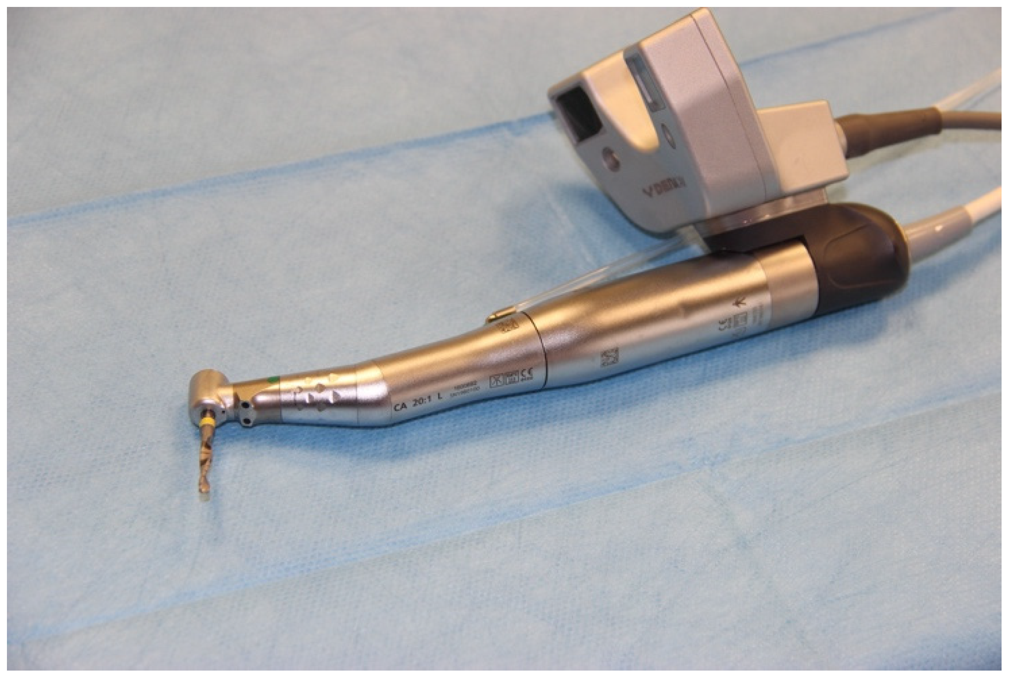
Figure 1. Surgical handpiece with camera attached.
Ijerph 18 03244 g001
Figure 2. Plastic model with fixed marker, in this example a model from Group A.
Ijerph 18 03244 g002
Figure 3. Implementing implantation under standardized laboratory conditions.
Ijerph 18 03244 g003
Figure 4. Registering the drill.
Ijerph 18 03244 g004
Figure 5. Overlay of the planned and actual achieved implant position using the treatment evaluation program function of coDiagnostiX software.
Ijerph 18 03244 g005
Figure 6. The angular deviations achieved by each process chain. No significant differences were observed between the process chains. Process chain B_1: CBCT without a reference marker and intraoral digitization with and without a reference marker. Process chain B_2: CBCT without a reference marker and conventional impression and extraoral digitization with and without a reference marker. Process chain C: CBCT without a reference marker and intraoral digitization without a reference marker.
Ijerph 18 03244 g006
Figure 7. The global 3D deviations at the coronal exit point achieved by each process chain. The 3D deviations at the coronal exit point are significantly different between the B-1 process chain and the A, B_2, and C process chains. Statistical significance was determined using the Mann–Whitney U test. The red lines indicate significant group differences.
Ijerph 18 03244 g007
Table 1. Overview of the four different process chains.
Workflow
AB_1B_2C
Data GenerationCBCTCBCT image with marker CBCT imageCBCT imageCBCT image
On the patientIntraoral scanTwo intraoral scans (with and without marker)Alginate impressionIntraoral scan
Virtually Creation of a digital marker template
In the laboratory Two model scans (with and without marker)3D printing of a marker template
Reference marker in surgerySurgery with DenatraySurgery with DenatraySurgery with DenatraySurgery with marker template
Table 2. Deviations between the planned and clinically-achieved implant positions.
Total
n = 60 Models/120 Implants
Region 45
n = 60 Models/60 Implants
Region 47
n = 60 Models/60 Implants
p-Value
Mean (SD)95% CIMin–MaxMean (SD)95% CIMin–MaxMean (SD)95% CIMin–Max
Deviation at implant shoulder (mm)
3D 1.53 (0.70)1.40–1.660.20–4.021.52 (0.64)1.36–1.690.26–4.021.54 (0.77)1.34–1.740.20–3.750.923
Mesio-distal 0.70 (0.59)0.59–0.800.02–3.060.63 (0.57)0.48–0.780.02–2.370.77 (0.62)0.61–0.930.04–3.060.208
Bucco-lingual0.98 (0.68)0.86–1.110.00–2.811.09 (0.66)0.91–1.250.00–2.520.87 (0.70)0.71–1.070.00–2.810.116
Apico-coronal0.57 (0.50)0.48–0.670.00–2.340.48 (0.43)0.37–0.60)0.00–2.170.66 (0.54)0.51–0.800.00–2.340.059
Deviation at implant apex (mm)
3D 1.79 (0.80)1.64–1.940.29–4.051.81 (0.74)1.78–2.000.29–4.051.77 (0.86)1.54–1.990.29–3.740.766
Mesio-distal0.81 (0.70)0.68–0.930.01–3.730.80 (0.71)0.62–0.980.04–3.730.82 (0.69)0.64–1.000.01–3.260.890
Bucco-lingual1.25 (0.75)1.12–1.390.01–3.101.36 (0.66)1.19–1.530.20–2.791.15 (0.83)0.93–1.360.01–3.100.126
Apico-coronal0.58 (0.50)0.49–0.670.00–2.350.50 (0.43)0.39–0.610.00–2.190.66 (0.55)0.52–0.810.00–2.350.068
Angular deviation (°)2.88 (2.03)2.51–3.250.20–12.702.87 (2.22)2.30–3.440.20–12.702.89 (1.83)2.41–3.360.40–10.400.964
Table 3. Deviations between the planned and clinically-achieved implant positions.
Process Chain A
n = 15 Models/30 Implants
Process Chain B_1
n = 15 Models/30 Implants
Process Chain B_2
n = 15 Models/30 Implants
Process Chain C
n = 15 Models/30 Implants
p-Value
Mean (SD)95% CIMin–MaxMean (SD)95% CIMin–MaxMean (SD)95% CIMin–MaxMean (SD)95% CIMin–Max
Deviation at implant shoulder (mm)
3D 1.40 (0.65)1.16–1.640.41–3.751.85 (0.52)1.66–2.040.53–2.991.48 (0.92)1.14–1.830.20–4.021.39 (0.59)1.17–1.610.50–3.140.034
Mesio-distal 0.80 (0.63)0.55–1.040.06–3.060.64 (0.50)0.45–0.830.04–1.700.68 (0.66)0.44–0.930.02–2.370.67 (0.56)0.46–0.880.04–2.630.763
Bucco-lingual0.60 (0.48)0.42–0.780.06–1.911.47 (0.65)1.47–1.720.14–2.60.91 (0.75)0.63–1.190.00–2.810.95 (0.53)0.76–1.150.00–1.81<0.005
Apico-coronal0.67 (0.53)0.47–0.870.00–2.100.56 (0.38)0.41–0.70)0.01–1.290.60 (0.65)0.36–0.840.01–2.340.45 (0.37)0.31–0.590.02–1.650.303
Deviation at implant apex (mm)
3D 1.54 (0.72)1.27–1.810.75–3.562.13 (0.62)1.90–2.090.69–3.491.80 (1.06)1.41–2.200.29–4.051.68 (0.65)1.44–1.920.63–3.680.029
Mesio-distal0.80 (0.66)0.55–1.050.04–2.870.67 (0.51)0.48–0.860.04–1.800.83 (0.88)0.50–1.160.04–3.730.93 (0.70)0.66–1.190.01–3.260.553
Bucco-lingual0.86 (0.59)0.64–1.080.01–2.411.82 (0.68)1.57–2.070.08–3.101.23 (0.79)0.93–1.200.12–2.931.10 (0.60)0.88–1.320.18–2.31<0.005
Apico-coronal0.69 (0.53)0.49–0.890.00–2.120.57 (0.39)0.42–0.710.01–1.350.62 (0.65)0.38–0.860.01–2.350.45 (0.37)0.31–0.590.00–1.620.303
Angular deviation (°)2.77 (1.06)2.37–3.160.90–5.502.70 (2.61)1.73–3.680.40–12.703.43 (2.44)2.52–3.130.50–12.62.62 (1.60)2.02–3.220.20–7.700.394
p-values were determined using the analysis of variance (ANOVA) test. Process chain A: cone-beam computed tomography (CBCT) with a reference marker and intraoral digitization without a reference marker. Process chain B_1: CBCT without a reference marker and intraoral digitization with and without a reference marker. Process chain B_2: CBCT without a reference marker and conventional impression and extraoral digitization with and without a reference marker. Process chain C: CBCT without a reference marker and intraoral digitization without a reference marker.
Table 4. Comparison of the deviations achieved by each process chain.
A-B_1A-B_2A-CB_1-B_2B_1-CB_2-C
Deviation at implant shoulder (mm)
3D0.001 *0.7220.8730.003 *0.002 *0.844
Mesio-distal0.7470.8870.8490.9920.9971.000
Bucco-lingual<0.001 *0.2200.1250.003 *0.007 *0.992
Apico-coronal0.8000.9370.3030.9880.8350.648
Deviation at implant apex (mm)
3D0.022 *0.5730.9050.3660.1190.929
Mesio-distal0.8840.9980.8970.8050.4810.951
Bucco-lingual<0.001 *0.1470.5020.005 *<0.001 *0.881
Apico-coronal0.7960.9580.2550.9760.7870.536
Angular deviation (degree)0.9990.5900.9920.5130.9980.413
The p-values for the comparisons are shown. The values were compared using Tukey’s test, with the exception of 3D deviations, which were compared using the Mann–Whitney U test. * indicates statistical significance.
Publisher’s Note: MDPI stays neutral with regard to jurisdictional claims in published maps and institutional affiliations.