
Analysis of the Impact Resistance of Toecaps by the Finite Element Method: Preliminary Studies
 , , and
Abstract
:1. Introduction
2. Materials and Methods
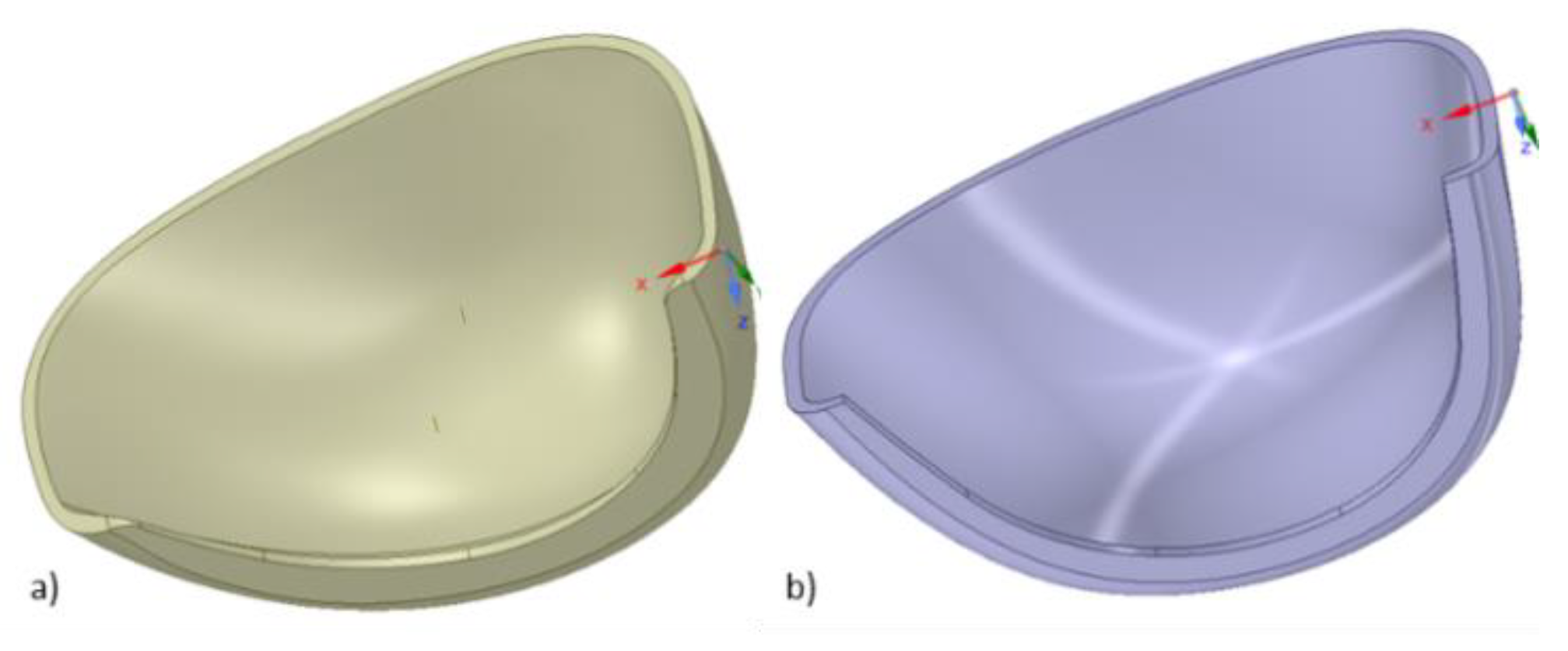
2.1. Geometry Preparation Methodology
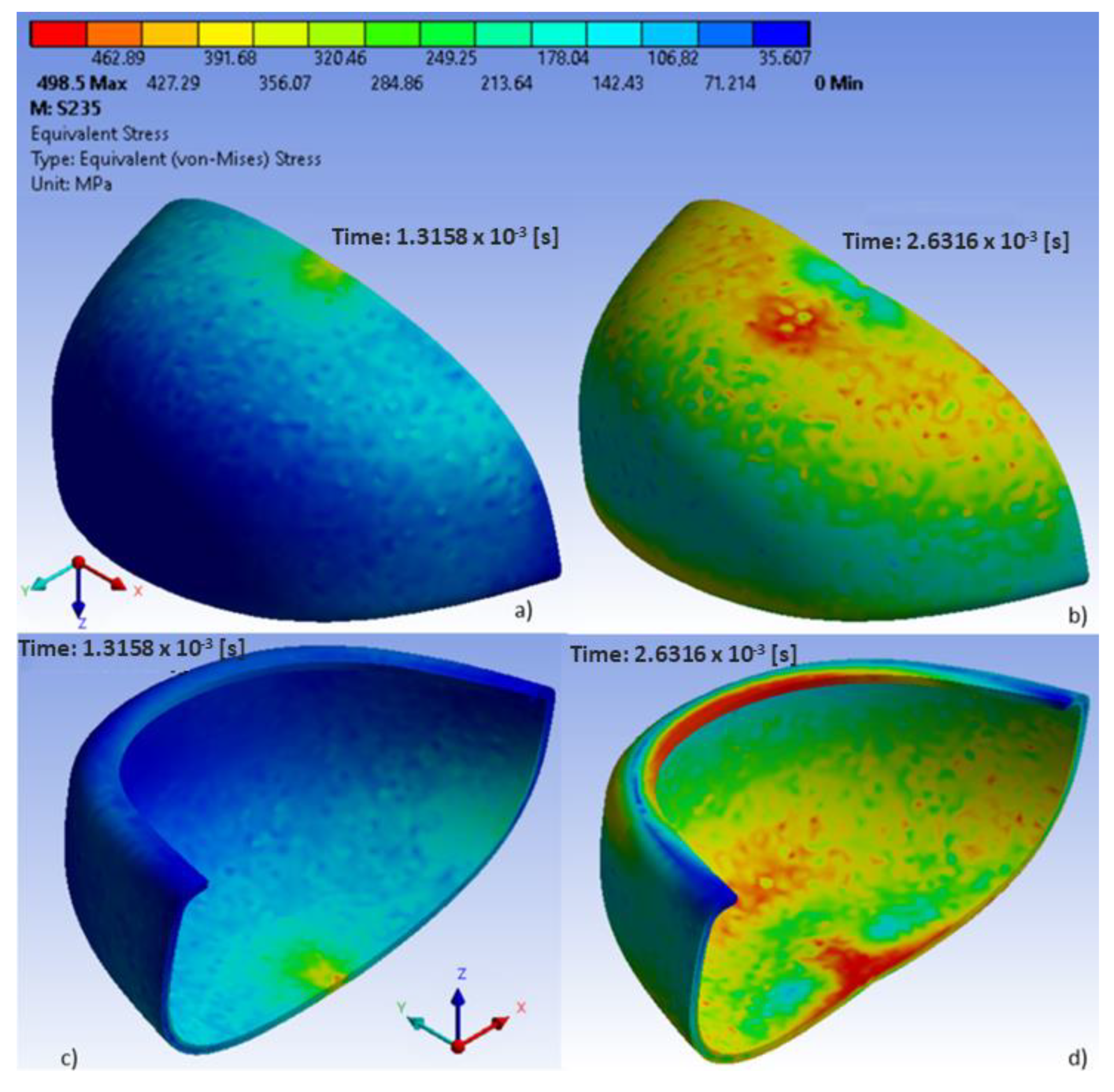
2.2. Johnson–Cook Model and Material Selection
- Lexan—a polycarbonate;
- AISI 10450—a quality heat-treatable non-alloy steel;
- S235—a non-alloy structural steel;
- S355—a high-strength low-alloy structural steel;
- A36—a high-strength low-alloy steel.
3. Analysis of the Impact Resistance of Toecaps by the Finite Element Method
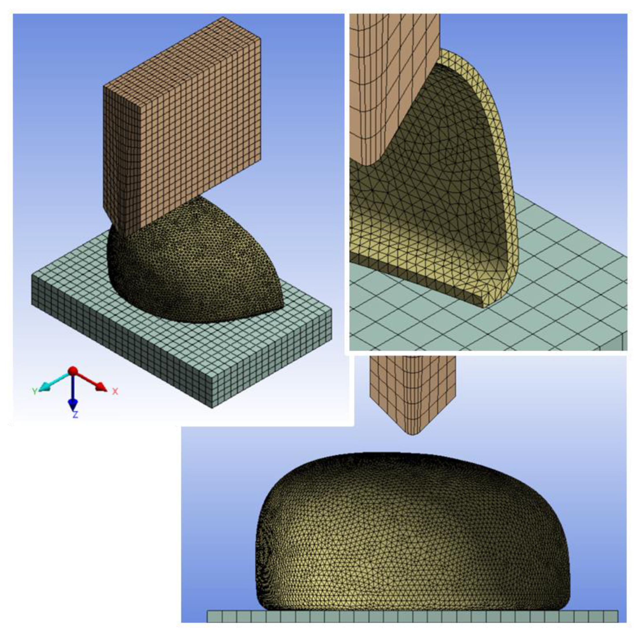
Finite Element Modeling
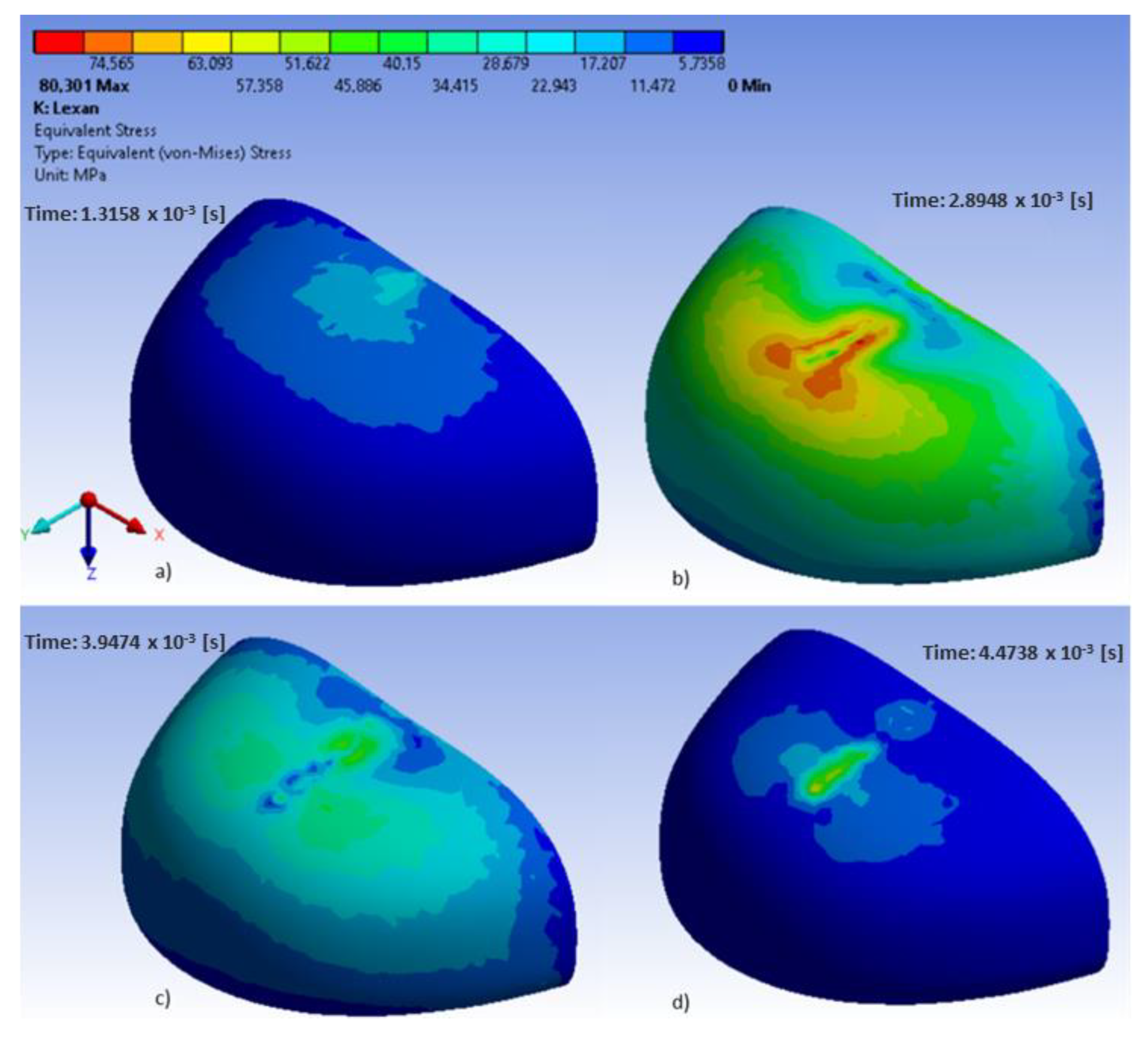
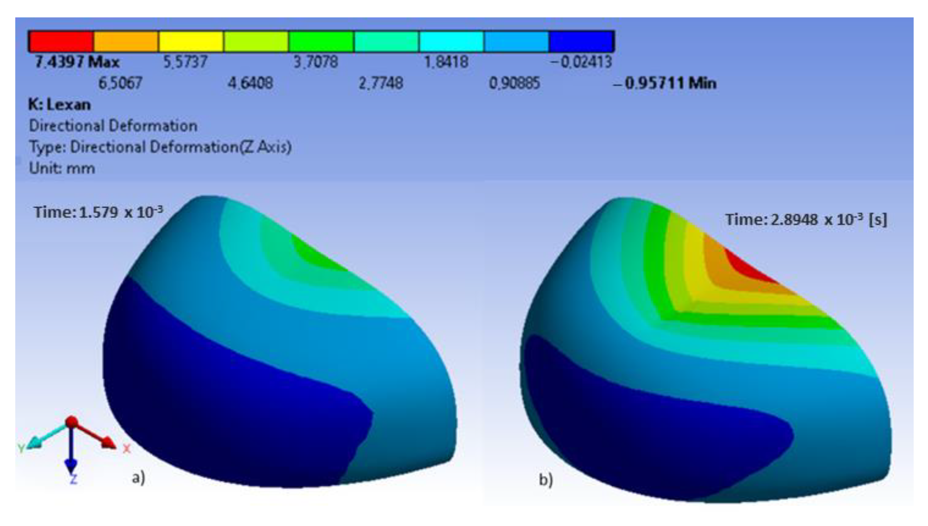
4. Results and Analysis
5. Discussion
6. Conclusions
Author Contributions
Funding
Institutional Review Board Statement
Informed Consent Statement
Data Availability Statement
Conflicts of Interest
References
- Regulation (EU) 2016/425 of the European Paliament and of the Council of 9 March 2016 on Personal Protective Equipment and Repealing Council Directive 89/686/EEC 2016. Available online: https://eur-lex.europa.eu/legal-content/EN/TXT/?uri=CELEX%3A32016R0425 (accessed on 2 September 2022).
- Nakanishi, E.; Tateno, H.; Hishida, Y.; Shibata, K. New Materials Technology for Achieving Both Crashworthiness and Weight Reduction Using Energy-Absorbing Steel with Higher Strain-Rate Sensitivity. SAE Trans. 1998, 107, 680–686. [Google Scholar] [CrossRef]
- EN ISO 22568:2019; Foot and Leg Protectors—Requirements and Test Methods for Footwear Components. ISO: Geneva, Switzerland, 2019.
- Costa, S.L.; Mendonça, J.P.; Peixinho, N. Study on the impact behaviour of a new safety toe cap model made of ultra-high-strength steels. Mater. Des. 2016, 91, 143–154. [Google Scholar] [CrossRef]
- Costa, S.L.; Mendonça, J.P.; Peixinho, N. Numerical Simulation of Quasi-Static Compression Behavior of the Toe Cap Component for Safety Footwear. Int. J. Comput. Theory Eng. 2014, 6, 285–291. [Google Scholar] [CrossRef] [Green Version]
- Yoon, J.H.; Huh, H.; Kim, S.H.; Kim, H.K.; Park, S.H. Comparative Crashworthiness Assessment of the ULSAB-AVC model with Advance High Strength Steel and Conventional Steel. Trans. Korean Soc. Automot. Eng. 2006, 14, 22–27. [Google Scholar]
- Kuziak, R.; Kawalla, R.; Waengler, S. Advanced high strength steels for automotive industry. Arch. Civ. Mech. Eng. 2008, 8, 103–117. [Google Scholar] [CrossRef]
- Chiou, S.S.; Turner, N.; Zwiener, J.; Weaver, D.L.; Haskell, W.E. Effect of Boot Weight and Sole Flexibility on Gait and Physiological Responses of Firefighters in Stepping Over Obstacles. Hum. Factors 2012, 54, 373–386. [Google Scholar] [CrossRef]
- Turner, N.L.; Chiou, S.; Zwiener, J.; Weaver, D.; Spahr, J. Physiological Effects of Boot Weight and Design on Men and Women Firefighters. J. Occup. Environ. Hyg. 2010, 7, 477–482. [Google Scholar] [CrossRef]
- Jankauskaitė, V.; Žukas, T.; Žukienė, K.; Malcius, M. Low-weight Impact Behaviour of Carbon Fibre Reinforced Methyl Methacrylate. Nanocomposites 2015, 21, 232–237. [Google Scholar] [CrossRef]
- Jordan, J.; Jacob, K.I.; Tannenbaum, R.; Sharaf, M.A.; Jasiuk, I. Experimental trends in polymer nanocomposites—A review. Mater. Sci. Eng. A 2005, 393, 1–11. [Google Scholar] [CrossRef]
- Kim, J.-S.; Yoon, H.-J.; Shin, K.-B. A study on crushing behaviors of composite circular tubes with different reinforcing fibers. Int. J. Impact Eng. 2011, 38, 198–207. [Google Scholar] [CrossRef]
- Lee, S.M.; Lim, T.S.; Lee, D.G. Damage tolerance of composite toecap. Compos. Struct. 2005, 67, 167–174. [Google Scholar] [CrossRef]
- Erden, S.; Ertekin, M. Mechanical Evaluation of a Composite Overshoe Protector. Tekst. Konfeksiyon 2017, 27, 414–420. [Google Scholar]
- Krajewski, S.; Nowacki, J. Mikroctruktura i właściwości stali o wysokiej wytrzymałości AHSS. Weld. Technol. Rev. 2011, 83, 22–27. [Google Scholar] [CrossRef] [Green Version]
- Buso, A.; Shitoot, N. Sensitivity of the foot in the flat and toe off positions. Appl. Ergon. 2019, 76, 57–63. [Google Scholar] [CrossRef]
- Irzmańska, E.; Okrasa, M. Evaluation of protective footwear fit for older workers (60+): A case study using 3D scanning technique. Int. J. Ind. Ergonom. 2018, 67, 27–31. [Google Scholar] [CrossRef]
- Janson, D.; Newman, S.T.; Dhokia, V. Next Generation Safety Footwear. Procedia Manuf. 2019, 38, 1668–1677. [Google Scholar] [CrossRef]
- Qian, F.; Xu, T.-B.; Zuo, L. Design, optimization, modeling and testing of a piezoelectric footwear energy harvester. Energy Convers. Manag. 2018, 171, 1352–1364. [Google Scholar] [CrossRef]
- Spirka, T.A.; Erdemir, A.; Ewers Spaulding, S.; Yamane, A.; Telfer, S.; Cavanagh, P.R. Simple finite element models for use in the design of therapeutic footwear. J. Biomech. 2014, 47, 2948–2955. [Google Scholar] [CrossRef] [Green Version]
- Tarrade, T.; Doucet, F.; Saint-Lô, N.; Llari, M.; Behr, M. Are custom-made foot orthoses of any interest on the treatment of foot pain for prolonged standing workers? Appl. Ergon. 2019, 80, 130–135. [Google Scholar] [CrossRef]
- Costa, S.L.; Peixinho, N.; Mendonça, J.P. Numerical Simulation of Impact Events of the Ultimate Metallic Toe Cap Model for Safety Footwear. In Volume 2B: Advanced Manufacturing, Proceedings of the ASME 2014 International Mechanical Engineering Congress and Exposition, Montreal, QC, Canada, 14–20 November 2014; ASME: New York, NY, USA, 2014; p. V02BT02A031. [Google Scholar] [CrossRef]
- Dirksen, N.; Deters, P.; Peikenkamp, K. Numerical simulation of compression testing according to DIN EN 12568 of steel toe caps for safety footwear. Footwear Sci. 2019, 11, S182–S184. [Google Scholar] [CrossRef]
- Jhou, S.-Y.; Hsu, W.-C.; Hsu, C.-C. A New Numerical Simulation Process for Footwear Slip Resistance Analysis. In Future Trends in Biomedical and Health Informatics and Cybersecurity in Medical Devices; Lin, K.-P., Magjarevic, R., de Carvalho, P., Eds.; Springer International Publishing: Cham, Switzerland, 2020; pp. 50–66. [Google Scholar]
- Karahan, M.; Karahan, N. Blast Performance of Demining Footwear: Numerical and Experimental Trials on Frangible Leg Model and Injury Modeling. In Advances in Human Factors in Sports, Injury Prevention and Outdoor Recreation; Ahram, T., Ed.; Springer International Publishing: Cham, Switzerland, 2018; pp. 65–72. [Google Scholar]
- Hu, K.; Chen, G.; Zhou, C.; Reniers, G.; Qi, S.; Zhou, Z. Dynamic response of a large vertical tank impacted by blast fragments from chemical equipment. Saf. Sci. 2020, 130, 104863. [Google Scholar] [CrossRef]
- Peixinho, N.; Costa, S.; Mendonça, J. Experimental and Numerical Assessment of the Impact Test Performance Between Two UHSS Toe Cap Models. Mater. Res. 2022, 25, e20220167. [Google Scholar] [CrossRef]
- BS 7971-4:2002; Protective Clothing and Equipment for Use in Violent Situations and in Training—Limb Protectors—Requirements and Test Methods. European Standards: Pilsen, Czech Republic, 2002.
- Littlewood, D.J. Simulation of Dynamic Fracture Using Peridynamics, Finite Element Modeling, and Contact. In Volume 9: Mechanics of Solids, Structures and Fluids; ASMEDC: Vancouver, BC, Canada, 2010; pp. 209–217. [Google Scholar] [CrossRef]
- Kolsky, H. An Investigation of the Mechanical Properties of Materials at very High Rates of Loading. Proc. Phys. Soc. Sect. B 1949, 62, 676–700. [Google Scholar] [CrossRef]
- Pontiroli, C.; Rouquand, A.; Daudeville, L.; Baroth, J. Soft projectile impacts analysis on thin reinforced concrete slabs: Tests, modelling and simulations. Eur. J. Environ. Civ. Eng. 2012, 16, 1058–1073. [Google Scholar] [CrossRef]
- Forni, D.; Chiaia, B.; Cadoni, E. Strain rate behaviour in tension of S355 steel: Base for progressive collapse analysis. Eng. Struct. 2016, 119, 164–173. [Google Scholar] [CrossRef]
- Seidt, J.D.; Gilat, A.; Klein, J.A.; Leach, J.R. High Strain Rate, High Temperature Constitutive and Failure Models for EOD Impact Scenarios. In Proceedings of the SEM Annual Conference & Exposition on Experimental and Applied Mechanics, Springfield, MA, USA, 3–6 June 2007; Volume 15. [Google Scholar]
- Costa, S.L.; Silva, J.V.; Peixinho, N.; Mendonça, J.P. Innovative Geometric Redesign of Safety Footwear Components Using a Reverse Engineering Approach. In Volume 2A: Advanced Manufacturing, Proceedings of the ASME 2013 International Mechanical Engineering Congress and Exposition, San Diego, CA, USA, 15–21 November 2013; ASME: New York, NY, USA, 2013; p. V02AT02A070. [Google Scholar] [CrossRef]
- Yang, C.C.; Duhovic, M.; Bhattacharyya, D. Finite Element Modelling and Analysis of Composite Toecaps. IOP Conf. Ser. Mater. Sci. Eng. 2009, 4, 012010. [Google Scholar] [CrossRef]
- Peixinho, N.; Costa, S.; Mendonca, J. Impact behaviour of safety shoe high strength steel parts. Eng. Trans. 2018, 66, 175–185. [Google Scholar]
- Rodrigues, P.V.; Ramoa, B.; Machado, A.V.; Cardiff, P.; Nóbrega, J.M. Assessing the Compressive and Impact Behavior of Plastic Safety Toe Caps through Computational Modelling. Polymers 2021, 13, 4332. [Google Scholar] [CrossRef]


| Toecap Type | Mean Thickness [mm] | Photograph | Projection Generated by 3D Scanning |
|---|---|---|---|
| Type A | 2.2 |  | 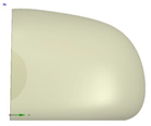 side view |
 |  rear view | ||
| Type B | 2.8 | 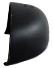 |  side view |
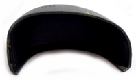 |  rear view |
| Material | Density (g/cm3) | Young’s Modulus (GPa) | Poisson Coefficient (–) | Tensile Strength (MPa) |
|---|---|---|---|---|
| Lexan [29] | 1.19 | 2.54 | 0.34 | – |
| AISI 1045 [30] | 7.85 | 200 | 0.30 | 560–850 |
| S235 [31] | 7.85 | 200 | 0.30 | 360–510 |
| S355 [32] | 7.85 | 210 | 0.30 | 510–680 |
| A36 [33] | 7.80 | 20.0 | 0.26 | 490–620 |
| Material | A Yield Stress (MPa) | B Hardening Constant (MPa) | n Hardening Exponent (–) | C Rate Constant (–) |
|---|---|---|---|---|
| Lexan [29] | 75.8 | 68.9 | 1 | 0 |
| AISI 1045 [30] | 553.0 | 600.0 | 0.234 | 0.0134 |
| S235 [31] | 480.0 | 153.0 | 0.360 | 0.0141 |
| S355 [32] | 448.0 | 782.0 | 0.562 | 0.0247 |
| A36 [33] | 286.1 | 500.1 | 0.228 | 0.0220 |
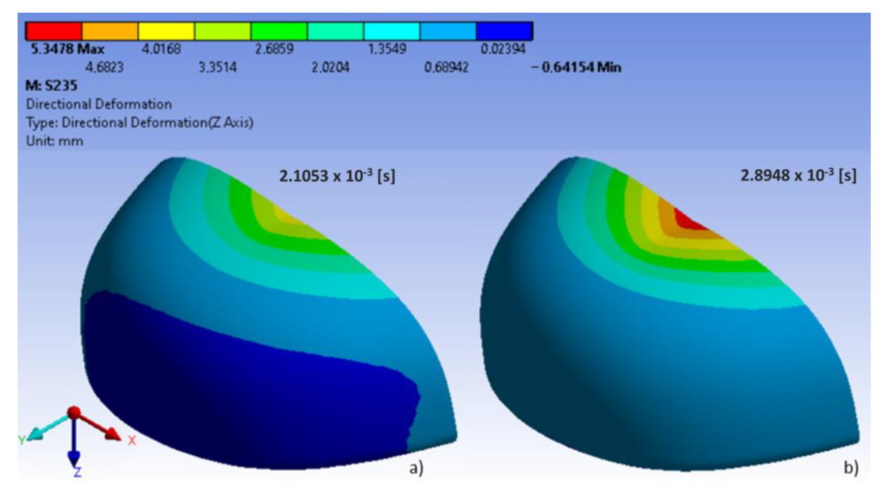
| Material | Deformation (Displacement in Z Direction) (mm) | H–vM Equivalent Stress (MPa) | Tensile Strength (MPa) |
|---|---|---|---|
| Lexan | 7.400 | 80.3 | Not applicable |
| AISI 1045 | 4.048 | 858.0 | 560–850 * |
| S235 | 5.340 | 494.0 | 360–510 * |
| S355 | 5.440 | 484.0 | 510–680 * |
| A36 | 6.520 | 311.0 | 490–620 * |
Disclaimer/Publisher’s Note: The statements, opinions and data contained in all publications are solely those of the individual author(s) and contributor(s) and not of MDPI and/or the editor(s). MDPI and/or the editor(s) disclaim responsibility for any injury to people or property resulting from any ideas, methods, instructions or products referred to in the content. |
© 2022 by the authors. Licensee MDPI, Basel, Switzerland. This article is an open access article distributed under the terms and conditions of the Creative Commons Attribution (CC BY) license (https://creativecommons.org/licenses/by/4.0/).
Share and Cite
Kropidłowska, P.; Irzmańska, E.; Gołębiowski, Ł.; Jurczyk-Kowalska, M.; Boczkowska, A. Analysis of the Impact Resistance of Toecaps by the Finite Element Method: Preliminary Studies. Int. J. Environ. Res. Public Health 2023, 20, 152. https://doi.org/10.3390/ijerph20010152
Kropidłowska P, Irzmańska E, Gołębiowski Ł, Jurczyk-Kowalska M, Boczkowska A. Analysis of the Impact Resistance of Toecaps by the Finite Element Method: Preliminary Studies. International Journal of Environmental Research and Public Health. 2023; 20(1):152. https://doi.org/10.3390/ijerph20010152
Chicago/Turabian StyleKropidłowska, Paulina, Emilia Irzmańska, Łukasz Gołębiowski, Magdalena Jurczyk-Kowalska, and Anna Boczkowska. 2023. "Analysis of the Impact Resistance of Toecaps by the Finite Element Method: Preliminary Studies" International Journal of Environmental Research and Public Health 20, no. 1: 152. https://doi.org/10.3390/ijerph20010152