

Design and Implementation of a Chain-Type Direct Push Drilling Rig for Contaminated Sites

 ,
, 
 , ,
, , 
Abstract
:1. Introduction
2. Principle of the Design
- i—operating transmission ratio,
- n1—input speed,
- n2—output speed,
- u—kinematic transmission ratio,
- z1—teeth number of driving sprocket,
- z2—teeth number of driven sprocket.
3. General of C-DP Drilling Rig
3.1. C-DP Drilling Rig Description
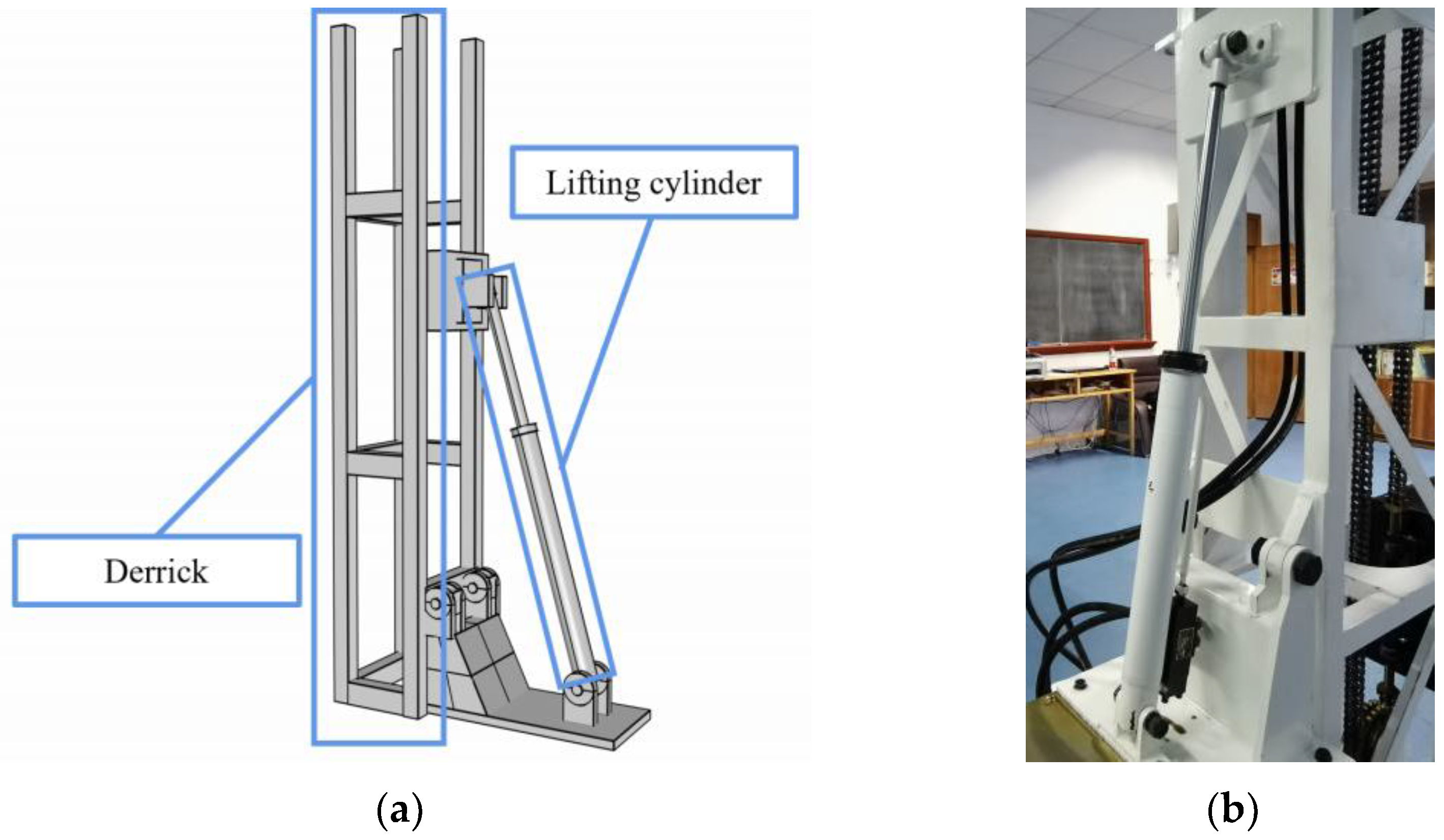
3.2. Direct Propulsion Module
3.3. Regulating Module
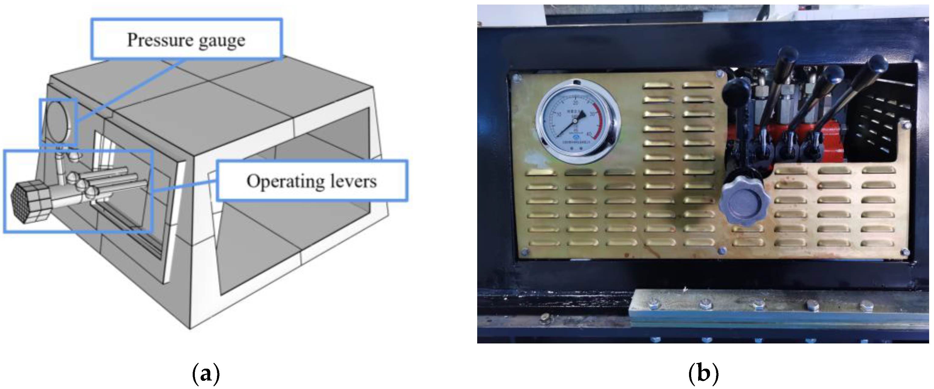
3.4. Operation—Control Module
3.5. Stratum—Auxiliary Module
3.6. Hydraulic System
4. Drilling Tests
4.1. Test Materials
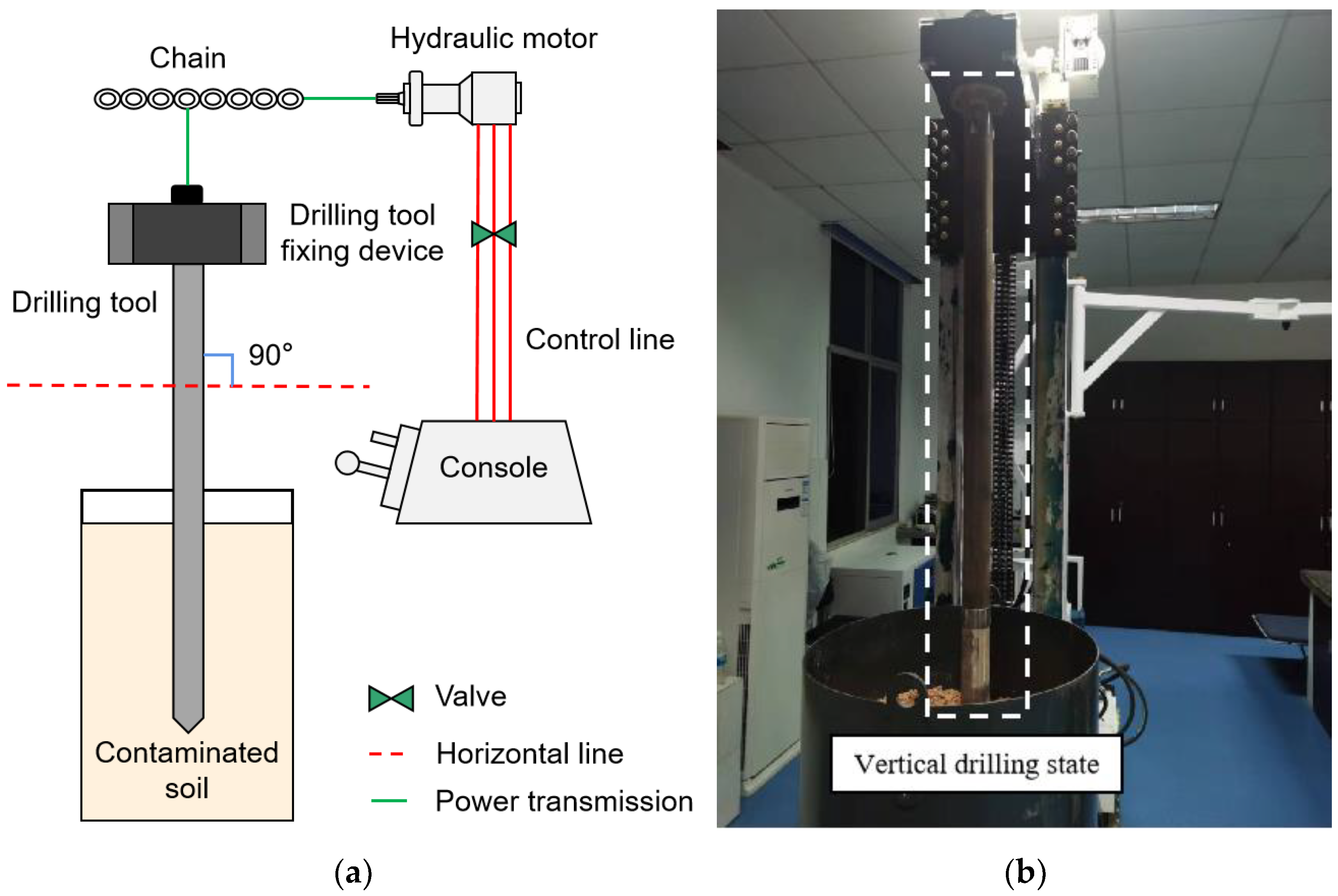
4.2. Test Procedure
5. Results and Discussion
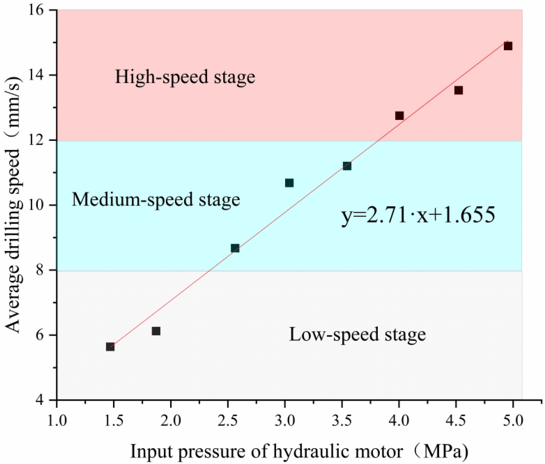
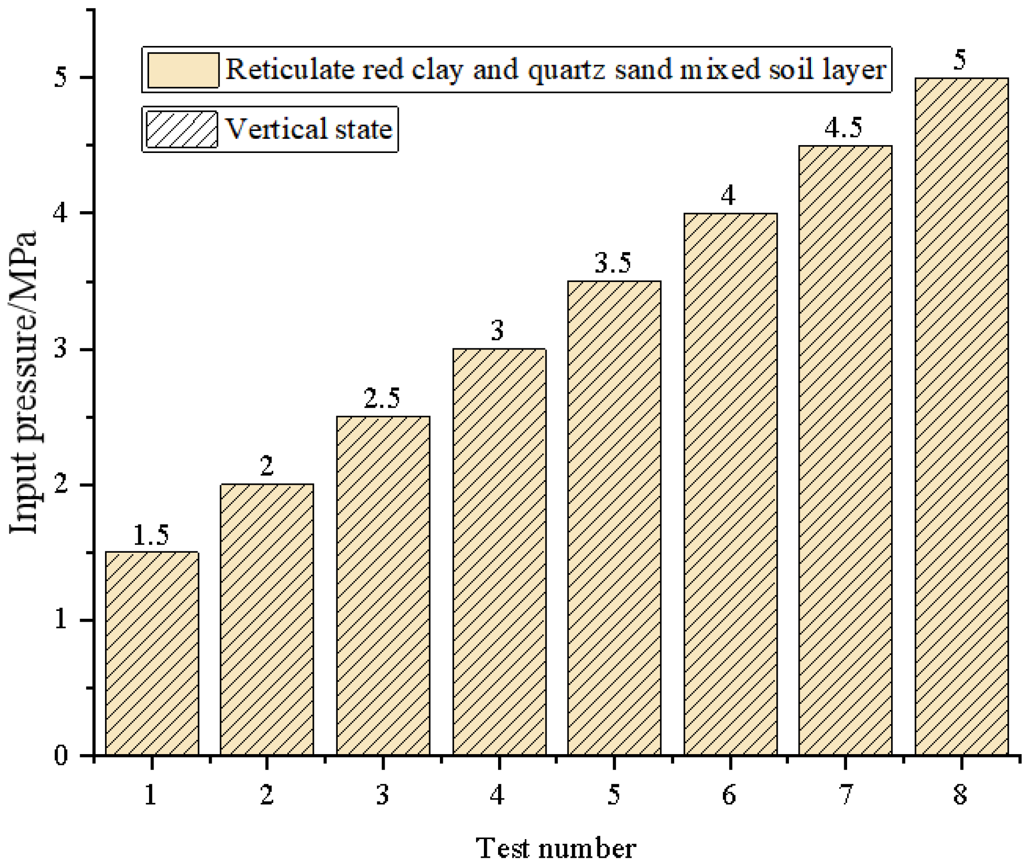
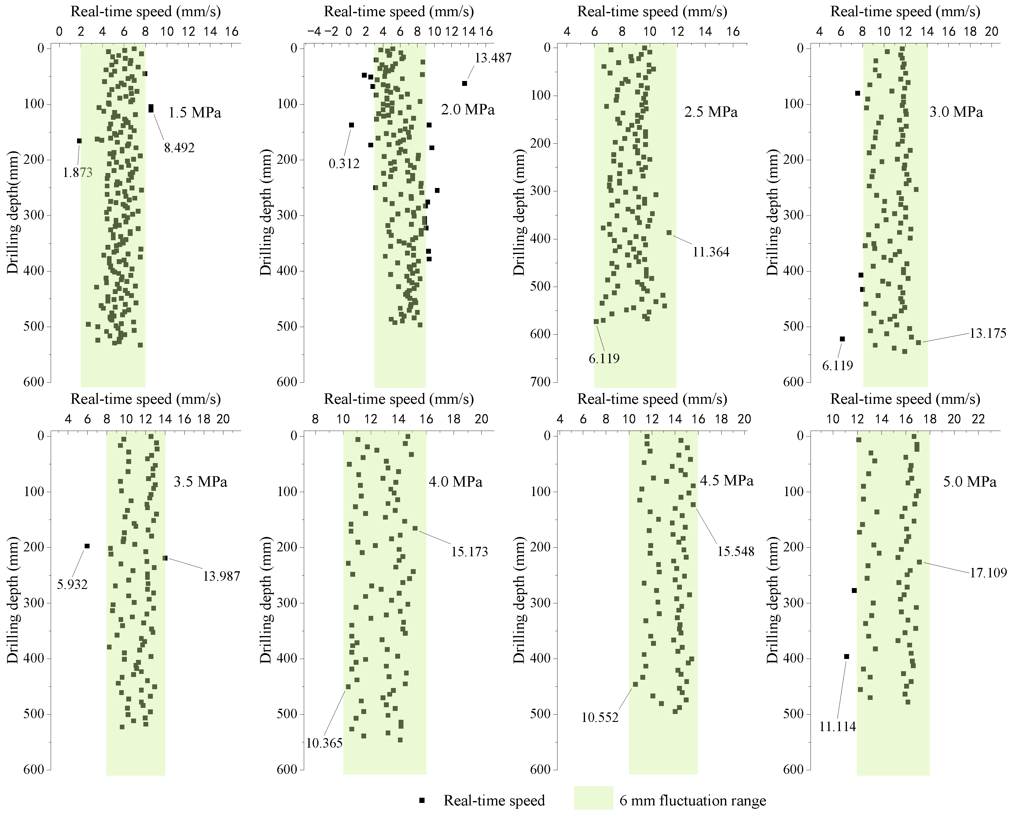
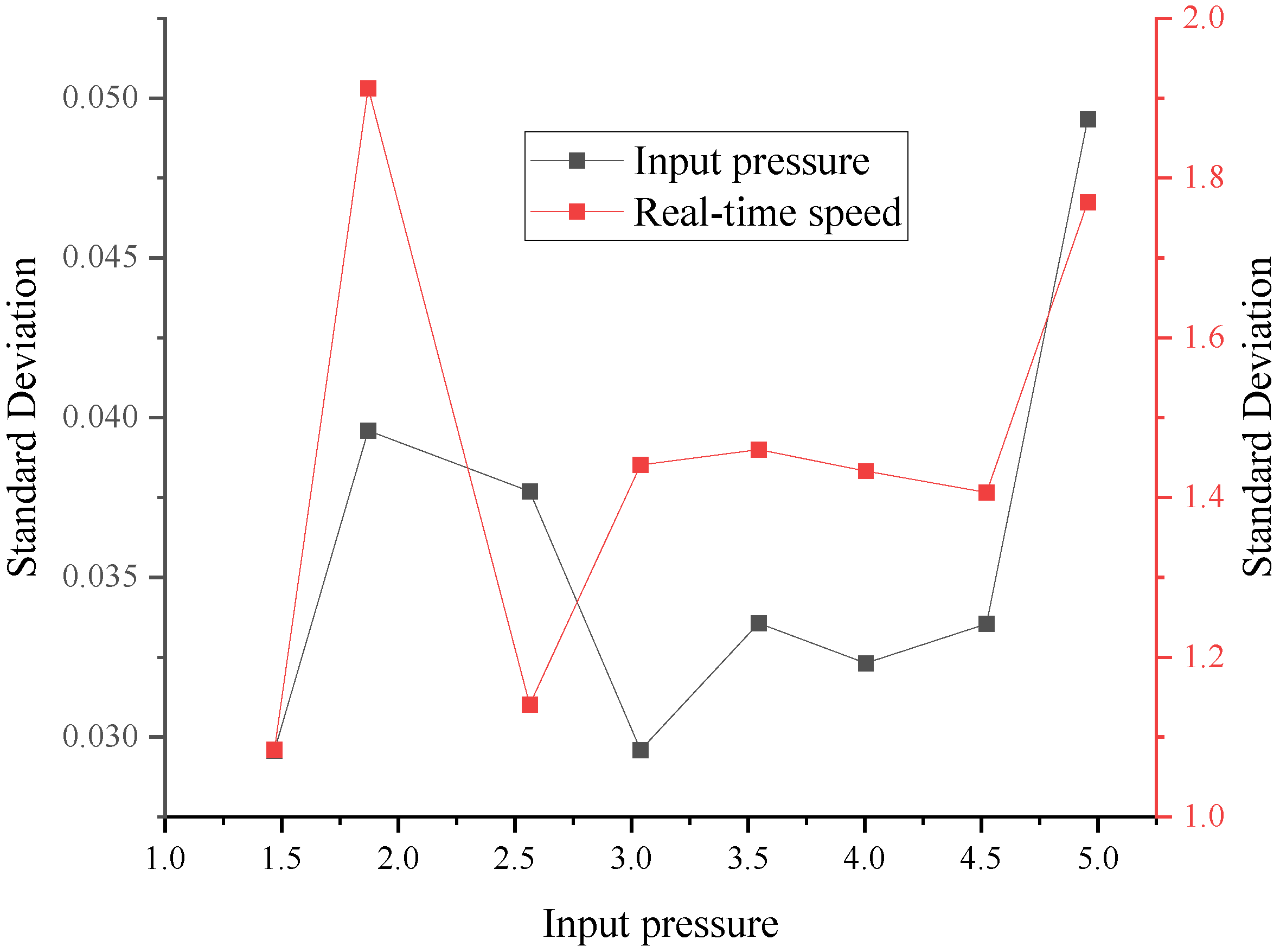
5.1. Parameters Calibration
- y—average drilling speed, mm/s.
- x—input pressure of hydraulic motor, MPa.
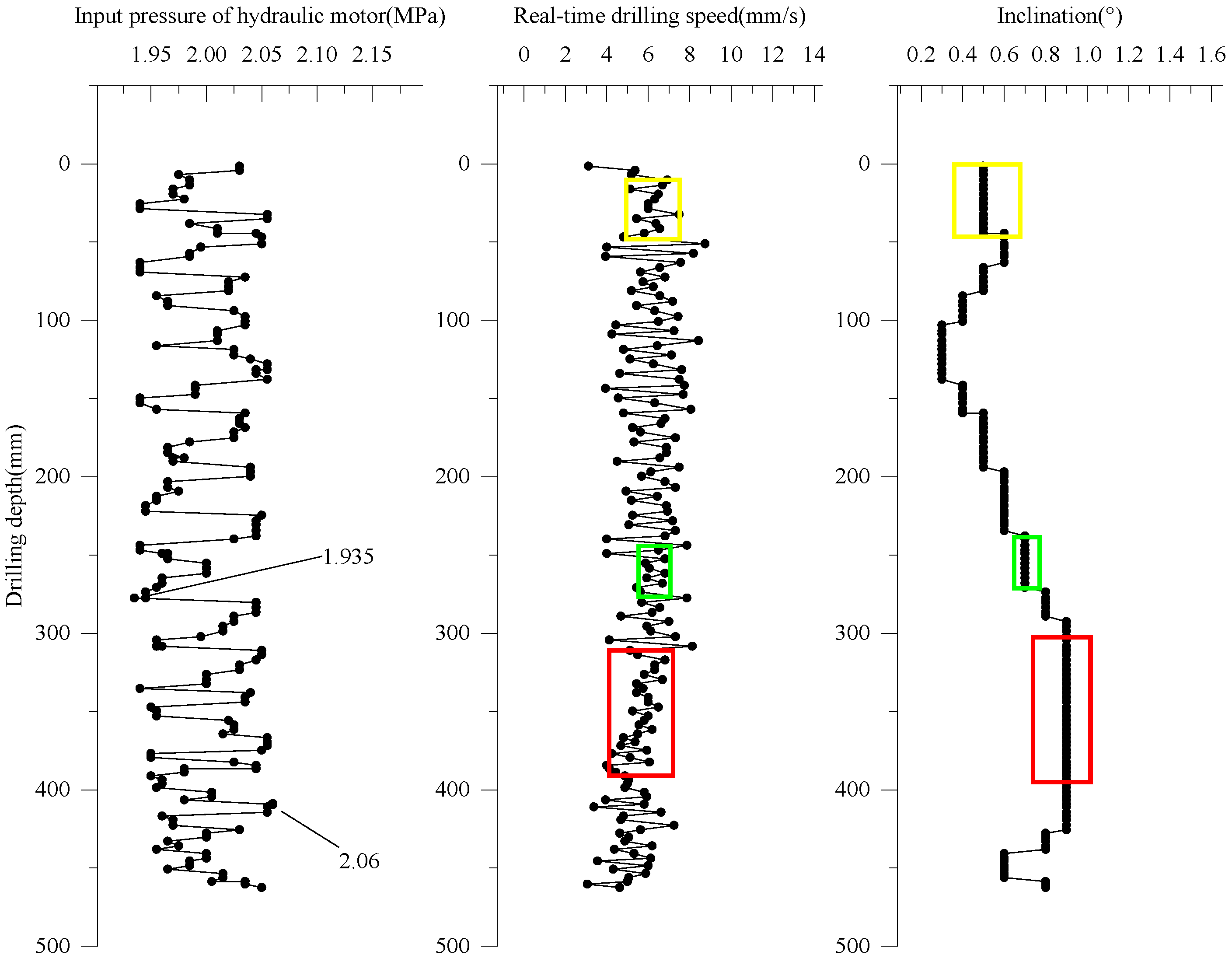
5.2. Simulated Soil Drilling Test
6. Conclusions
- (1)
- This paper proposed a new chain-type drilling structure design using a chain for drilling contaminated sites. The duplex chain design has a high transmission efficiency, decreases the space occupied, improves the drilling rig’s mobility, and allows for more various sites.
- (2)
- The modular theory was used to design drilling rigs, and the C-DP drilling rig can perform direct push drilling tests regarding drilling trajectory. The results show that the direct propulsion module and adjustment module can perform long-term continuous direct push drilling at a set angle. The stratum—auxiliary module can realize the simultaneous preparation of various contaminated soil layers and can be replaced with each other. The hydraulic system can provide power for different modules of the whole drilling rig.
- (3)
- A new C-DP drilling rig prototype was designed and built to validate our models while drilling in the indoor simulated soil layers.
- (4)
- The parameter calibration results show that the C-DP drilling rig can provide liquid pressure from 0 to 5 MPa. Moreover, the relationship between the drilling speed and input pressure is obtained. The simulated soil drilling test results show that the C-DP drilling rig can achieve accurate direct push drilling in a vertical state when the input pressure of the hydraulic motor is 2.000 MPa and the single pass is 462.461 mm. In addition, no large-angle deflection occurs under the condition of homogeneously soil layers.
Author Contributions
Funding
Institutional Review Board Statement
Informed Consent Statement
Data Availability Statement
Conflicts of Interest
References
- Krishna, A.K.; Mohan, K.R. Risk assessment of heavy metals and their source distribution in waters of a contaminated industrial site. Environ. Sci. Pollut. Res. 2014, 21, 3653–3669. [Google Scholar] [CrossRef] [PubMed]
- Brusseau, M.L.; Anderson, R.H.; Guo, B. PFAS concentrations in soils: Background levels versus contaminated sites. Sci. Total Environ. 2020, 740, 140017. [Google Scholar] [CrossRef] [PubMed]
- Balseiro-Romero, M.; Macías, F.; Monterroso, C. Characterization and fingerprinting of soil and groundwater contamination sources around a fuel distribution station in Galicia (NW Spain). Environ. Monit. Assess. 2016, 188, 292. [Google Scholar] [CrossRef] [PubMed]
- Mingkhwan, R.; Worakhunpiset, S. Heavy Metal Contamination Near Industrial Estate Areas in Phra Nakhon Si Ayutthaya Province, Thailand and Human Health Risk Assessment. Int. J. Environ. Res. Public Health 2018, 15, 1890. [Google Scholar] [CrossRef] [Green Version]
- Carriger, J.F.; Parker, R.A. Conceptual Bayesian networks for contaminated site ecological risk assessment and remediation support. J. Environ. Manag. 2021, 278, 111478. [Google Scholar] [CrossRef]
- Reddy, K.R. Technical Challenges to In-situ Remediation of Polluted Sites. Geotech. Geol. Eng. 2010, 28, 211–221. [Google Scholar] [CrossRef]
- Aggelopoulos, C.A.; Tsakiroglou, C.D. A new perspective towards in-situ cold plasma remediation of polluted sites: Direct generation of micro-discharges within contaminated medium. Chemosphere 2021, 266, 128969. [Google Scholar] [CrossRef]
- Sarker, A.; Nandi, R.; Kim, J.-E.; Islam, T. Remediation of chemical pesticides from contaminated sites through potential microorganisms and their functional enzymes: Prospects and challenges. Environ. Technol. Innov. 2021, 23, 101777. [Google Scholar] [CrossRef]
- Zivdar, Z.; Heidarzadeh, N.; Asadollahfardi, G. Remediation of diesel-contaminated soil by low-temperature thermal desorption. Int. J. Environ. Sci. Technol. 2019, 16, 6113–6124. [Google Scholar] [CrossRef]
- De Jesus, K.L.M.; Senoro, D.B.; Dela Cruz, J.C.; Chan, E.B. Neuro-Particle Swarm Optimization Based In-Situ Prediction Model for Heavy Metals Concentration in Groundwater and Surface Water. Toxics 2022, 10, 95. [Google Scholar] [CrossRef]
- Glatz Brubakk, K.; Gjengedal, E.L.F.; Enger, Ø.; Sripada, K. Ammunition Waste Pollution and Preliminary Assessment of Risks to Child Health from Toxic Metals at the Greek Refugee Camp Mavrovouni. Int. J. Environ. Res. Public Health 2022, 19, 10086. [Google Scholar] [CrossRef] [PubMed]
- Aithani, D.; Jyethi, D.S.; Yadav, A.K.; Siddiqui, Z.; Khillare, P.S. Source apportionment and risk assessment of trace element pollution in Yamuna river water in Delhi: A probability based approach. Urban Water J. 2022, 1–12. [Google Scholar] [CrossRef]
- Sun, P. Study on application status of direct push drilling technology in contaminated site in contaminated site investigation. Drill. Eng. 2021, 48, 95–102. [Google Scholar]
- Gu, Q.; Guo, G.; Zhou, Y.; Yan, Z.; Li, F. Classification, Application and Selection of Contaminated Site Remediation Technology: An Overview. Res. Environ. Sci. 2008, 21, 197–202. [Google Scholar]
- Meng, J.; Li, X.; Sun, S.; Jiang, L.; Liu, Y. Review of Development in Sampling Device and Process the Investigation in Contaminated Soils. Soil Eng. Found. 2022, 36, 424–426. [Google Scholar]
- Rein, A.; Popp, S.; Zacharias, S.; Leven, C.; Bittens, M.; Dietrich, P. Comparison of approaches for the characterization of contamination at rural megasites. Environ. Earth Sci. 2011, 63, 1239–1249. [Google Scholar] [CrossRef]
- Dehnert, J.; Leven, C.; Trabitzsch, R.; Weiss, H. Ermittlung hochauflösender Nitratkonzentrationsprofile im Grundwasser mithilfe von Direct-Push-Sondierungen. Grundwasser 2010, 15, 221–230. [Google Scholar] [CrossRef]
- Johnson, B.A.; Carpenter, P.J. Geophysical response of slackwater and sandy terrace deposits near Savanna, Northwestern Illinois. Environ. Earth Sci. 2013, 68, 955–964. [Google Scholar] [CrossRef]
- Qin, P.; Li, H.; Liu, C. Application of Geoprobe drilling rig in investigation of the urban soil and water environment. Explor. Eng. (Rock Soil Drill. Tunn.) 2020, 47, 1–8. [Google Scholar]
- ASTM D6169-98(2005); Standard Guide for Selection of Soil and Rock Sampling Devices Used with Drill Rigs for Environmental Investigation. American Society for Testing and Materials (ASTM) International: West Conshohocken, PA, USA, 2015.
- Zhan, L.; Gong, B.; Lin, W.; Chen, Y. Technical requirement and selection of drilling and sampling techniques for contaminated sites by chemistry and mining industry. J. Eng. Geol. 2016, 24, 642–648. [Google Scholar]
- Davidson, K.B.; Lake, C.B.; Sweet, B.; Spooner, I.S. Examining the ultraviolet optical screening tool as a viable means for delineating a contaminated organic sediment. Sci. Total Environ. 2021, 799, 149408. [Google Scholar] [CrossRef]
- Bronders, J.; Van Keer, I.; Touchant, K.; Vanermen, G.; Wilczek, D. Application of the membrane interphase probe (MIP): An evaluation. J. Soils Sediments 2009, 9, 74–82. [Google Scholar] [CrossRef]
- Griffin, T.W.; Watson, K.W. A comparison of field techniques for confirming dense nonaqueous phase liquids. Ground Water Monit. Remediat. 2002, 22, 48–59. [Google Scholar] [CrossRef]
- McAndrews, B.; Heinze, K.; DiGuiseppi, W. Defining TCE plume source areas using the Membrane Interface Probe (MIP). Soil Sediment Contam. 2003, 12, 799–813. [Google Scholar] [CrossRef]
- McCall, W.; Christy, T.M.; Pipp, D.; Terkelsen, M.; Christensen, A.; Weber, K.; Engelsen, P. Field Application of the Combined Membrane-Interface Probe and Hydraulic Profiling Tool (MiHpt). Ground Water Monit. Remediat. 2014, 34, 86–96. [Google Scholar] [CrossRef]
- Kukacka, J.; Bastiaens, L.; De Vos, J.; Andersen, B. MIP-IN: New device for combined detection of pollutants and injection of reagents. Waste Forum. 2015, pp. 232–241. Available online: http://www.wasteforum.cz/cisla/WF_4_2015.pdf#page=72 (accessed on 15 January 2023).
- Leen, B.; Pilgaard, S.O. Soil Treatment Device and Use Thereof for Treating Contaminated Soil and/or Groundwater Contained Therein. U.S. Patent 10,525,514, 7 January 2020. [Google Scholar]
- McCall, W.; Christy, T.; Goodrich, J. Application of the Optical Image Profiler (OIP) to Characterize the Grimm Oil Site, Kalona, IA. 2016. Available online: https://www.researchgate.net/publication/311261352_Application_of_the_Optical_Image_Profiler_OIP_to_Characterize_the_Grimm_Oil_Site_Kalona_IA (accessed on 15 January 2023).
- Kober, R.; Hornbruch, G.; Leven, C.; Tischer, L.; Grossmann, J.; Dietrich, P.; Weiss, H.; Dahmke, A. Evaluation of Combined Direct-Push Methods Used for Aquifer Model Generation. Ground Water 2009, 47, 536–546. [Google Scholar] [CrossRef] [PubMed]
- Mitsuhata, Y.; Ando, D.; Imasato, T.; Takagi, K. Characterization of organic-contaminated ground by a combination of electromagnetic mapping and direct-push in situ measurements. Near Surf. Geophys. 2014, 12, 613. [Google Scholar] [CrossRef]
- Rackov, M.; Kuzmanovic, S.; Knezevic, I.; Cavic, M.; Pencic, M.; Cavic, D.; Cofaru, N.F. Analysis of Possible Concept Solutions of Chain Drives. In Proceedings of the 9th International Conference on Manufacturing Science and Education (MSE)-Trends in New Industrial Revolution, Sibiu, Romania, 5–7 June 2019. [Google Scholar]
- Ghimisi, S.; Nicula, D. Actions to increase the reliability of the chain transmissions. In Proceedings of the 22nd International Conference on Innovative Manufacturing Engineering and Energy (IManE&E), Chisinau, Moldova, 31 May–2 June 2018. [Google Scholar]
- Velicu, R.; Papuc, R.; Gavrila, C.C.; Popa, S. Experimental study on guide friction contribution in global power loss of a tooth chain transmission. In Proceedings of the 13th International Conference on Tribology (ROTRIB), Galati, Romania, 22–24 September 2016. [Google Scholar]
- Hou, L.; Tang, R.; Xu, Y. Review of theory, key technologies and its application of modular product design. J. Mech. Eng. 2004, 40, 56–61. [Google Scholar] [CrossRef]
- Li, J.; Yang, Y. Creep behavior of unsaturated reticulate red clay under matric suction. KSCE J. Civ. Eng. 2018, 22, 582–587. [Google Scholar] [CrossRef]
- Zhang, C.; Li, J.-Z.; He, Y. Experimental Study on Viscoplastic Property of Unsaturated Reticulate Red Clay Used as an Engineered Barrier. Geofluids 2020, 2020, 1523659. [Google Scholar] [CrossRef]


| Performance | Parameter |
|---|---|
| Rated Power (kW) | 11 |
| Rated Voltage (V) | 380 |
| Rated Current (A) | 21.5 |
| Rated Speed (r/min) | 1460 |
| Rated Efficiency (%) | 91.4 |
| Rated Frequency (Hz) | 50 |
| Protection Class | IP55 |
| Insulation Class | Class F |
Disclaimer/Publisher’s Note: The statements, opinions and data contained in all publications are solely those of the individual author(s) and contributor(s) and not of MDPI and/or the editor(s). MDPI and/or the editor(s) disclaim responsibility for any injury to people or property resulting from any ideas, methods, instructions or products referred to in the content. |
© 2023 by the authors. Licensee MDPI, Basel, Switzerland. This article is an open access article distributed under the terms and conditions of the Creative Commons Attribution (CC BY) license (https://creativecommons.org/licenses/by/4.0/).
Share and Cite
Sun, P.; Zhou, S.; Cao, H.; Cai, G.; Zhang, S.; Gao, Q.; Cheng, G.; Liu, B.; Liu, G.; Zhang, X.; et al. Design and Implementation of a Chain-Type Direct Push Drilling Rig for Contaminated Sites. Int. J. Environ. Res. Public Health 2023, 20, 3757. https://doi.org/10.3390/ijerph20043757
Sun P, Zhou S, Cao H, Cai G, Zhang S, Gao Q, Cheng G, Liu B, Liu G, Zhang X, et al. Design and Implementation of a Chain-Type Direct Push Drilling Rig for Contaminated Sites. International Journal of Environmental Research and Public Health. 2023; 20(4):3757. https://doi.org/10.3390/ijerph20043757
Chicago/Turabian StyleSun, Pinghe, Shengwei Zhou, Han Cao, Guojun Cai, Shaohe Zhang, Qiang Gao, Gongbi Cheng, Biao Liu, Gongping Liu, Xinxin Zhang, and et al. 2023. "Design and Implementation of a Chain-Type Direct Push Drilling Rig for Contaminated Sites" International Journal of Environmental Research and Public Health 20, no. 4: 3757. https://doi.org/10.3390/ijerph20043757
APA StyleSun, P., Zhou, S., Cao, H., Cai, G., Zhang, S., Gao, Q., Cheng, G., Liu, B., Liu, G., Zhang, X., Liu, Y., Wu, D., Ding, Z., Zeng, L., Liao, G., Liu, L., Wang, X., Xiao, T., Jin, J., & Yang, H. (2023). Design and Implementation of a Chain-Type Direct Push Drilling Rig for Contaminated Sites. International Journal of Environmental Research and Public Health, 20(4), 3757. https://doi.org/10.3390/ijerph20043757