Abstract
This paper presents a proposed fuzzy energy management strategy developed for a battery−super capacitor electric vehicle. In addition to providing different driving modes, the proposed strategy delivers the suitable type and amount of power to the vehicle. Furthermore, the proposed strategy takes into account possible failures in vehicle power sources. The speed and torque of the HEV traction machine are simultaneously controlled using a genetic algorithm that provides simultaneous tuning via the use of newly proposed cost functions that give the designer the ability to tradeoff and prioritize between the design variables to be minimized. The simulation results show that the intelligent speed and torque control and the fuzzy power management strategy improved the vehicle’s performance in terms of ripple minimization. The real-time simulation is conducted using the RT LAB simulator, and the results obtained correspond to those obtained in the numerical simulation using MATLAB/Simulink.
1. Introduction
The road transportation industry depends on oil, an exhausting source of polluting energy. To reduce or eliminate this dependence, researchers have used electric motors to replace the conventional EV traction chain, which relies on an internal combustion engine. Several research axes were born out of the increasing importance given to electric vehicles, such as control of electric propulsion systems [1,2], energy management [3], vehicular communication systems [4], autonomous vehicles [5], vehicle chassis systems [6], traction motor control [7], power electronics [8,9], power train architecture [10], vehicle safety [11], fault tolerance [12], and grid connected electric vehicles [13], which are among the biggest trends nowadays in automotive engineering.
During the last decade, several bioinspired algorithms, such as the genetic algorithm [14], particle swarm optimization [15], ant colony optimization [16], and adaptive quantum-inspired evolutionary algorithm [17], have been used in several engineering disciplines. These algorithms are employed because of their ability to automatically find optimal and near-optimal solutions in contrast with classical methods, which are tedious and time-consuming. While an HEV is undergoing a driving cycle, its torque and speed must be precisely controlled. In this paper, the DTC technique was chosen because of its fast torque response, which is highly recommended in HEV applications. PMSM ensures HEV traction because of its high efficiency, high torque to mass ratio, and fast recovery time during transitions. PMSM flux and torque are measured using an estimator that optimizes hardware as it requires fewer sensors than the classical estimator. The classical DTC technique requires the designer to fix the bounds of two hysteresis controllers and to tune one PI controller. DTC-SVM needs three PI controllers to be adjusted. Both of the previously mentioned control techniques force the user to use classical tuning methods or trial and error. When a fuzzy logic controller is used with DTC, the designer must select appropriate membership functions and a good system. It is worth noting that classical methods are too approximate. The authors in [18] used a classical method for finding controller gains. However, in their design approach, they assumed only a linearized plant in series with a PI controller, neglecting many nonlinear components, such as inverter and hysteresis controllers. Usually, the gains obtained from this method are not consistent.
A battery−supercapacitor is a good power source combination for use in HEV. First, both sources are rechargeable, which is an important feature that allows for energy recovery. Secondly, these two energy storage sources have a complementary characteristic, which makes their combination reduce the drawbacks of each source. For example, the discharge time of supercapacitors is very small compared with the battery discharge time. Supercapacitors have a low power density, whereas batteries have a high energy density. Supercapacitors have higher charge and discharge cycles in contrast with batteries [19]. In [20,21], an electric vehicle powered using battery and fuel cell is studied. In these works, the HEV was simulated for only a few seconds. This short simulation period does not allow for rating the effectiveness of the power management strategy, because the power sources’ state of charge will not be affected in a short period. In [22], the performance and lifetime of a hybrid electric vehicle is studied. However, the vehicle in that work is controlled using field-oriented control, which is very sensitive to parameter variation. In [23], improvement of the energy management strategy of hybrid electric vehicle is studied. Even though advanced artificial intelligence techniques are used, important power peaks in the order of kilowatts are still noted. The authors in [24] discussed energy management and fault-tolerant strategies for a fuel cell−supercapacitor HEV. The energy management proposed in that work resulted in a relatively deep discharge of the supercapacitor. In [25], the authors resumed the HEV system to design a vehicle speed controller into a first order transfer function, neglecting the presence of nonlinear devices such as AC machines, inverters, and hysteresis controllers. In that work, the PMSM stator flux and torque were estimated to be very sensitive to DC components, resulting in very poor estimations at low speeds.
In this paper, the HEV powered using a battery and supercapacitor is controlled using DTC-based space vector modulation. The PMSM stator flux and torque are measured using a robust estimator that requires a minimum number of sensors. An approach is proposed that makes it possible to adapt the genetic algorithm to HEV. In addition to self-tuning HEV regulators, this approach allows the designer to tradeoff or prioritize between the variables via an adequate proposed cost function. The use of vehicle power sources is managed by a proposed fuzzy power management strategy, which is intended to reduce the power source switching and hence reduce the DC bus ripples associated with each switching. A fuzzy set of rules is designed to provide the HEV with the quantity and quality of power required for traction. The effectiveness of the proposed power management strategy is verified through an extended 660 s simulation period.
This paper is structured as follows: Section 2 deals with electric vehicle modeling and presents a detailed analysis of the different forces exerted on the vehicle as it undergoes a driving cycle. The direct torque control technique used to control the torque of the PMSM, ensuring vehicle traction, is detailed in Section 3. Section 4 points out how a genetic algorithm is adapted for use with the electric vehicle system. Furthermore, the different steps that precede the formulation of the cost function are explained. Section 5 highlights the proposed fuzzy power management strategy used in this paper to control the battery and supercapacitor power flow. Section 6 concludes this paper and confirms the effectiveness of the proposed intelligent direct torque control technique and fuzzy power management using numerical simulation and a RT LAB simulator.
2. Hybrid Electric Vehicle Dynamics
The motion of an EV is governed by Newton’s second law, given below:
where Fext is the sum of all of the external forces acting on the EV, m represents vehicle mass, and “a” is the EV acceleration.
Equation (1) can be rewritten as the difference between the EV traction force Ftraction and the net resistive force Fr, as it is shown in the equation below:
The net resistive force acting on the EV while it is undergoing a given driving cycle is given by the following equation:
where Faero is the aerodynamic force, Fg is the road slope force, Ftire is the friction force between the vehicle tires and ground surface, and Facc represents the acceleration force required to achieve maximum vehicle speed from rest.
The aerodynamic force to which the hybrid electric vehicle is subjected is given by Equation (4), as shown below [26]:
where ρ represents air density, A stands for EV front area, Cd represents the aerodynamic coefficient, Vwheel is the EV longitudinal speed, and Vwind is the wind speed.
The slope force due to road inclination is given by Equation (5), where g represents gravity acceleration and α represents the road inclination angle.
The friction force between the vehicle tires and the ground surface is given by Equation (6), which predicts the values of the rolling resistance force, with acceptable accuracy for speeds up to 128 km/h [27]:
Acceleration force is modeled by Equation (7), where ta is the EV time constant characteristic. The data of the HEV used in this work are shown in Table 1.

Table 1.
Environment parameters.
The parameters of the PMSM used for HEV traction are presented in Table 1. This machine is chosen because of its robustness and its high torque-to-mass ratio. Its stator flux components and developed electromagnetic torque are given by Equations (8) and (9), respectively.
3. DTC Algorithm
When the driver pushes the accelerator pedal, they give the motor a torque reference to follow. As DTC provides a fast and precise torque response, it was chosen from among other control techniques in order to control the EV in this work. DTC is a vector control technique that was developed by Takahashi and M. Depenbrock in the 1980s. In classic DTC, the stator flux in the αβ frame, stator flux magnitude, electromagnetic torque, and stator flux angle are estimated using Equations (10)–(13), respectively.
Vsα and Vsβ are calculated using Equation (14), as shown below:
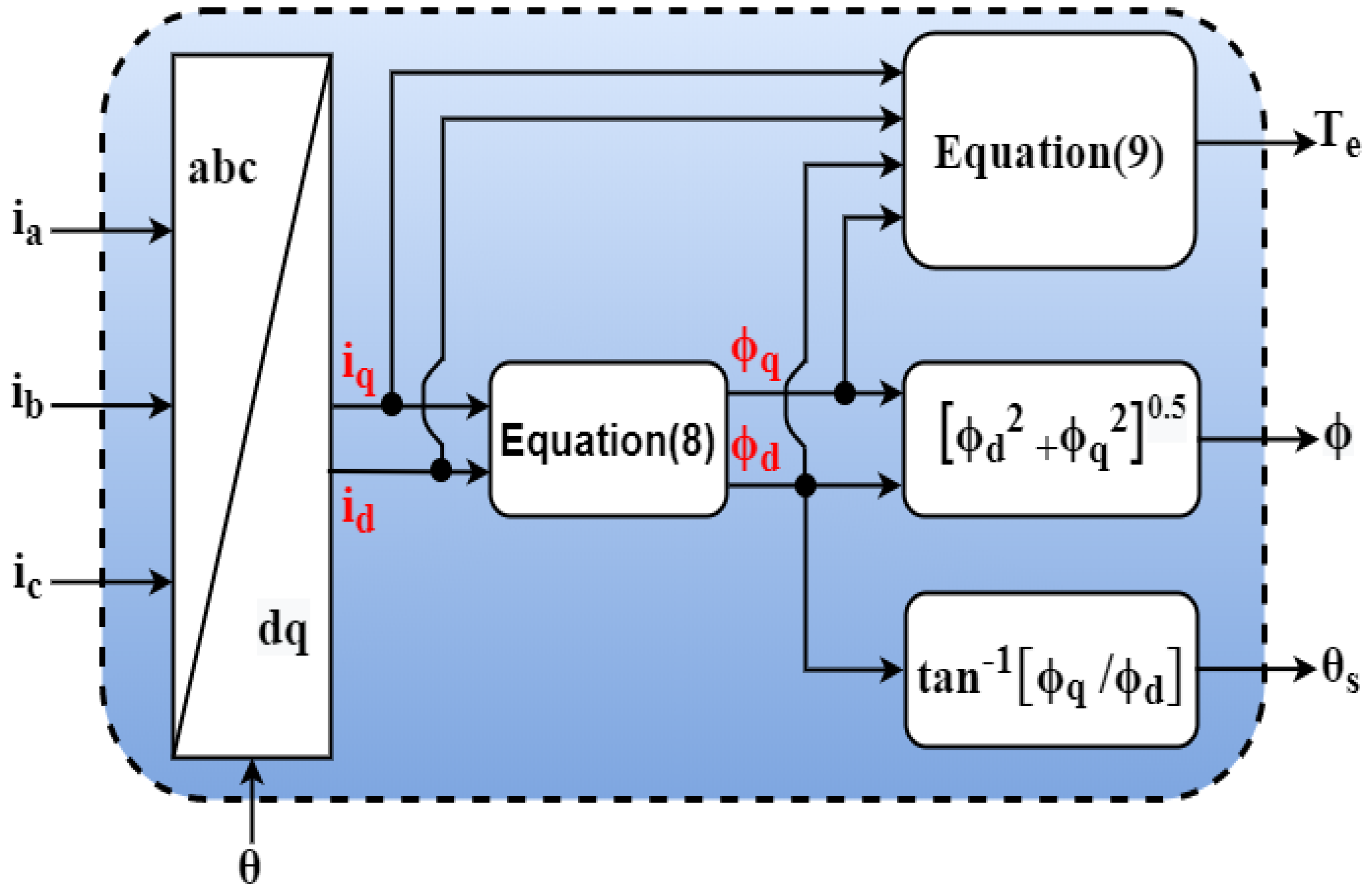
From the above equations, it can be seen that the estimator used in classical DTC requires three sensors for flux and torque measurements (ia and ib current sensors and VDC voltage sensor). In addition, the position sensor is needed to sense and control the EV speed. So, the total number of required sensors is equal to four. In this work, an estimator that requires less sensors and that does not involve any integral terms was used, and it is shown in the figure below (Figure 1).
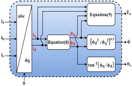
Figure 1.
Torque and flux estimator used.
To implement DTC with a speed loop, the torque and flux estimator shown above requires only three sensors, ia, ib, and θ (IC is deduced from ia, ib), whereas the classical estimator needs another extra sensor for the DC bus voltage measurement, as already stated in Equation (14).
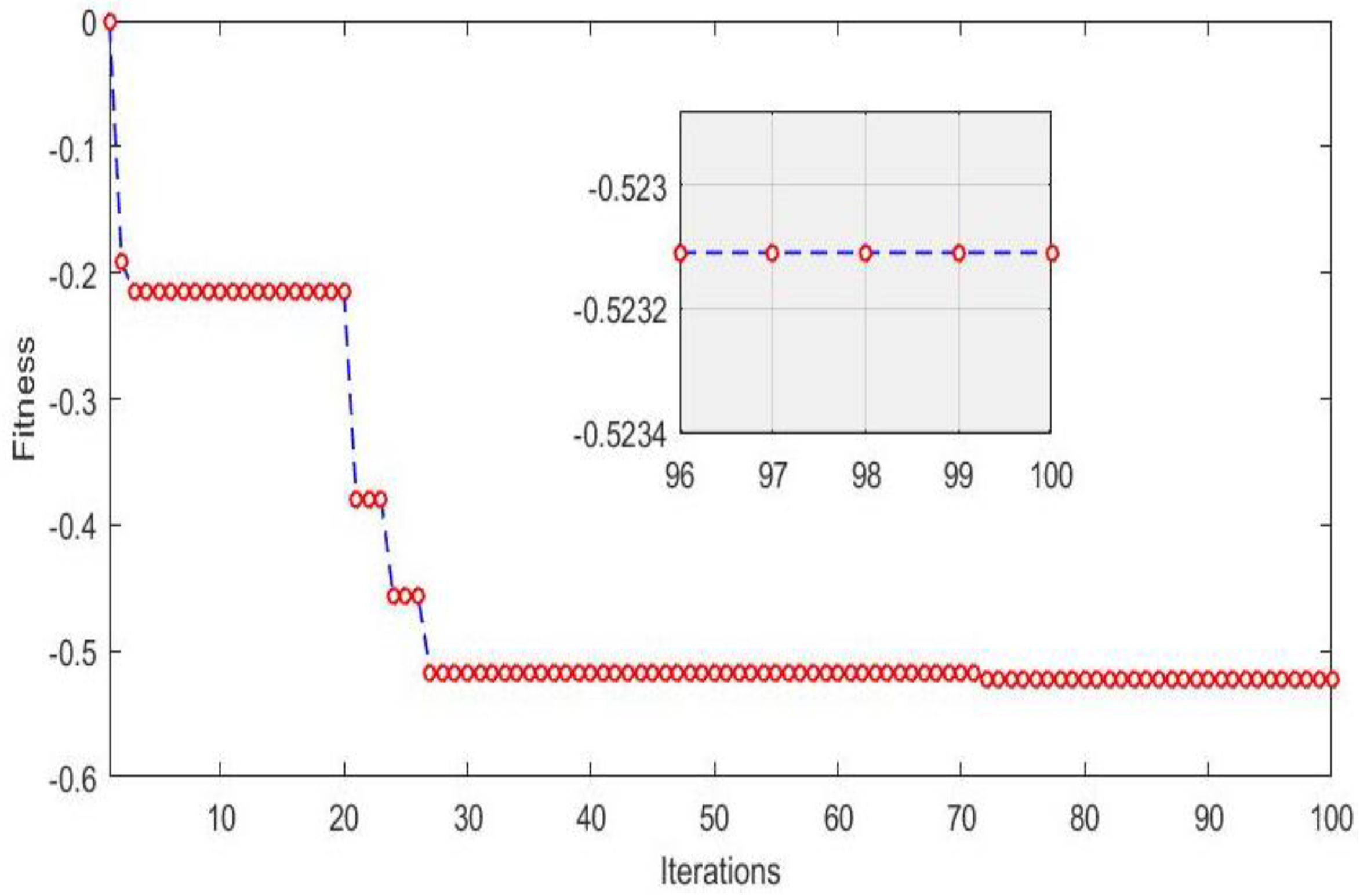
GA is a stochastic universal adaptive search optimization technique based on inherent selection [28,29,30,31]. In this algorithm, the chromosomes will mate through a process called crossover, producing offspring that combine their parent’s genes. In generation, few chromosomes will undergo mutation in their genes. The number of chromosomes that will undergo crossover and mutation is controlled via crossover and mutation rates. The basic steps of the GA algorithm are highlighted in Figure 2, and the GA parameters used are shown in Table 2.
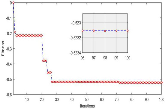
Figure 2.
Convergence of test function over iterations.
Table 2.
GA parameters used.
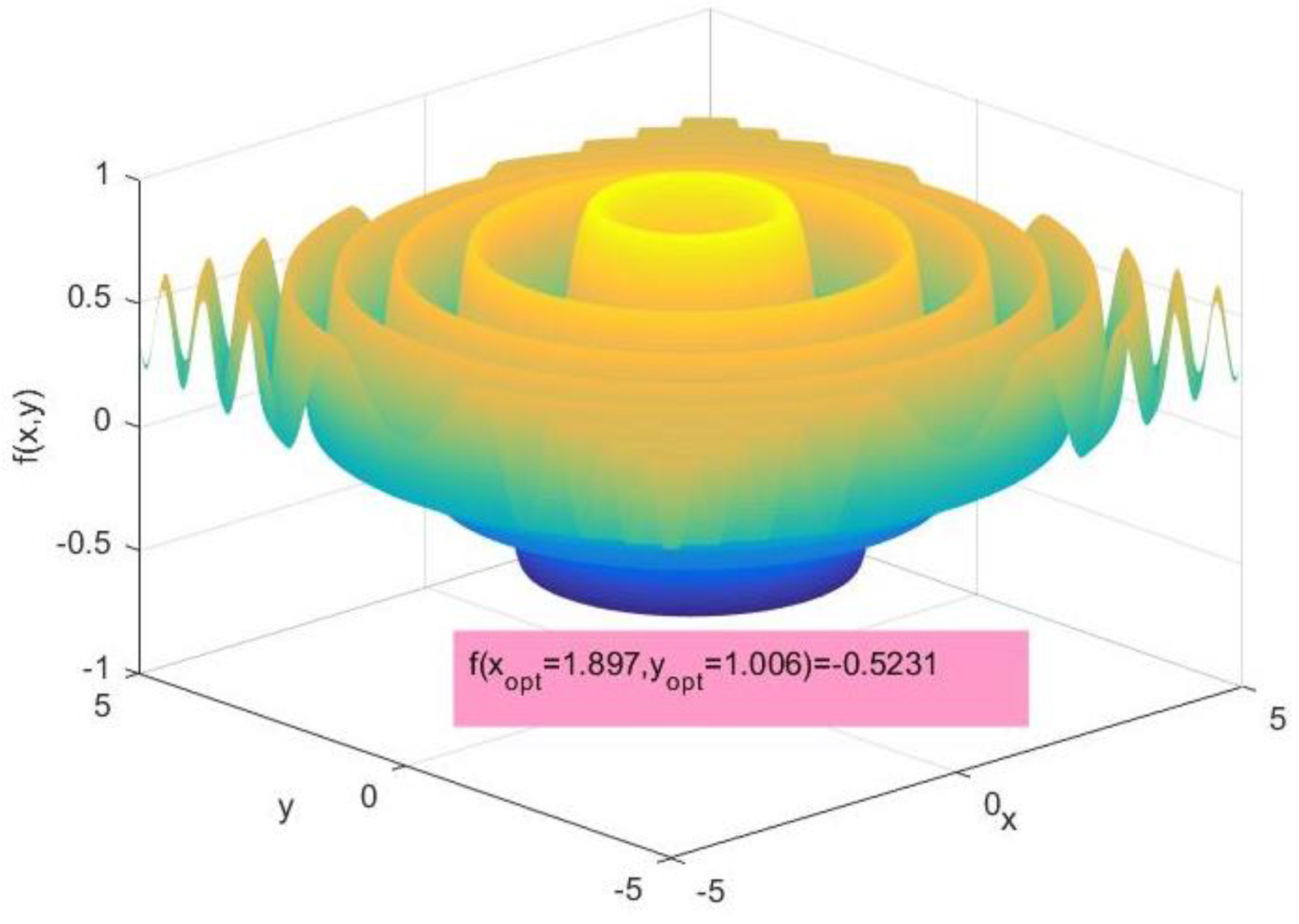
It is worth noting that the convergence of the GA algorithm used was tested using the benchmark test function [32,33,34,35] shown in Figure 3, whose expression is given by Equation (15). This benchmark function is full of local minima and has a unique global optimum, which may trap the algorithm if it is not well conceived. Figure 2 shows the result of minimizing Equation (15) using the GA algorithm. It can be seen that the GA algorithm succeeded in avoiding all of the local optimums and converged to the same global optimal solution already found antically.

Figure 3.
Benchmark test function used.
4. Cost Function and GA Adaptation
The global HEV scheme is shown in Figure 4. The outer controller PI1 is used for speed regulation and the two internal regulators, PI2 and PI3, are dedicated to torque and flux regulation. Two power sources—the battery and supercapacitor—feed the DC bus inverter through a bidirectional DC−DC converter. Information about the power sources used are highlighted in Table 3.
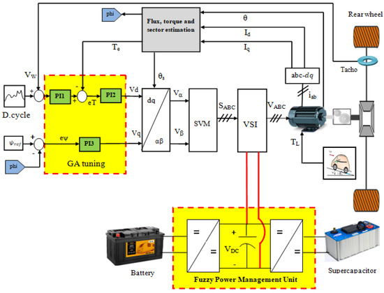
Figure 4.
Global HEV system.
Table 3.
Battery and supercapacitor parameters used.
The objective is to minimize the torque, speed, and flux ripples simultaneously. So, the best solution is the one that significantly minimizes all of the previously mentioned quantities. In any optimization algorithm, the cost function is responsible for selecting the population’s fittest particles. In this work, the cost function given by Equation (16) is used along with GA to simultaneously minimize the speed torque and flux errors.
α, β, and γ are weighting factors and their sum is equal to 1. These weighting factors represent the importance attributed to the different design variables. For example, torque ripples will be minimized more than speed and flux ripples if their corresponding weighting factor is greater than the other factors. The proposed cost function also allows the designer to tradeoff between design variables by putting α = β = γ. The average absolute speed error, average absolute torque error, and average absolute flux error are calculated using Equations (17)–(19), respectively:
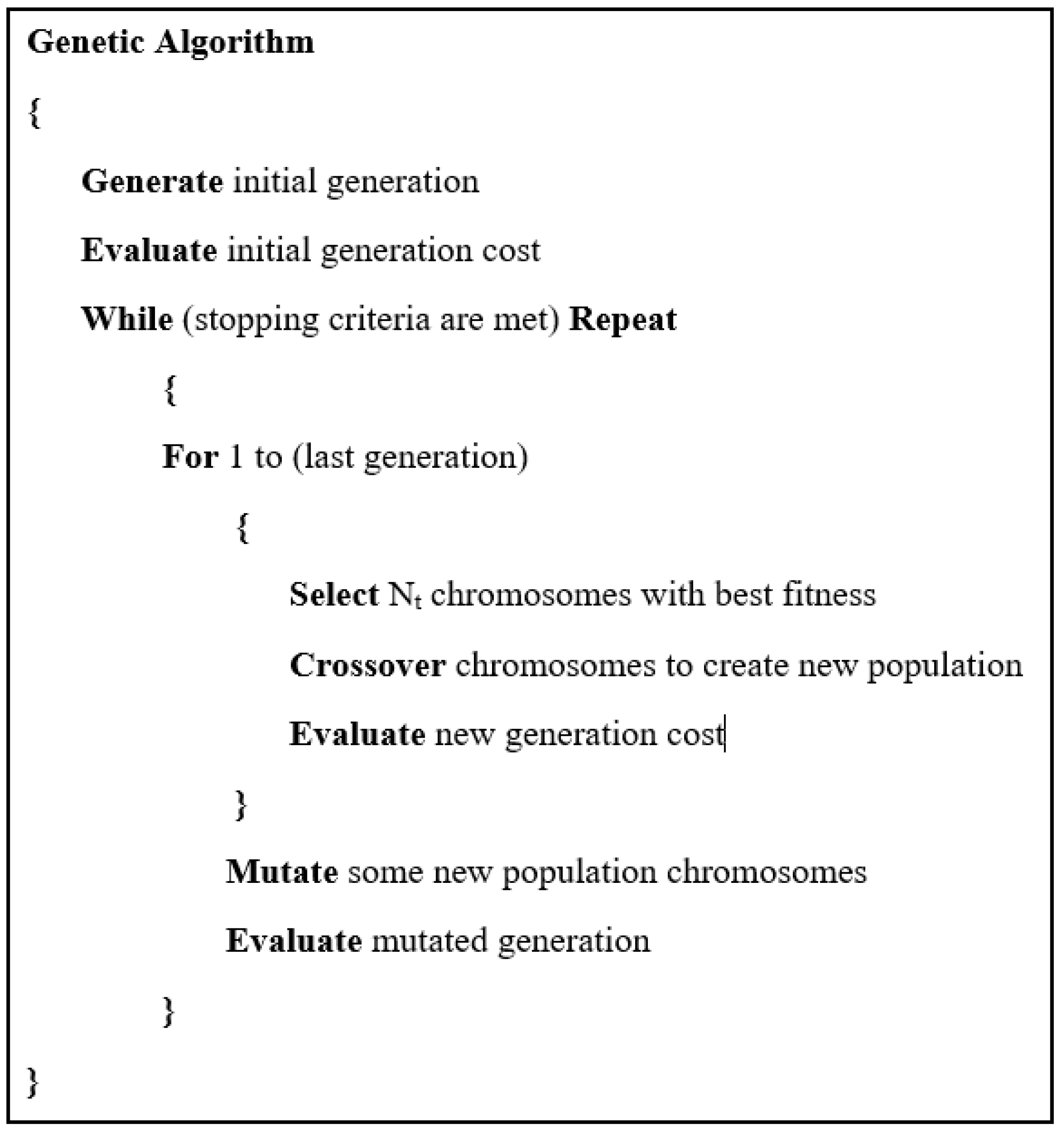
where Ωi and Ti represent the HEV reference speed and torque, respectively. and represent the measured HEV speed and torque, respectively. φref is the reference flux and it is equal to the permanent magnet flux, and φi is the measured PMSM flux at a given instant, n represents the length of speed, and torque absolute error vectors. Figure 5 depicts the genetic algorithm pseudo code used in this paper.

Figure 5.
Genetic algorithm pseudo code.
It is worth noting that while the HEV is running, the absolute error between its speed and the reference speed is calculated after each sampling time using Equation (17), as shown in Figure 6 (same applies for torque and flux errors).
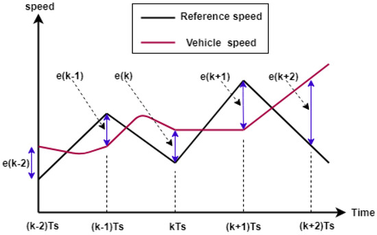
Figure 6.
Speed error extraction every sampling time.
5. Power Management
Figure 7 explains how the battery and the supercapacitor are connected to the inverter’s DC bus through two bidirectional DC−DC converters. Depending on the battery SOC, supercapacitor SOC, and the level of required load power, the fuzzy power management algorithm will deliver the supercapacitor a reference power .
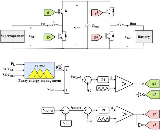
Figure 7.
Power sources and their corresponding control loops.
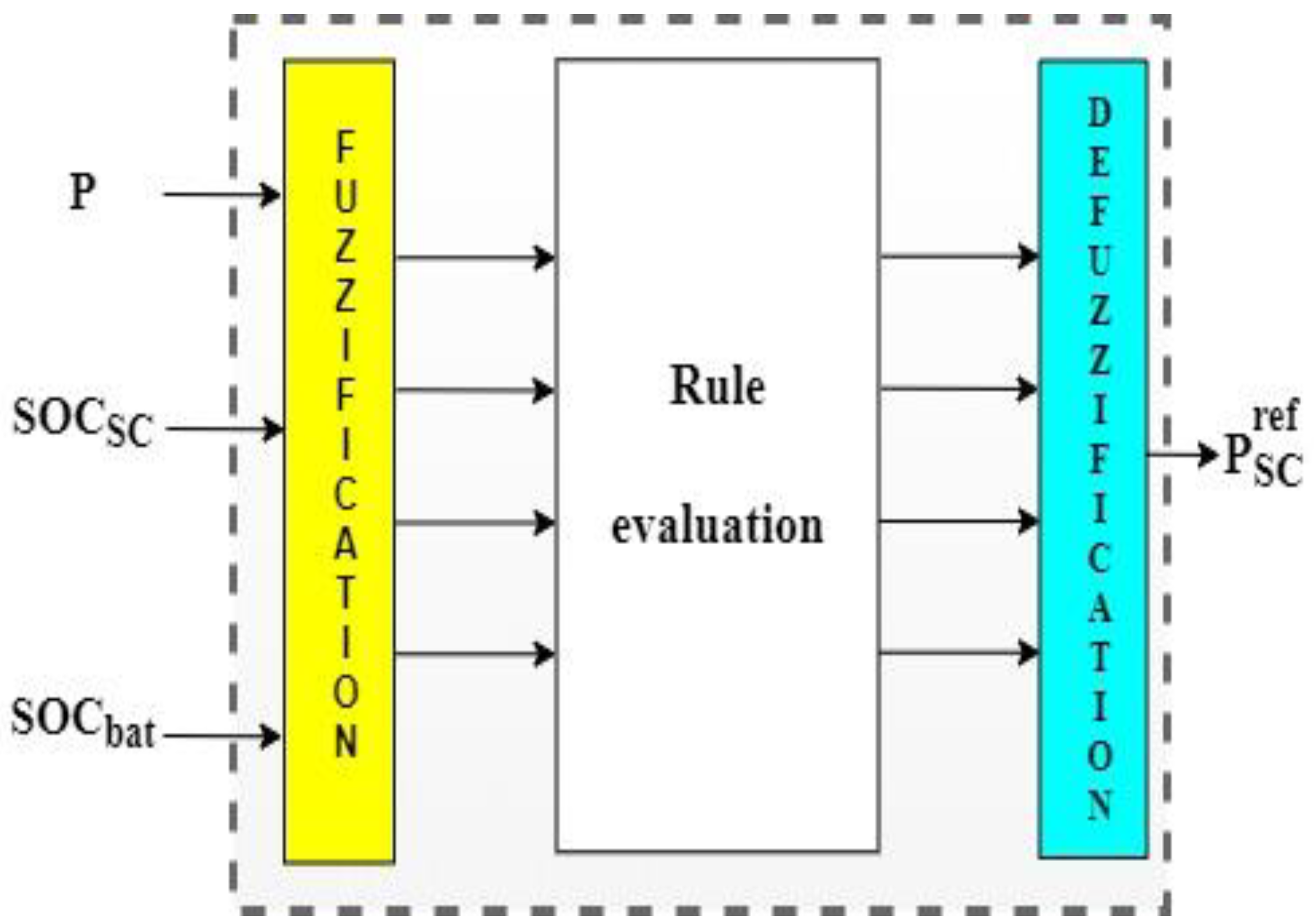
The internal structure of the fuzzy power management block shown in the figure above is detailed in Figure 8. This block fuzzifies its inputs using adequate membership functions, and then outputs the supercapacitor reference power based on a set of well-defined rules. It is worth noting that establishing rules governing the fuzzy logic controller’s operation is critical for good power management.
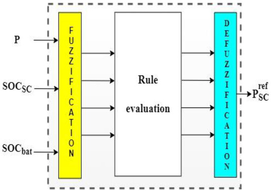
Figure 8.
Fuzzy power management unit.
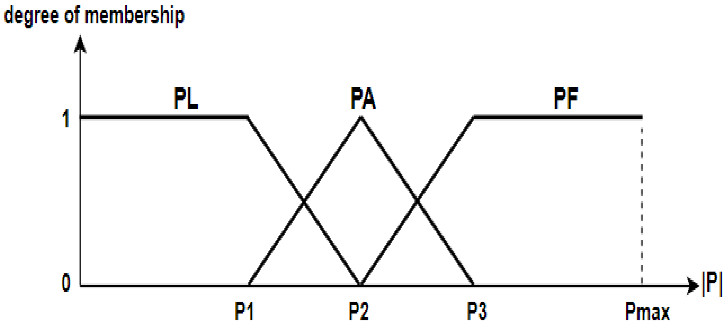
Figure 9 highlights the two trapezoidal and one triangular membership function used to fuzzify the required absolute HEV power. Three fuzzy sets are used—PL means low power, PA stands for average power, and PF signifies full power. The designer fixes the values of P1, P2, and P3, and they depend on the speed profile used.
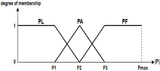
Figure 9.
Membership functions for absolute vehicle power.
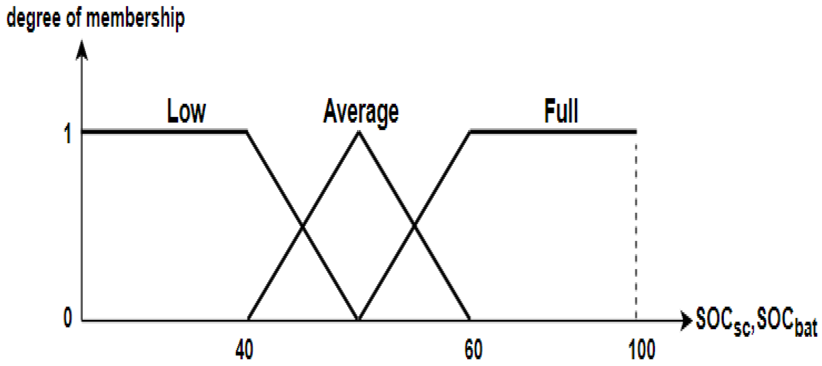
The membership function shown in Figure 10 is used to fuzzify the state of charge of the battery and supercapacitor. Two trapezoidal membership functions are used to fuzzify low and full states, and one triangular membership function fuzzifies the average battery and supercapacitor charging state.
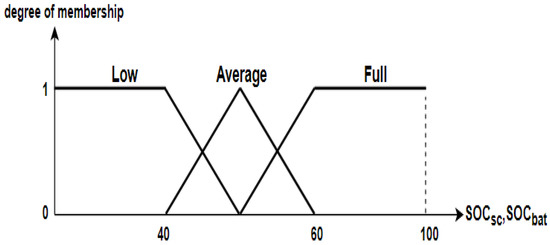
Figure 10.
Battery and supercapacitor SOC fuzzification.
The fuzzy logic controller represents the SC reference power. The membership shown in Figure 11 illustrates the output fuzzy sets used for deffuzification.
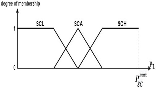
Figure 11.
Membership functions for the switch states.
6. Simulation and Results
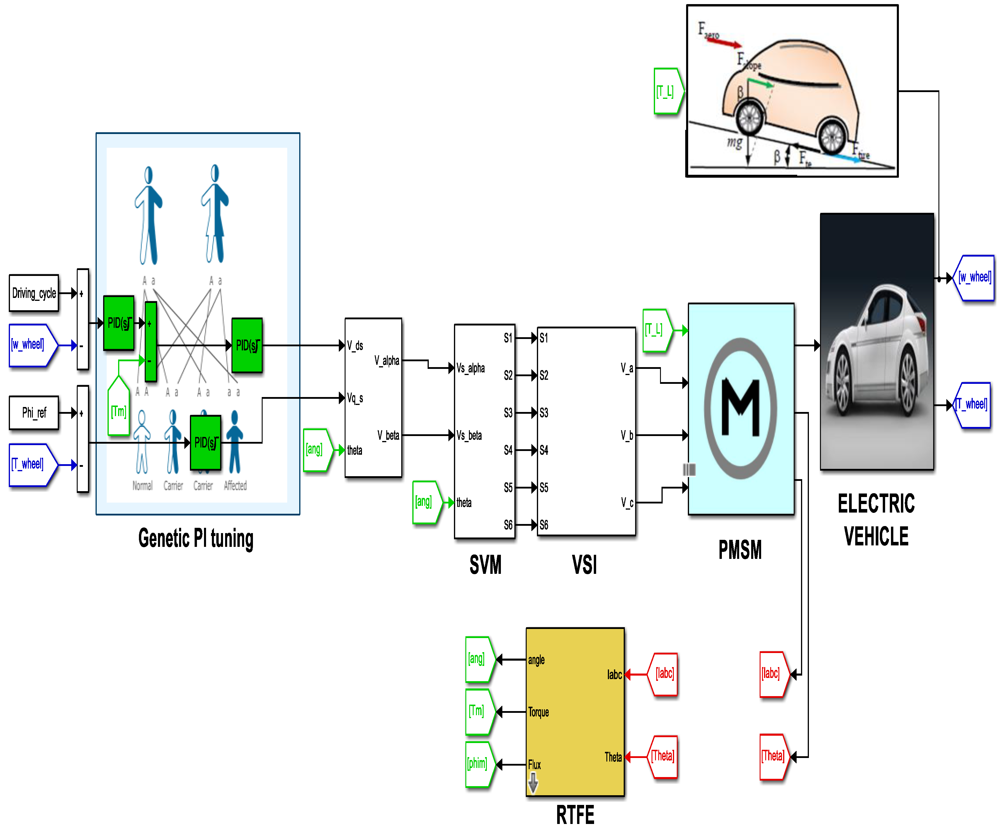
The global HEV simulation scheme built in the MATLAB/Simulink environment is shown in Figure 12. The outer controller is used for speed regulation and the two internal regulators are dedicated to torque and flux regulation. It can be seen that electric vehicle wheels are driven using PMSM, which is subjected to the different load torque already presented in Section 2.

Figure 12.
Overview of used HEV Simulation model.
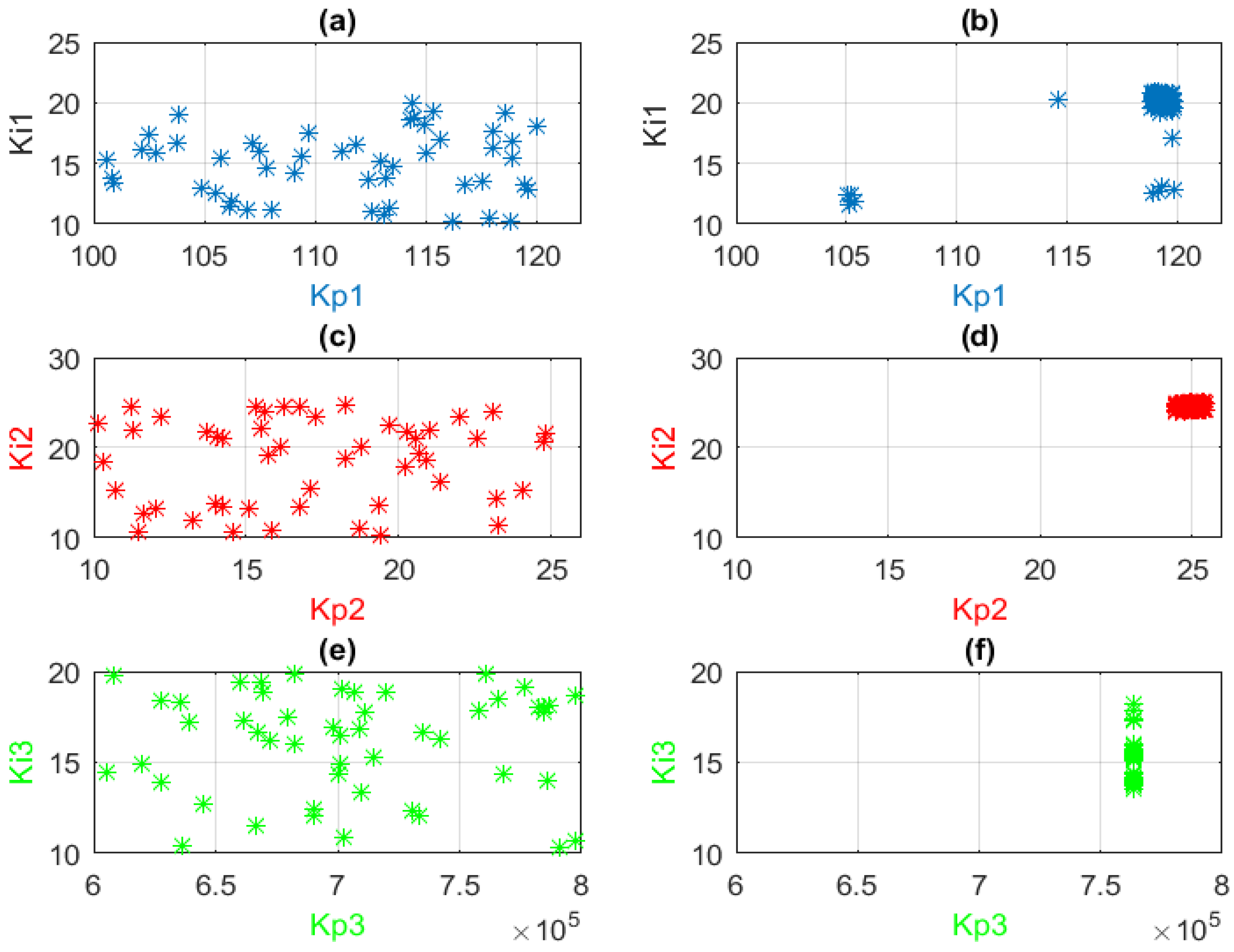
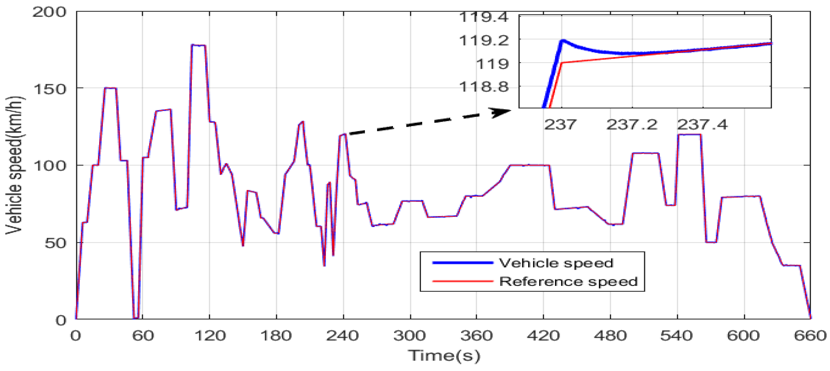
When GA is used for regulator tuning, a population of chromosomes will explore the search space in order to find the adequate PI combination that minimizes the cost function. Figure 13a,c,e shows the distribution of the first generation of potential solutions in the search space. It can be seen that the search space dimension of each controller is equal to two (two axes), and the coordinates of each potential solution in the search space represents a possible PI combination, which may result in the minimization of the cost function, given by Equation (16). Figure 13b,d,f shows that the last generation of chromosomes generated by GA for each PI controller has converged to an almost unique location, which represents the optimum PI gains. From these three last-mentioned figures, one can state that the selected optimum (Kp, Ki) combinations for PI1, PI2, and PI3 are (119.2, 20.3), (25.03, 24.97), and (7.64 × 10⁵, 15.77), respectively. The speed of the HEV is presented in Figure 14. One can notice that HEV speed precisely follows its reference, which contains slow, medium, and aggressive acceleration and decelerations.
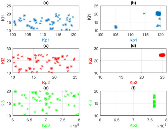
Figure 13.
Candidate solutions in the search space (a) PI1 at first iteration (b) PI1 at last iteration (c) PI2 at first iteration (d) PI2 at last iteration (e) PI3 at first iteration (f) PI3 at last iteration.
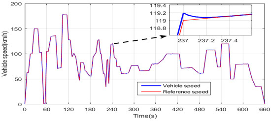
Figure 14.
HEV speed response using the GA DTC algorithm.
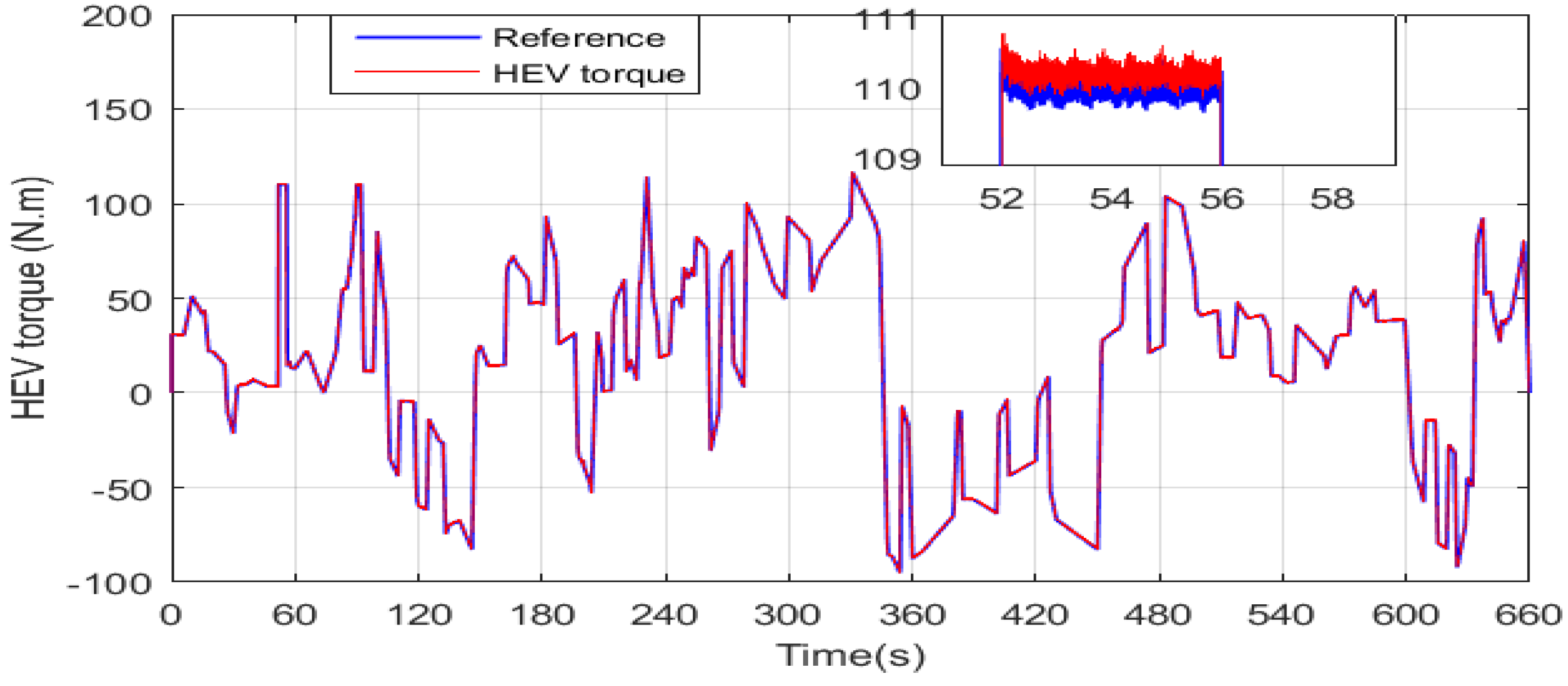
The electromagnetic torque developed by the HEV traction machine is shown in Figure 15. It can be seen that the PMSM torque response is fast and approximately matches the reference torque. From this figure, it can be seen that the traction machine operates in both the motor and generator mode, as the torque has positive and negative values.

Figure 15.
HEV torque response using the GA DTC algorithm.
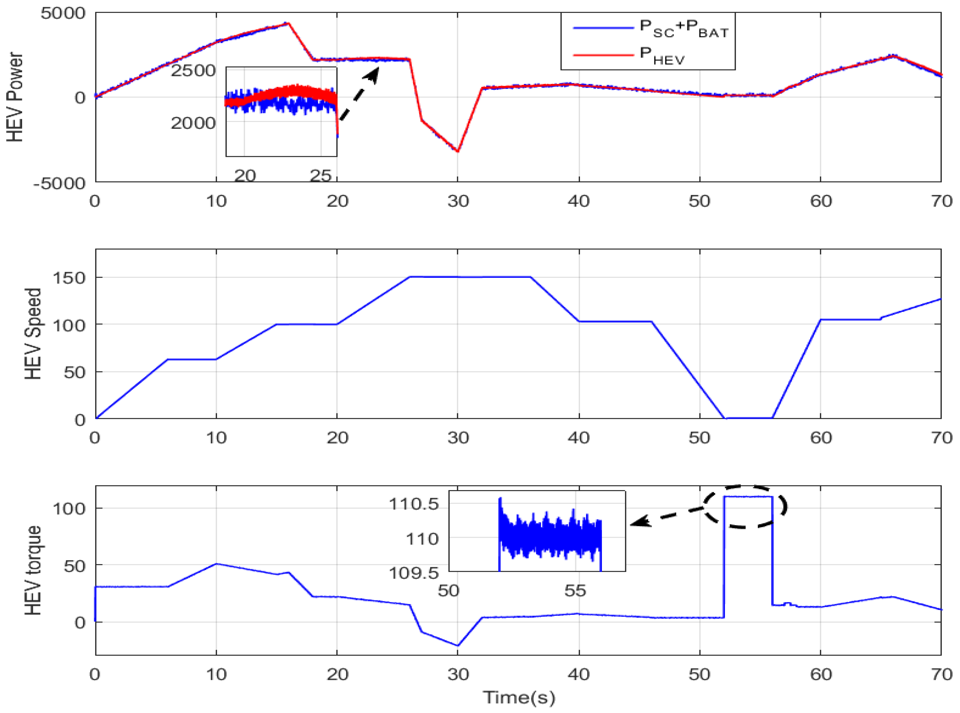
A magnification of the HEV power, speed, and torque during the period [0; 70 s] is provided in Figure 16. It can be seen that the DTC-SVM-based GA resulted in a narrow PMSM torque hysteresis band of 1 N·m, which represents almost one-tenth of the hysteresis band obtained with a two-level inverter in [22]. It can be seen that the battery and the supercapacitor-generated power is equal to the power developed by the PMSM for traction. Note that the power sources and motor ripples are very narrow compared with [22,23].
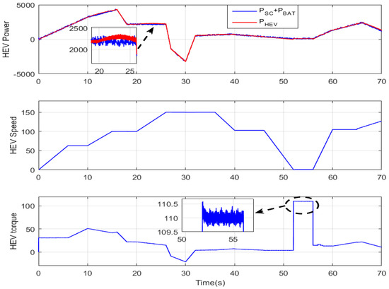
Figure 16.
Magnification of the HEV power, speed, and torque.
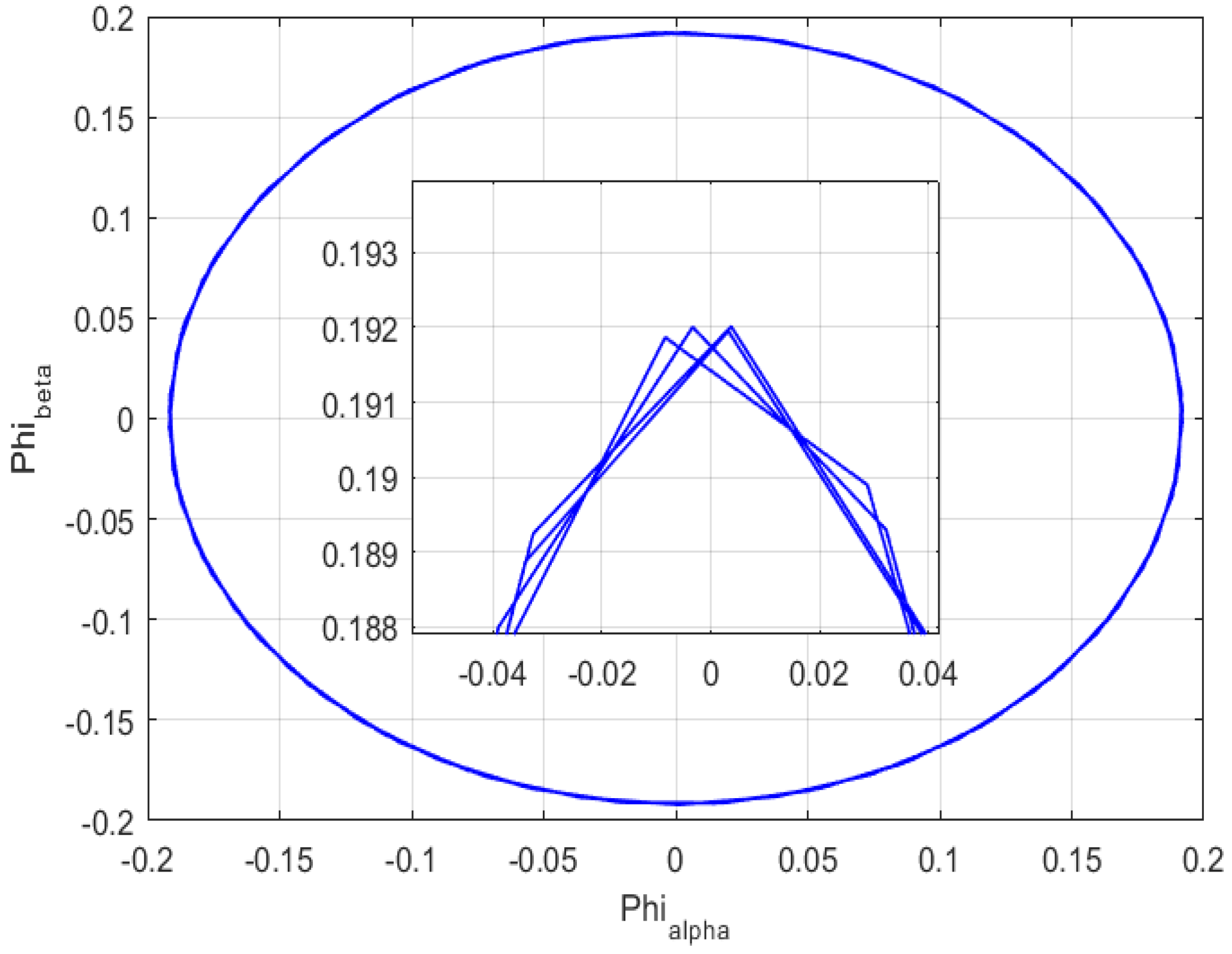
Figure 17 shows the PMSM stator flux on the alpha-beta frame. The circular shape means that the flux is constant in the time domain and its amplitude is equal to the circle radius, which is equal to the reference flux. The magnification in Figure 17 confirms that the PMSM flux follows its reference, which is equal to 0.192 Wb.
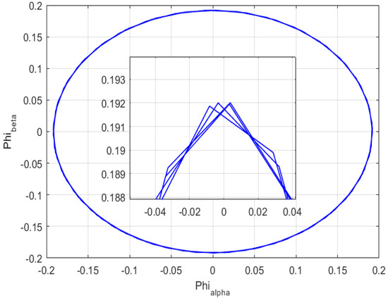
Figure 17.
PMSM stator flux using the GA DTC algorithm.
Figure 18 shows that the inverter DC bus voltage follows its reference value, which is equal to 560 V. The magnified area on the same figure shows that the ripples band is less than or equal to 10 V, and this is twice as small as what was obtained in [20]. This is because the established fuzzy rules suppressed many of the power source switchings.
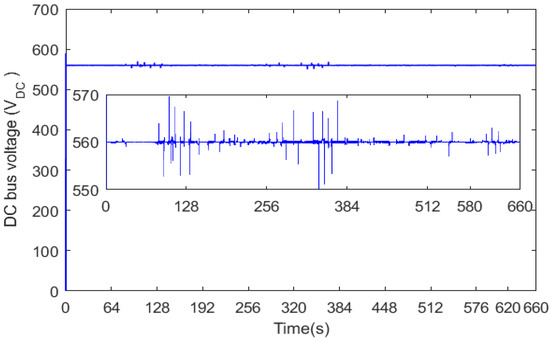
Figure 18.
Inverter DC bus voltage.
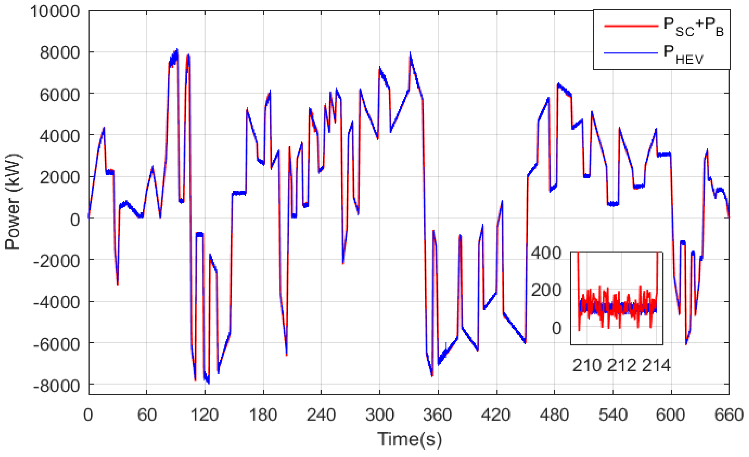
Figure 19 confirms the efficiency of the power management strategy. One can see that the power provided by the battery and/or supercapacitor is equal to the power developed by the HEV at every simulation instant. Furthermore, the magnified area on the same figure shows that the power has a very tolerable hysteresis band of almost 200 W.
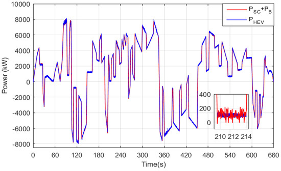
Figure 19.
Power sources and power developed by the vehicle.
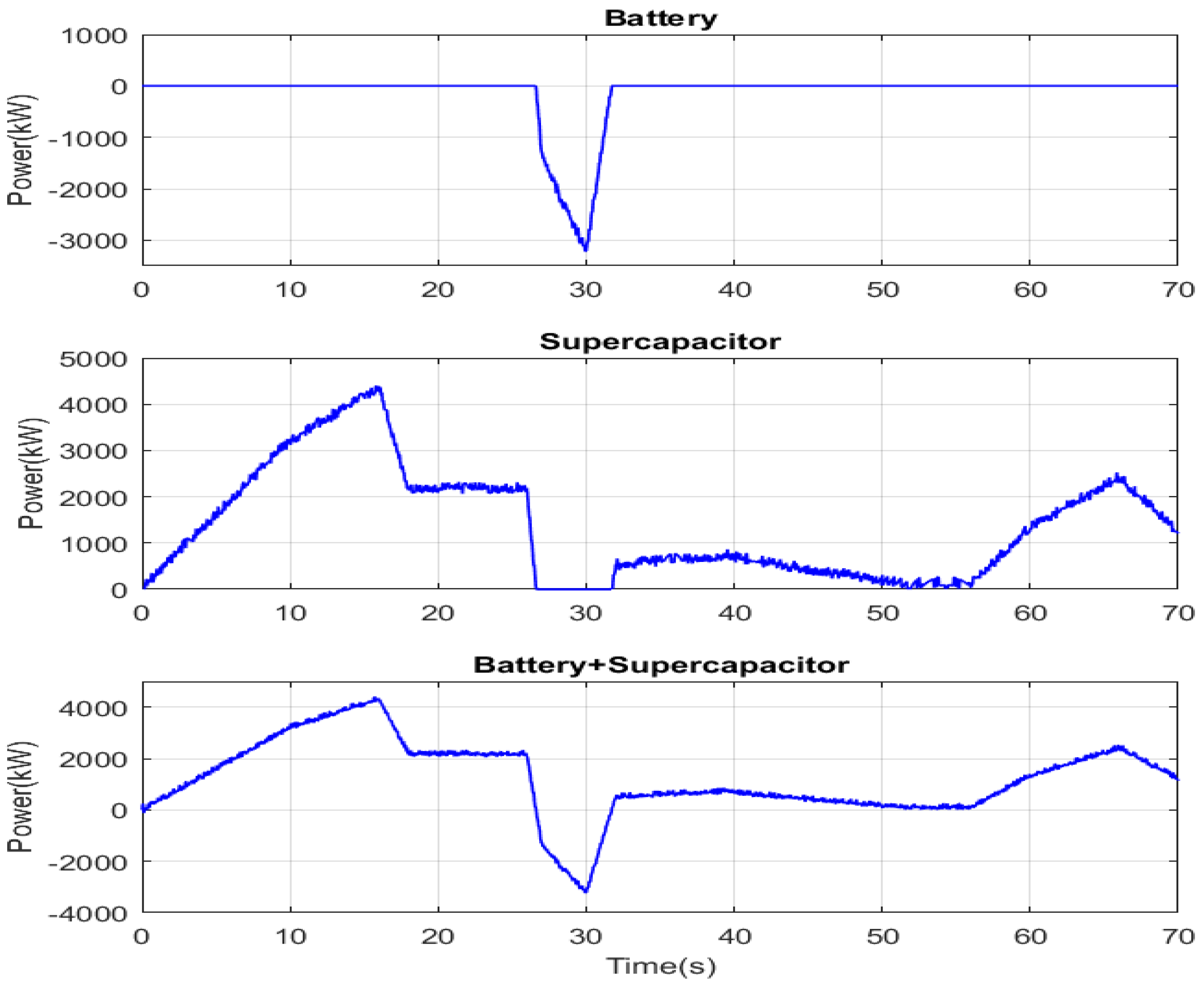
Figure 20 shows the battery and the supercapacitor power. At each instant, one can notice that their sum is equal to the reference HEV required power shown in the figure below. In addition, this figure clearly shows the different HEV operation modes, namely: the traction mode using the battery only, the traction mode using the supercapacitor only, the traction using both sources, supercapacitor charging, battery charging, and the charging of both power sources.
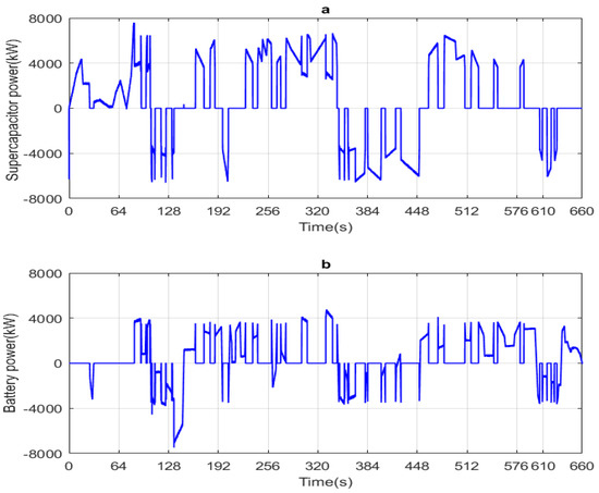
Figure 20.
Developed power and its reference (a) supercapacitor power (b) Battery power.
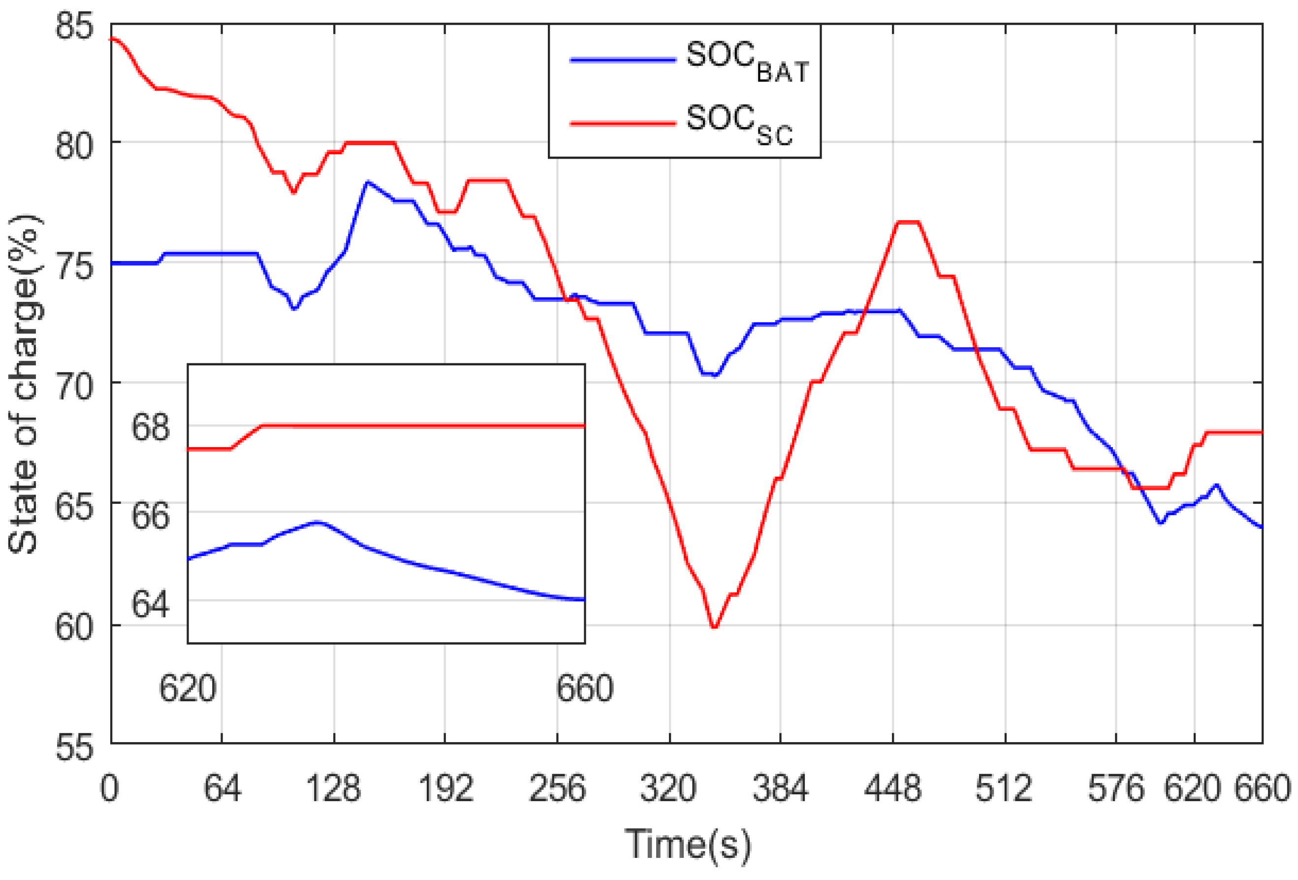
Figure 21 shows a magnification of the battery and supercapacitor powers along with their sum during the instant [0; 70 s]. It can be seen that their sum at each instant is equal to the HEV power produced by the traction motor. Furthermore, note that the supercapacitor ensures only HEV traction throughout the magnification period. The HEV is in a regenerative braking mode during the period [26.55; 31.75 s]. The restored power will be used to charge the battery, because its state of charge (SOC) is lower than that of the supercapacitor, as shown in Figure 22. From the previous figure, it can be seen that even though the SOC of the two power sources is initially different, their final SOC is nearly the same, which reflects good power management. From the figure, it can also be seen that the supercapacitor and/or battery are charging during the regenerative braking periods.

Figure 21.
Power developed by the sources and its reference.
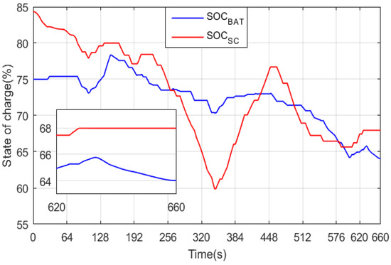
Figure 22.
Battery and supercapacitor state of charge.
7. Real Time Simulation
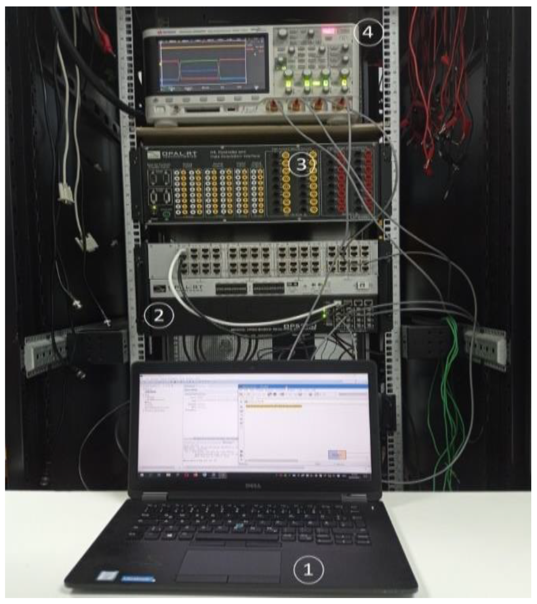
The proposed soft transition strategy was executed in real-time using the OPAL-RT LAB simulator. As shown in Figure 23, the HEV simulation system was first split into a master computation bloc (SM_computation) and user interface console (SC_GUI) bloc, which show the effect control signal variations. The computation subsystem was executed in real-time on one of the CPU cores of the real-time target. Data between the computation subsystem and GUI subsystem were exchanged asynchronously through the TCP/IP link. Figure 24 shows the real time simulation bench established in our research laboratory, in which element 1 represents the host PC, element 2 shows the FPGA-based real time simulator (OP 5700), element 3 highlights the unit measurement of the data acquisition interface (OP 8660), and element 4 is the oscilloscope.
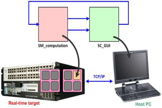
Figure 23.
RT LAB bloc simulation scheme.
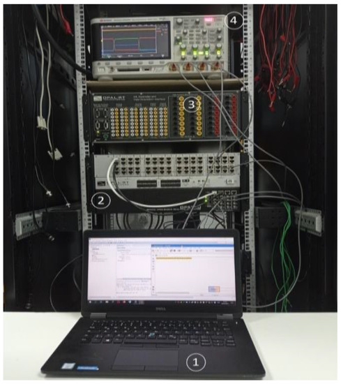
Figure 24.
Test bench (1) Host PC (2) OP5700 (3) OP8660 (4) Oscilloscope.
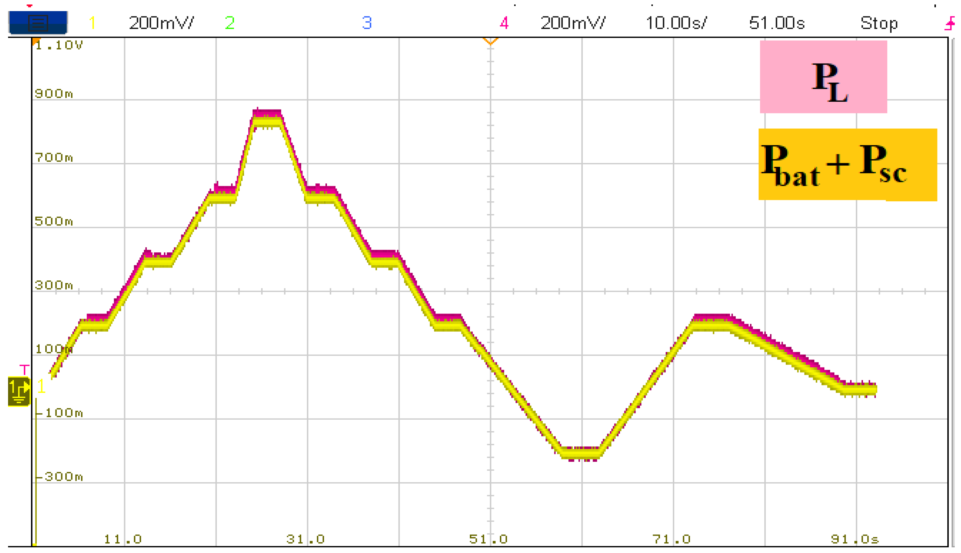
Figure 25 shows the load power required by the HEV, as well as the power developed by the battery and supercapacitor. It can be seen that the power developed by the HEV power sources follows its reference precisely. Furthermore, it is worth noting that a simple load power profile was chosen to clearly show each power source’s power contribution.
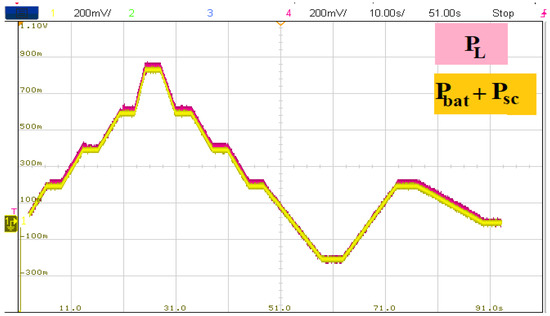
Figure 25.
Load and developed HEV power.
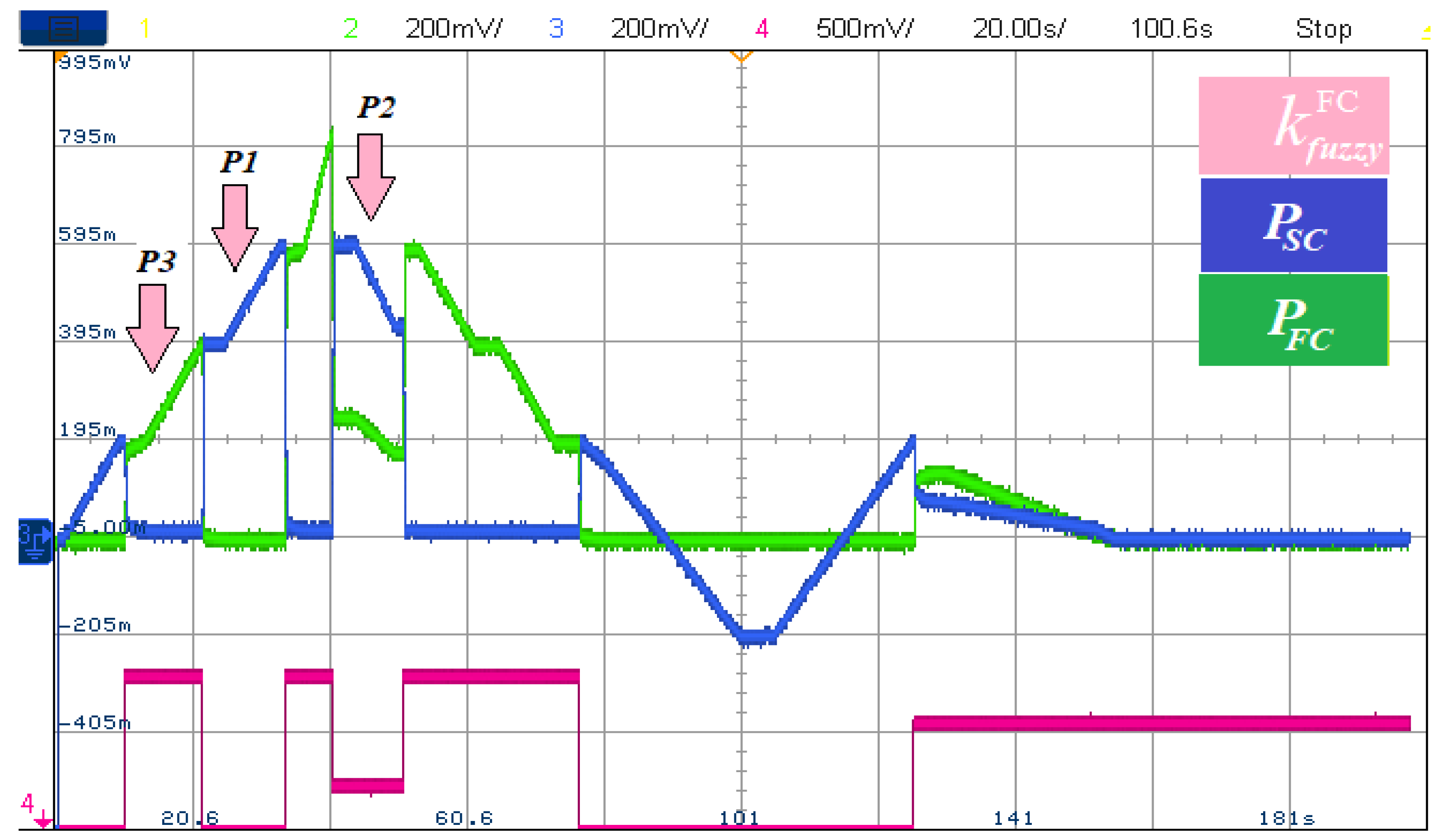
Figure 26 shows the power developed by each power source along with the FC control signal that represents the amount of total power that FC delivers at each time instant. From Figure 24, at P1, when , FC is off and delivers no power. At P2 and this will make the FC delivers 30% of the required power for traction and the SC will ensure the remaining power. At P2 meaning that FC will deliver all the required power for traction.

Figure 26.
Fuel cell and supercapacitor powers.
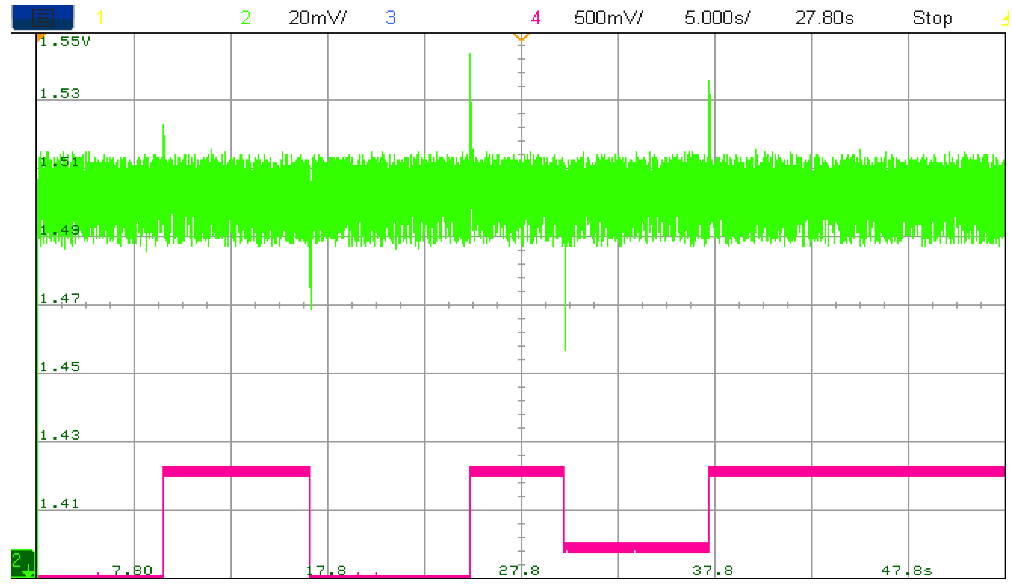
Figure 27 depicts the DC bus voltage Vdc in green color along with FC power control signal in fuchsia color. It can be seen that each time FC toggles from one operating point to another, significant and acceptable DC bus ripples occur.
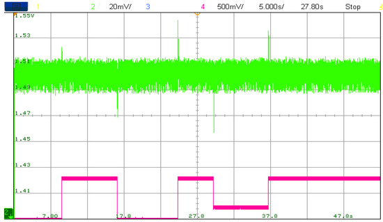
Figure 27.
DC bus voltage.
8. Conclusions
In this work, hybrid electric vehicle controllers were simultaneously tuned using a genetic algorithm with minimization of PMSM torque and speed ripples as an optimization goal. The simulation results show a significant reduction in PMSM torque and speed ripples. This reflects the effectiveness of the cost function formulated in this paper, mainly to tradeoff between torque and speed ripple minimization. The developed fuzzy energy management strategy proposed in this paper operates the battery and the supercapacitor at safe operating points and enables different driving modes. The fuzzy power management used here equilibrated the battery and the supercapacitor’s use and prevented exhausting one power source over another. Both numerical results obtained using MATLAB/Simulink and the real time simulation results obtained using the RT LAB simulator are satisfactory. As further work, we intend to take advantage of the superiority of metaheuristic algorithms in order to ensure optimal use of vehicle power sources, which will result in increasing their lifespan and vehicle autonomy.
Author Contributions
Conceptualization, A.O., N.T. and T.R.; data curation, A.O., N.T. and T.R.; formal analysis, A.O., H.A., N.T., T.R. and S.S.M.G.; funding acquisition, H.A., A.S.B.H. and S.S.M.G.; investigation, H.A., A.S.B.H. and S.S.M.G.; methodology, A.O., N.T. and T.R.; project administration, H.A., A.S.B.H. and S.S.M.G.; resources, S.S.M.G.; software, A.O.; supervision, N.T. and T.R.; validation, A.S.B.H. and S.S.M.G.; visualization, H.A.; writing—original draft, A.O., N.T. and T.R.; writing—review and editing, H.A., A.S.B.H. and S.S.M.G. All authors have read and agreed to the published version of the manuscript.
Funding
This work was supported in part by the Taif University Researchers Supporting Project number (TURSP-2020/34).
Institutional Review Board Statement
Not applicable.
Informed Consent Statement
Not applicable.
Data Availability Statement
Not applicable.
Acknowledgments
The authors appreciate Taif University Researchers Supporting Project number (TURSP-2020/34), Taif University, Taif, Saudi Arabia, and the General Directorate of Scientific Research and Technological Development (DGRSDT) of Algeria.
Conflicts of Interest
The authors declare no conflict of interest.
Abbreviations
| HEV | Hybrid electric vehicle |
| EV | Electric vehicle |
| FC | Fuel cell |
| DC | Direct current |
| RT | Real time |
| PMSM | Permanent magnet synchronous machine |
| DTC | Direct torque control |
| SVM | Space vector modulation |
| GA | Genetic algorithm |
| SOC | State of charge |
| FLC | Fuzzy logic control |
| Symbols | |
| Fext | External force [N] |
| Fr | Resistive force [N] |
| Ft | Tractive force [N] |
| Faero | Aerodynamic force [N] |
| Fg | Gravitational force [N] |
| Ftire | Tire force [N] |
| Facc | Acceleration force [N] |
| m | Vehicle mass [kg] |
| a | Vehicle acceleration [m/s2] |
| A | Vehicle front area [m2] |
| Cd | Aerodynamic coefficient [s2/m2] |
| Vwheel | Wheel speed [m/s] |
| Vwind | Wind speed [m/s] |
| ρ | Air density [kg/m3] |
| ta | Vehicle time constant [s] |
| α | Road slope angle |
| Φd | Direct axis flux [Wb] |
| Φq | Quadratic axis flux [Wb] |
| ΦPM | Permanent magnet flux [Wb] |
| Ld | Direct axis inductance [H] |
| Lq | Quadratic axis inductance [H] |
| id | Direct axis current [A] |
| iq | Quadratic axis current [A] |
| Te | Electromagnetic torque [N·m] |
| ϴs | Stator flux angle [°] |
| VDC | DC bus voltage [V] |
| [Sa Sb Sc]T | Inverter switching state vector |
| α, β, γ | Weighting factors |
References
- Stippich, A.; Christoph, B.; Broeck, C.; Sewergin, A.; Wienhausen, A.H.; Neubert, M.; Schülting, P.; Taraborrelli, S.; Hoek, H.V.; Doncker, R.W. Key Components of Modular Propulsion Systems for Next Generation Electric Vehicles. CPSS Trans. Power Electron. Appl. 2017, 2, 249–258. [Google Scholar] [CrossRef]
- Rassõlkin, A.; Vaimann, T.; Kallaste, A.; Kuts, V. Digital twin for propulsion drive of autonomous electric vehicle. In Proceedings of the IEEE 60th International Scientific Conference on Power and Electrical Engineering of Riga Technical University (RTUCON), Riga, Latvia, 7 October 2019; pp. 1–4. [Google Scholar]
- Ye, X.; Lai, F.; Huo, Z. Energy Management Strategy Design and Simulation Validation of Hybrid Electric Vehicle Driving in an Intelligent Fleet. Electronics 2019, 8, 1516. [Google Scholar] [CrossRef] [Green Version]
- Li, G.; Sun, Q.; Boukhatem, L.; Wu, J.; Yang, J. Intelligent Vehicle-to-Vehicle Charging Navigation for Mobile Electric Vehicles via VANET-Based Communication. IEEE Access 2019, 7, 170888–170906. [Google Scholar] [CrossRef]
- Marzbani, H.; Khayyam, H.; To, C.N.; Quoc, Đ.V.; Jazar, R.N. Autonomous Vehicles: Autodriver Algorithm and Vehicle Dynamics. IEEE Trans. Veh. Technol. 2019, 68, 3201–3211. [Google Scholar] [CrossRef]
- Cho, W.; Choi, J.; Kim, C.; Choi, S.; Yi, K. Unified chassis control for the improvement of agility, maneuverability, and lateral stability. IEEE Trans. Veh. Technol. 2012, 61, 1008–1020. [Google Scholar] [CrossRef]
- Abdelli, R.; Rekioua, D.; Rekioua, T. Performances improvements and torque ripple minimization for VSI fed induction machine with direct control torque. ISA Trans. 2011, 50, 213–219. [Google Scholar] [CrossRef] [PubMed]
- Taib, N.; Metidji, B.; Rekioua, T.; François, B. Novel low-cost self-powered supply solution of bidirectional switch gate driver for matrix converters. IEEE Trans. Ind. Electron. 2011, 59, 211–219. [Google Scholar] [CrossRef]
- Metidji, B.; Taib, N.; Baghli, L.; Rekioua, T.; Bacha, S. Novel single current sensor topology for venturini controlled direct matrix converters. IEEE Trans. Power Electron. 2012, 28, 3509–3516. [Google Scholar] [CrossRef]
- Wu, G.; Zhang, X.; Dong, Z. Powertrain architectures of electrified vehicles: Review, classification and comparison. J. Frankl. Inst. 2015, 352, 425–448. [Google Scholar] [CrossRef]
- Chan, A.C.-F.; Zhou, J. A Secure, Intelligent Electric Vehicle Ecosystem for Safe Integration with the Smart Grid. IEEE Trans. Intell. Transp. Syst. 2015, 16, 3367–3376. [Google Scholar] [CrossRef]
- Kong, W.; Luo, Y.; Qin, Z.; Qi, Y.; Lian, X. Comprehensive Fault Diagnosis and Fault-Tolerant Protection of In-Vehicle Intelligent Electric Power Supply Network. IEEE Trans. Veh. Technol. 2019, 68, 10453–10464. [Google Scholar] [CrossRef]
- Eiza, M.H.; Shi, Q.; Marnerides, A.K.; Owens, T.; Ni, Q. Efficient, Secure, and Privacy-Preserving PMIPv6 Protocol for V2G Networks. IEEE Trans. Veh. Technol. 2018, 68, 19–33. [Google Scholar] [CrossRef]
- Sarić, A.; Marjanović, A.L. Nonlinear optimization of proportional-integral controller in doubly-fed induction generator using the Gradient Extremum Seeking algorithm. Serb. J. Electr. Eng. 2019, 16, 61–180. [Google Scholar] [CrossRef] [Green Version]
- Son, B.; Kim, J.S.; Kim, J.W.; Kim, Y.J.; Jung, S.Y. Adaptive Particle Swarm Optimization Based on Kernel Support Vector Machine for Optimal Design of Synchronous Reluctance Motor. IEEE Trans. Magn. 2019, 55, 1–5. [Google Scholar] [CrossRef]
- Safari, A.; Sheibai, D.M. Artificial Bee Colony Algorithm for Economic Load Dispatch with Wind Power Energy. Serb. J. Electr. Eng. 2019, 13, 61–180. [Google Scholar] [CrossRef]
- Manikanta, G.; Mani, A.; Singh, H.P.; Chaturvedi, D.K. Adaptive Quantum-Inspired Evolutionary Algorithm for Optimizing Power Losses by Dynamic Load Allocation on Distributed Generators. Serb. J. Electr. Eng. 2019, 16, 325–357. [Google Scholar] [CrossRef] [Green Version]
- Tazerart, F.; Mokrani, Z.; Rekioua, D.; Rekioua, T. Direct torque control implementation with losses minimization of induction motor for electric vehicle applications with high operating life of the battery. Int. J. Hydrog. Energy 2015, 40, 13827–13838. [Google Scholar] [CrossRef]
- Gao, W. Performance comparison of a fuel cell-battery hybrid powertrain and a fuel cell-ultracapacitor hybrid powertrain. IEEE Trans. Veh. Technol. 2005, 54, 846–855. [Google Scholar] [CrossRef]
- Araria, R.; Berkani, A.; Negadi, K.; Marignetti, F.; Boudiaf, M. Performance Analysis of DC-DC Converter and DTC Based Fuzzy Logic Control for Power Management in Electric Vehicle Application. J. Eur. Des Systèmes Autom. 2020, 53, 1–9. [Google Scholar] [CrossRef] [Green Version]
- Ouari, K.; Rekioua, T.; Ouhrouche, M. Real time simulation of nonlinear generalized predictive control for wind energy conversion system with nonlinear observer. ISA Trans. 2014, 53, 76–84. [Google Scholar] [CrossRef]
- Oubelaid, A.; Taib, N.; Rekioua, T. Novel coordinated power sources switching strategy for transient performance enhancement of hybrid electric vehicles. COMPEL Int. J. Comput. Math. Electr. Electron. Eng. 2022. [Google Scholar] [CrossRef]
- Oubelaid, A.; Albalawi, F.; Rekioua, T.; Ghoneim, S.S.M.; Taib, N.; Abdelwahab, S.A.M. Intelligent Torque Allocation Based Coordinated Switching Strategy for Comfort Enhancement of Hybrid Electric Vehicles. IEEE Access 2022, 10, 58097–58115. [Google Scholar] [CrossRef]
- Rekioua, D.; Mokrani, Z.; Rekioua, T. Control of fuel cells-electric vehicle based on direct torque control. Turk. J. Electromech. Energy 2018, 3, 8–14. [Google Scholar]
- Oubelaid, A.; Taib, N.; Rekioua, T. Performance Assessment of a Direct Torque Controlled Electric Vehicle considering Driving Cycles and Real Load Conditions. In Proceedings of the 2019 International Conference on Advanced Electrical Engineering (ICAEE), Algiers, Algeria, 19–21 November 2019; pp. 1–6. [Google Scholar] [CrossRef]
- Mokrani, Z.; Rekioua, D.; Rekioua, T. Modeling, control and power management of hybrid photovoltaic fuel cells with battery bank supplying electric vehicle. Int. J. Hydrog. Energy 2014, 39, 15178–15187. [Google Scholar] [CrossRef]
- Guwahati NPTEL. Module 02: Dynamics of Electric and Hybrid Vehicles, Lesson 3, Motion and Dynamic Equations for Vehicles. Available online: https://spada.uns.ac.id/pluginfile.php/670553/mod_resource/content/1/M2.pdf (accessed on 5 July 2022).
- Shokouhandeh, H.; Kamarposhti, M.A.; Asghari, F.; Colak, I.; Eguchi, K. Distributed Generation Management in Smart Grid with the Participation of Electric Vehicles with Respect to the Vehicle Owners’ Opinion by Using the Imperialist Competitive Algorithm. Sustainability 2022, 14, 4770. [Google Scholar] [CrossRef]
- Oubelaid, A.; Taib, N.; Nikolovski, S.; Alharbi, T.E.A.; Rekioua, T.; Flah, A.; Ghoneim, S.S.M. Intelligent Speed Control and Performance Investigation of a Vector Controlled Electric Vehicle Considering Driving Cycles. Electronics 2022, 11, 1925. [Google Scholar] [CrossRef]
- Chen, G.; Hu, D.; Chien, S.; Guo, L.; Liu, M. Optimizing Wireless Charging Locations for Battery Electric Bus Transit with a Genetic Algorithm. Sustainability 2020, 12, 8971. [Google Scholar] [CrossRef]
- Huang, X.; Li, K.; Xie, Y.; Liu, B.; Liu, J.; Liu, Z.; Mou, L. A novel multistage constant compressor speed control strategy of electric vehicle air conditioning system based on genetic algorithm. Energy 2021, 241, 122903. [Google Scholar] [CrossRef]
- Zaky, A.A.; Fathy, A.; Rezk, H.; Gkini, K.; Falaras, P.; Abaza, A. A Modified Triple-Diode Model Parameters Identification for Perovskite Solar Cells via Nature-Inspired Search Optimization Algorithms. Sustainability 2021, 13, 12969. [Google Scholar] [CrossRef]
- Jamil, M.; Yang, X.S. A literature survey of benchmark functions for global optimization problems. arXiv 2013, arXiv:1308.4008. [Google Scholar]
- Hussain, K.; Salleh, M.N.M.; Cheng, S.; Naseem, R. Common Benchmark Functions for Metaheuristic Evaluation: A Review. JOIV Int. J. Informatics Vis. 2017, 1, 218–223. [Google Scholar] [CrossRef]
- Kudela, J.; Matousek, R. New Benchmark Functions for Single-Objective Optimization Based on a Zigzag Pattern. IEEE Access 2022, 10, 8262–8278. [Google Scholar] [CrossRef]


Publisher’s Note: MDPI stays neutral with regard to jurisdictional claims in published maps and institutional affiliations. |
© 2022 by the authors. Licensee MDPI, Basel, Switzerland. This article is an open access article distributed under the terms and conditions of the Creative Commons Attribution (CC BY) license (https://creativecommons.org/licenses/by/4.0/).