1. Introduction
Time synchronization is required to maintain high precision for distributed systems in many application domains, such as automation, testing and measurement, and telecommunications. The applications commonly use communication networks that link the distributed network nodes rather than building a dedicated synchronization infrastructure. Clocks in the distributed systems are then synchronized by means of dedicated messages and protocols. Two prevalent protocols are used for clock synchronization in these networks: Network Time Protocol (NTP) [
1] and Precision Time Protocol (PTP) [
2]. The NTP is widely used to synchronize computer clocks on the Internet. The purpose of the NTP is to convey timekeeping information from several primary servers to secondary time servers and clients via both private networks and the public Internet. Servers and clients are configured in such a way that values flow toward clients from the primary servers at the root via branching secondary servers [
1,
3]. While there can be multiple NTP servers within the synchronized subnet, there is no election to determine the master as there is with other time protocols, such as the PTP. The expected synchronization depends on network distances, wide area networks are at about 10 ms, while local area networks are routinely at 1 ms [
4]. For distributed computer networks in information technology (IT) environments, this is sufficient. However, several Ethernet-based real-time networks in other domains, such as automatic control systems or substation automation systems, require higher synchronization accuracies. In these systems, accuracies in the μs range are often desired, and the number of nodes can be in the range of hundreds. To meet these needs, the PTP was designed and specified in the IEEE 1588 protocol [
2]. IEEE 1588 is a standard protocol for synchronizing independent clocks that run on separate nodes of a distributed measurement and control system [
5]. As the clock synchronization protocol specified in IEEE 1588, the PTP provides a mechanism for synchronizing the clocks of participating nodes in a system to a high degree of accuracy and precision [
2]. The PTP defines several different kinds of clocks, as follows:
Ordinary clock (OC): An OC only has one PTP port. The OC can be the grandmaster (GM) in a system, or it can be a slave clock in the master-slave hierarchy.
Boundary clock (BC): A BC typically has several PTP ports. It can function as both a master and a slave in the master-slave hierarchy.
Transparent clock (TC): A TC forwards all PTP messages just as it does in a normal switch or router.
The PTP is based on a straightforward master-slave synchronization principle. There are two phases in the normal execution of the PTP: (1) establishing a master-slave synchronization hierarchy and (2) synchronizing the clocks. In the first phase, clocks in a PTP system are organized into a master-slave synchronization hierarchy, also known as a master-slave hierarchy, with the GM clock at the top of the hierarchy determining the reference time for the entire system. In the second phase, the synchronization is achieved by exchanging PTP timing messages, with the slaves using the timing information to adjust their clocks to the time of their master in the hierarchy. PTP uses the best master clock (BMC) algorithm to establish the master-slave hierarchy for a network. Only OCs and BCs run the BMC algorithm to build the hierarchy; TCs do not participate in establishing the hierarchy. After an OC runs the BMC algorithm, its port can be in a master state or a slave state. If the port is in a master state, the OC is the GM of the PTP system. Otherwise, the OC will be a slave in the hierarchy. The master-slave hierarchy is mainly established based on BCs in the network. The BMC algorithm divides the clocks in the network into master clocks and slave clocks. Slave clocks synchronize their local clocks with the time of their master clocks. However, the BMC algorithm has the following issues:
The master-slave hierarchy established by the BMC algorithm sometimes contains several BCs that have too many slaves. This type of hierarchy is known as the unbalanced master-slave hierarchy or the unbalanced hierarchy. In the unbalanced hierarchy, clocks with many slaves may experience a high communication load when exchanging PTP messages with their slaves, resulting in a high consumption of processing and network bandwidth. Additionally, slaves in the master-slave hierarchy have no spare master. In other words, masters are single points of failure in the hierarchy. Unfortunately, the BMC algorithm does not provide any fast recovery mechanism for the master-slave hierarchy in the case of a master failure. The failure of a master (e.g., device failure or link failure) requires the BMC algorithm to re-elect a new master and re-establish the hierarchy [
6]. The start of a master election is based on timeout; thus, it requires a specific time span during which the clocks are not synchronized so they run freely [
7]. This drawback causes the loss of reference clock synchronization from the GM clock as well as clock drift for the clocks during the re-election of the new master, thereby decreasing the network’s clock synchronization performance.
Several approaches have been proposed to provide fast recovery mechanisms in case of a master failure for the PTP. Gaderer et al. [
8] proposed a democratic approach to enhance the PTP with fault-tolerance and overcome the transient deterioration of synchronization accuracy during recovery from a master failure. In the approach, masters are distributed in a group of nodes with sufficiently accurate clocks. The failure of one group member is not a problem because the group can still find a fault-tolerant time value [
8]. Bondavalli et al. [
9] described a protocol for detecting timing failures for internal synchronization based on a revised version of the reliable and self-aware clock (R&SAClock) software [
10]. The study showed that the system is able to detect all the failures injected on the master under different conditions and correctly identify failures on slaves with a high probability. Cho et al. [
11] proposed enhanced precision time synchronization for wireless sensor networks (WSNs). Valls et al. [
12] proposed an enhanced middleware for real-time reconfiguration of service-oriented distributed real-time systems. The proposed middleware supports time-deterministic reconfiguration in distributed soft real-time environments with a software model based on services. The proposed middleware includes time-bounded reconfiguration and service-based composition algorithms that are built on top of real-time resource management; in contrast to other solutions, this method supports predictable execution [
12]. Valls et al. [
13] also mentioned the need for timing requirements for real-time applications in real-time virtualization and cloud computing technology.
However, no previous study has solved the issue of the unbalanced master-slave hierarchy generated by the BMC algorithm. In this paper, we propose the balanced synchronization hierarchy with spare masters (BSHSM) algorithm to solve both of the BMC algorithm issues mentioned above. The BSHSM algorithm establishes a balanced master-slave synchronization hierarchy for the PTP. In addition, it also provides a fast recovery mechanism for PTP in the case of master failures by electing a spare master for each slave. Thus, the BSHSM algorithm enhances the synchronization performance of the PTP. The contribution of the proposed BSHSM algorithm can be summarized as follows:
The remainder of this paper is organized as follows:
Section 2 introduces the PTP and its BMC algorithm.
Section 3 describes the proposed BSHSM algorithm.
Section 4 presents information on various simulations and their results to evaluate and compare the performance of the BSHSM and BMC algorithms. Finally, conclusions are presented in
Section 5.
2. The BMC Algorithm
2.1. Overview
To build a synchronization hierarchy, the PTP permits the use of one of the following two options [
10]:
By default, the BMC algorithm;
An alternate algorithm, if specified in a PTP profile.
The BMC algorithm compares datasets describing two clocks to determine which describes the better clock. The BMC algorithm is run locally in OCs and BCs to determine which clock is better. By running the BMC algorithm locally, clocks do not need to negotiate which clock should be the master and which clock should be the slaves. Instead, each clock only computes the state of its own ports [
10]. The BMC algorithm analyzes and compares the contents of the
Announce messages received by clocks and datasets associated with the clocks to determine the state of each port of the clocks.
2.1.1. Port States
Each OC and BC port maintains a separate copy of the PTP state machine. This state machine defines the allowed states of the port and the transition rules between the states. The port states that determine the master-slave hierarchy include:
Master: The master port is the source of time on the path served by the port.
Slave: The slave port synchronizes to the clock on the path with the port that is in the master state.
Passive: The passive port is not the master on the path, and it does not synchronize to a master.
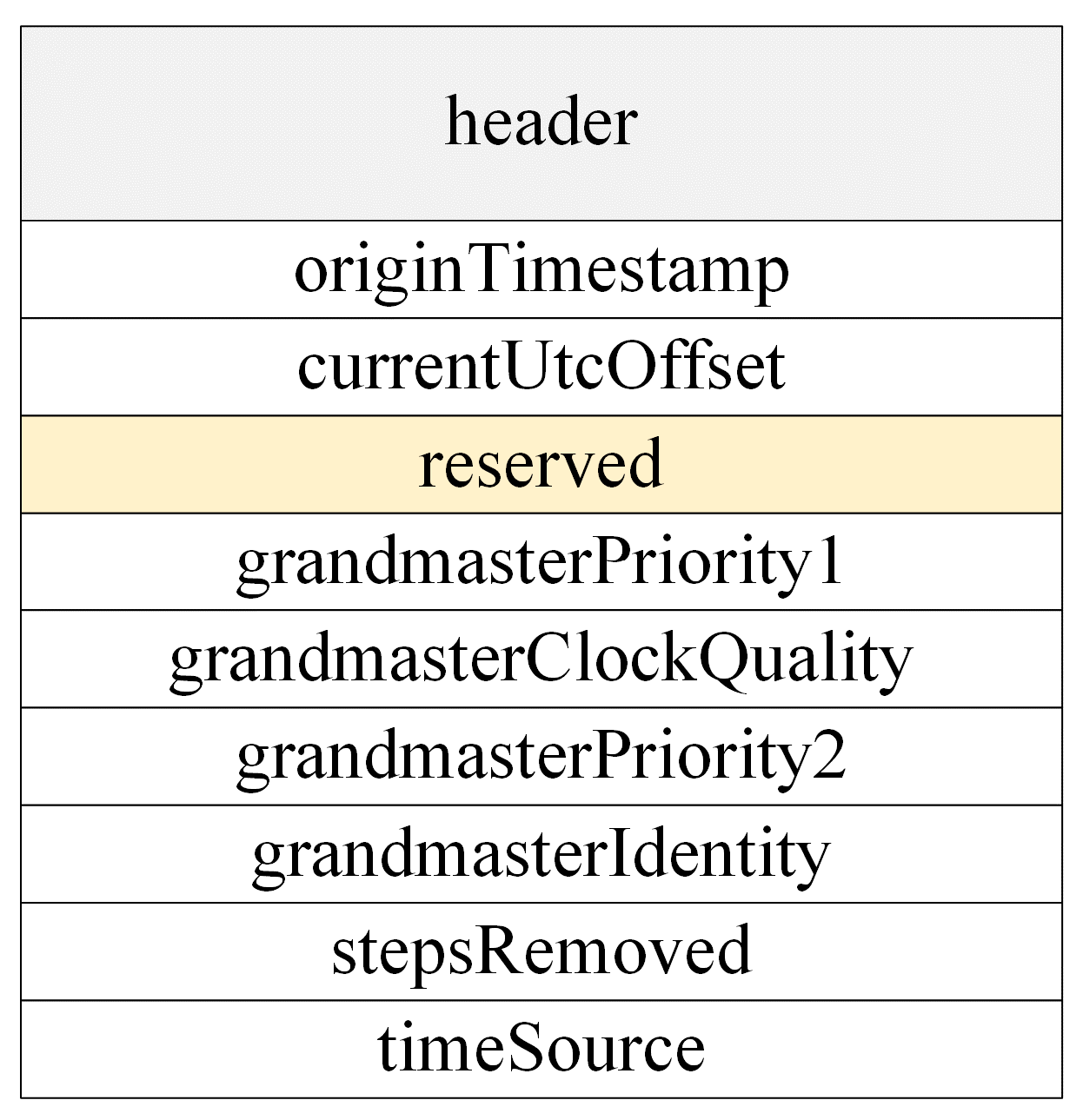
2.1.2. Announce Messages
The BMC algorithm works based on the data contained in the Announce messages received by a given clock and on the datasets maintained by the local clock. Announce messages provide status and characterization information about the transmitting clock and its GM. The information is used by the receiving node when executing the BMC algorithm.
grandmasterPriority1: the value of the parentDS.grandmasterPriority1 of the transmitting clock.
grandmasterClockQuality: the value of the parentDS.grandmasterClockQuality of the transmitting clock.
grandmasterPriority2: the value of the parentDS.grandmasterPriority2 of the transmitting clock.
grandmasterIdentity: the value of the parentDS.grandmasterIdentity of the transmitting clock.
stepsRemoved: the value of the currentDS.stepsRemoved of the transmitting clock.
The structure of an
Announce message is shown in
Figure 1.
2.1.3. Datasets
OCs and BCs locally maintain datasets, including defaultDS, currentDS, parentDS, timePropertiesDS, and portDS, that are used by the BMC algorithm to establish the master-slave hierarchy for the PTP. It is important to note that only datasets and their attributes used by the BMC algorithm are described in this paper.
defaultDS: The defaultDS is the default dataset that describes the attributes of the local clock.
The members of the defaultDS dataset are:
defaultDS.clockIdentity: the clockIdentity of the local clock;
defaultDS.numberPorts: the number of PTP ports on the clock;
defaultDS.clockQuality: the member consists of clockClass and clockAccuracy of the clock;
defaultDS.priority1: the priority1 attribute of the local clock;
defaultDS.priority2: the priority2 attribute of the local clock.
currentDS: The currentDS is the current dataset that contains the current properties of the local clock. The dataset contains the following members:
parentDS: The parentDS is the parent dataset that contains information of the current master of the clock. The dataset contains the following members:
parentDS.parentPortIdentity: the portIdentity of the port on the master;
parentDS.grandmasterIdentity: the clockIdentity attribute of the GM clock;
parentDS.grandmasterClockQuality: the clockQuality attribute of the GM clock;
parentDS.grandmasterPriority1: the priority1 attribute of the GM clock;
parentDS.grandmasterPriority2: the priority2 attribute of the GM clock.
portDS: The portDS is the port dataset that characterizes a PTP port. Each OC or BC port maintains one portDS dataset. Some members of the dataset are:
2.2. The BMC Algorithm
The BMC algorithm is used to determine the synchronization hierarchy among OCs and BCs in a network. It classifies the clocks into master clocks and slave clocks. Slave clocks trace the frequency and time of the master clocks. Since OCs only have one port, they are always slave clocks in the master-slave hierarchy, except for the GM. Therefore, the main purpose of the BMC algorithm is to establish the synchronization hierarchy for BCs. In terms of networks, the BMC algorithm establishes the synchronization hierarchy with the GM as the root of the hierarchy. In term of nodes, the BMC algorithm determines the master clock for each BC.
The BMC algorithm selects the best master clock by comparing the data contained in the Announce messages received from different ports and the datasets describing the local clock. If the local clock is selected as the best master clock, the local clock functions as the GM. If an external clock is selected as the best master clock, the local clock traces the master clock.
The BMC algorithm consists of two separate algorithms:
A dataset comparison algorithm that compares the datasets of clocks and the data of received Announce messages to determine the best clock;
A state decision algorithm that computes and assigns the state for each port involved.
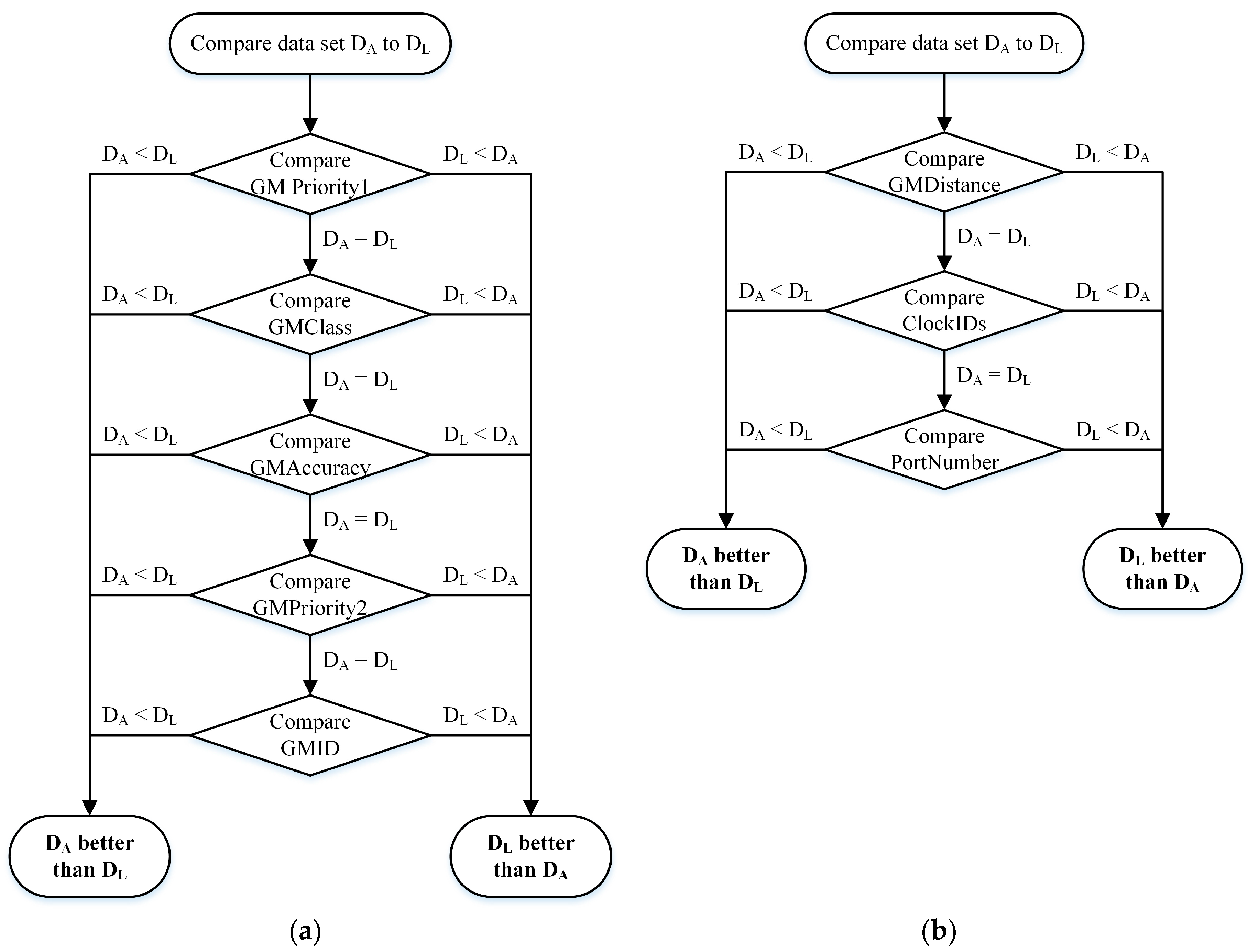
In the dataset comparison phase, the BMC algorithm compares one clock with another by comparing the datasets representing those clocks. Dataset comparison algorithms are shown in
Figure 2a,b. As shown, the datasets are indicated as
and
, where
is the dataset of the received
Announce message and
is the dataset of the local clock.
Figure 2a shows the dataset comparison algorithm of two clocks that have different GM clocks, whereas
Figure 2b shows the dataset comparison algorithm of two clocks that have the same GM clock.
The information sources for the dataset values in the BMC algorithm are presented in
Table 1.
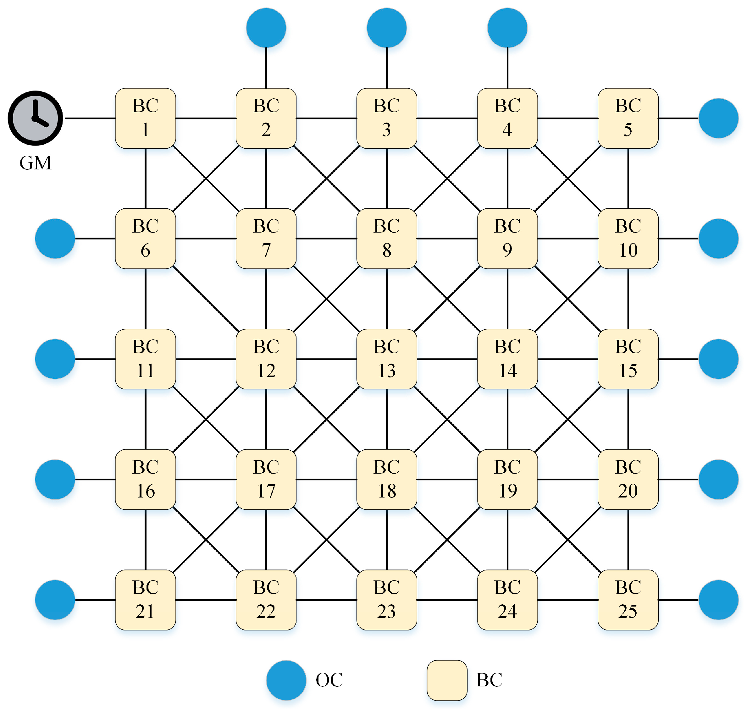
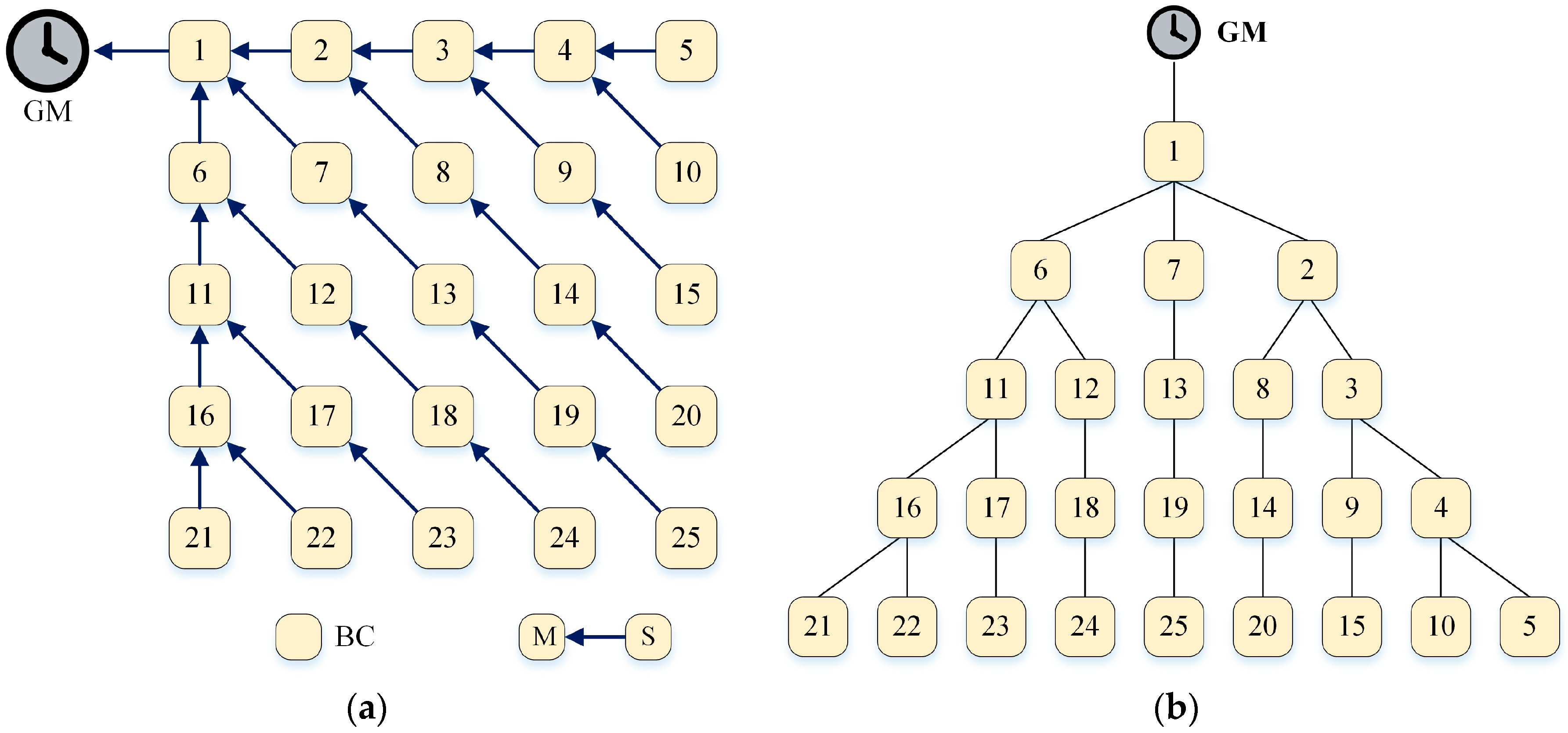
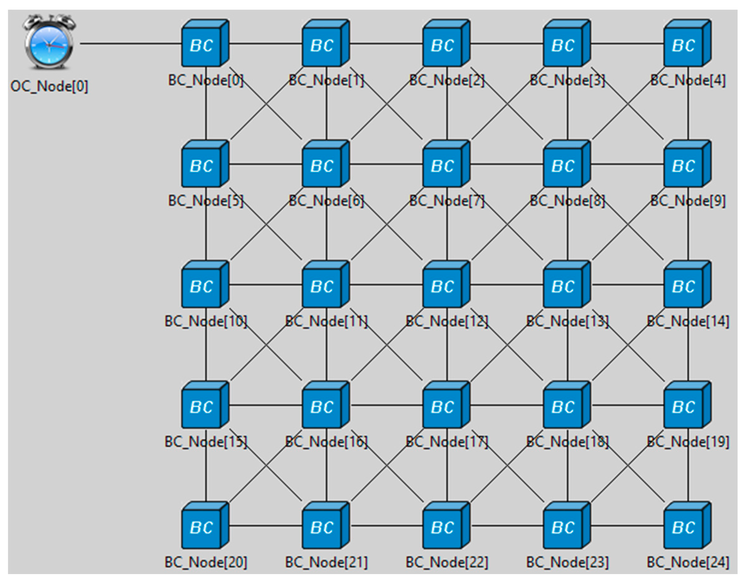
Figure 3 shows a sample PTP network that has one GM clock and several OCs and BCs.
OCs are slave clocks that synchronize time to their masters that are the BCs to which the OCs are connecting. Since the OCs are always slaves in the master-slave hierarchy, the main task of the BMC algorithm is to establish a synchronization hierarchy for the GM and the BCs in the network. Therefore, in this paper, we focus on establishing the master-slave hierarchy for BCs.
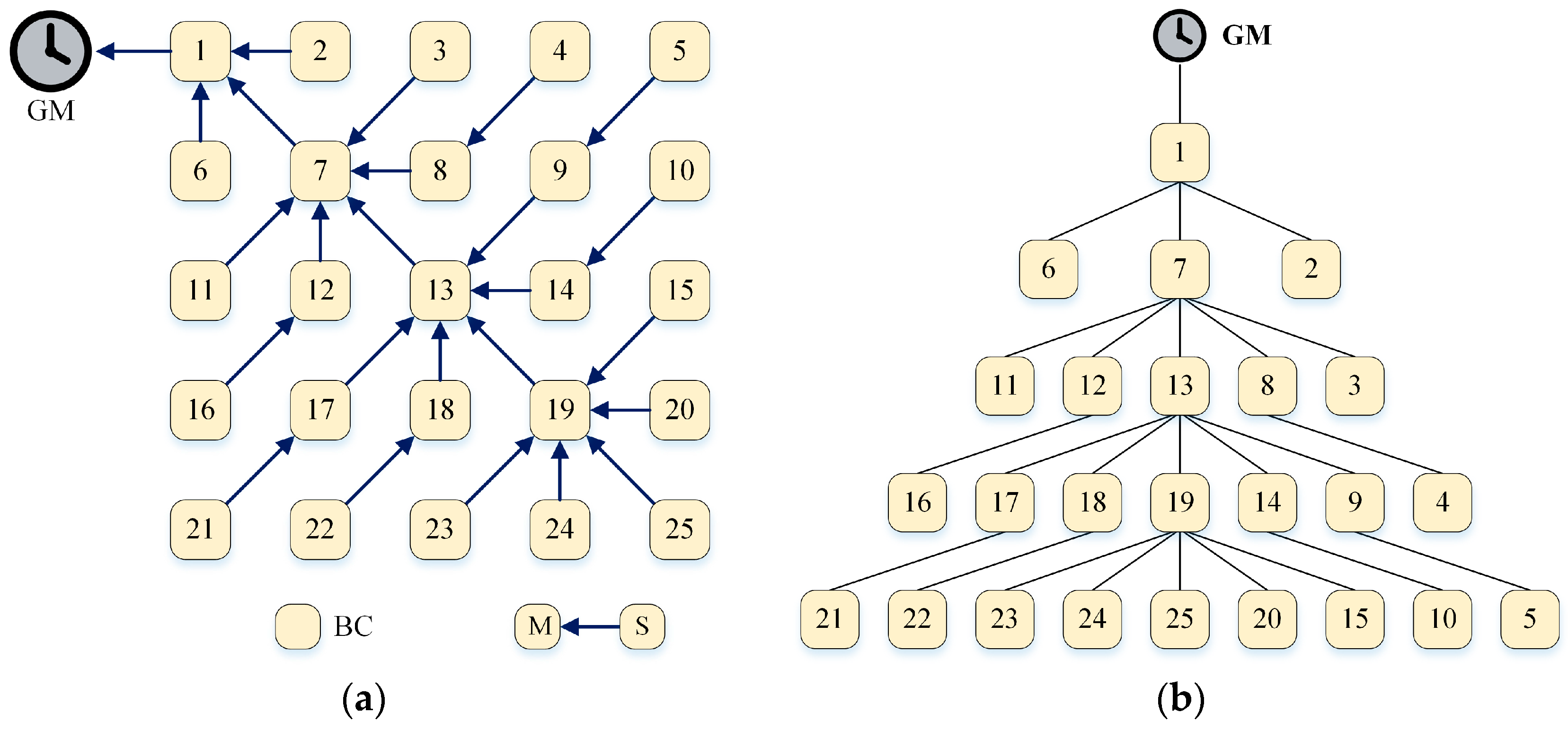
After clocks independently execute the BMC algorithm, a master-slave hierarchy of the sample network is created (
Figure 4a). The hierarchy can be represented as a synchronization tree (
Figure 4b).
In the sample network, there is only one GM, the comparison algorithm shown in
Figure 2b is used to compare the datasets for each BC. The clock with the lowest
stepsRemoved and
clockIdentity is selected as the best master clock.
For the sample network, BCs 3, 8, 11, 12, and 13 have the same
stepsRemoved value; and BC 13 has the lowest
clockIdentity value, whereas BC 3 and BC 11 have the highest
clockIdentity value. Since the sample network has one GM, the BMC algorithm compares the clocks based on the
stepsRemoved and
clockIdentity values. After all the clocks locally run the BMC algorithm, BC 13 has five slaves, BC 8 and BC 12 have only one slave, and BC 3 and BC 11 have no slaves (
Figure 4). The example illustrates that the BMC algorithm does not balance the number of slaves in BCs. In other words, some of the BCs have many slaves, whereas others only have a few. A BC with many slaves has a higher load than a BC with few slaves. As a result of this unbalanced hierarchy, BC 13 has to exchange too many messages with its slaves, resulting in the high consumption of processing and network bandwidth.
Additionally, the BMC algorithm does not provide any fast recovery scheme for the master-slave hierarchy in the case of a master failure. Thus, a slave in the hierarchy will lose its synchronization source if its current master has failed or is disconnected. For example, if the link between BC 13 and BC 19 has failed, BC19 will lose its current master (BC 13), and it must change to the free-running mode.
3. The BSHSM Algorithm
Previous studies have mainly focused on providing a recovery mechanism for the PTP in the case of master failures. However, no study has solved the unbalanced master-slave hierarchy issue generated by the BMC algorithm. In this paper, we propose a novel BSHSM algorithm to build a balanced master-slave hierarchy with a balanced number of slaves in BCs and to provide a fast recovery mechanism with spare masters in the case of master failure. The BSHSM algorithm consists of the following phases:
3.1. Balanced Synchronization Hierarchy
The comparison algorithm for datasets with different GMs of the BSHSM algorithm is similar to the BMC algorithm. However, in comparison to the BMC algorithm, the BSHSM algorithm enhances the comparison algorithm for datasets with the same GM. To ensure that the number of slaves in the master-slave hierarchy is balanced in clocks, the BSHSM algorithm uses a new numberSlaves attribute to compare the datasets. The value of the numberSlaves attribute of a clock is the number of slaves tracing the clock. To use the numberSlaves attribute in the BSHSM algorithm, the following updates must be made to the datasets of clocks and the structure of the Announce message, as noted below.
3.1.1. Updated Datasets
In the BSHSM algorithm, the new numberSlaves attribute is used to compare datasets and to select the best master clock. The numberSlaves attribute is added to two datasets, including currentDS and parentDS.
1. currentDS dataset
The numberSlaves attribute of currentDS indicates the number of slaves of the local clock. The updated members of the currentDS dataset used in the BSHSM algorithm are as follows:
currentDS.stepsRemoved
currentDS.numberSlaves
2. parentDS.dataset
The numberSlaves attribute of parentDS indicates the number of slaves of the master of the clock. The updated members of the parentDS dataset used in the BSHSM algorithm are as follows:
parentDS.parentPortIdentity
parentDS.grandmasterIdentity
parentDS.grandmasterClockQuality
parentDS.grandmasterPriority1
parentDS.grandmasterPriority2
parentDS.numberSlaves
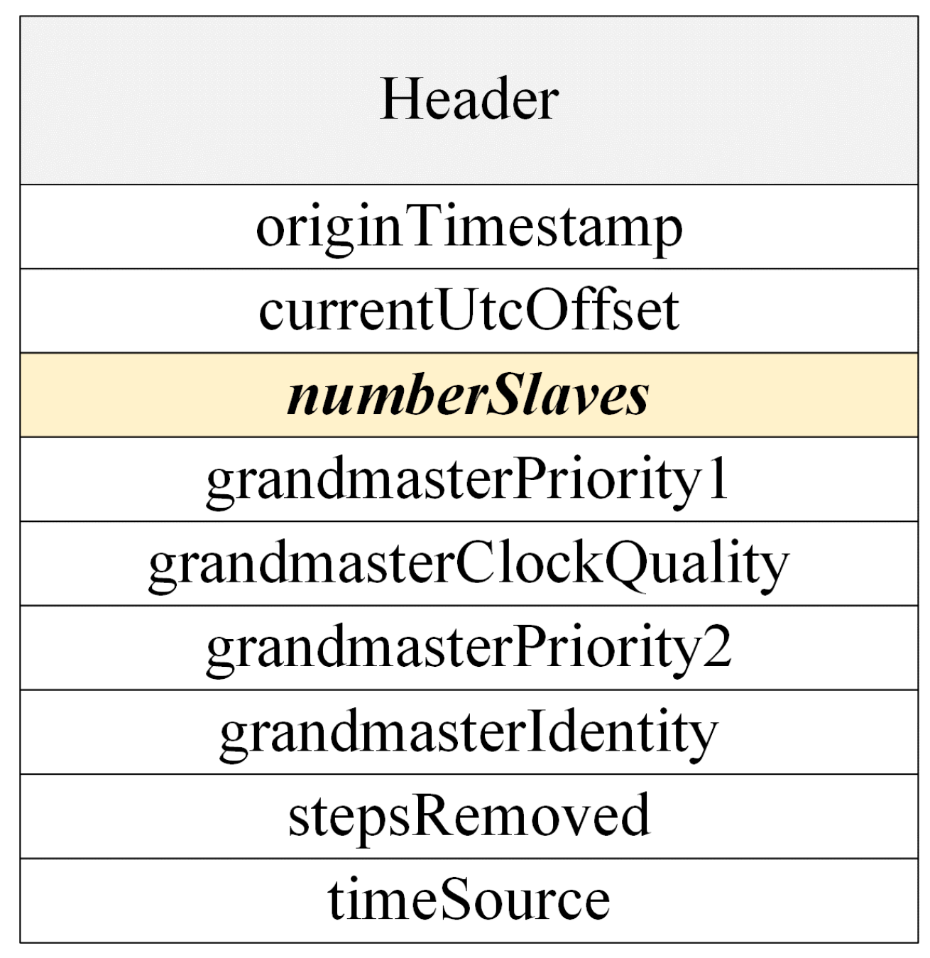
3.1.2. Revised Announce Message
In the BSHSM algorithm, the
reserved field of the original
Announce message is replaced by the new
numberSlaves field.
Figure 5 shows the structure of the revised
Announce field. The
numberSlaves field indicates the value of the
currentDS.numberSlaves of the master clock issuing this
Announce message.
When a master clock sends an Announce message to its slave clocks, it sets the numberSlaves field of this message to the value of its currentDS.numberSlaves attribute. Upon receiving the Announce message, a slave clock uses the value of the numberSlaves field to compare datasets and to select its master clock.
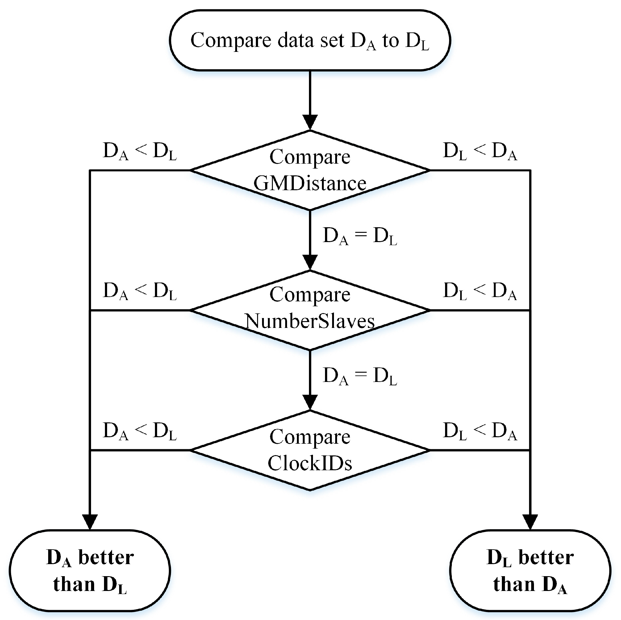
3.1.3. Dataset Comparison Algorithm
To compare datasets that have the same GM, such as the BMC algorithm, the BSHSM algorithm first compares the
stepsRemoved values of the datasets. If the values are the same, the BSHSM algorithm then compares the
numberSlaves values of the datasets instead of comparing the clock identity (
clockID) values, as done by the BMC algorithm. The clock that has the dataset with a lower
numberSlaves value is selected as the best master lock. Finally, if those values are equivalent,
clockIDs are used to compare. The comparison algorithm of the BSHSM algorithm is presented in
Figure 6.
The information sources of the dataset values in the BSHSM algorithm are presented in
Table 2.
After a BC chooses a new master clock, it sends a
masterSEL message to the new master to confirm the election. It also sends a
masterREM message to the previous master to signal that the previous master is no longer its master. Upon receiving the
masterSEL and
masterREM messages, the BC confirms the receipt of the messages by sending back a
masterACK message, and then it updates its
currentDS.numberSlaves value. As seen in the sample network shown in
Figure 3, after running the BSHSM algorithm for BCs, the master-slave hierarchy is established (
Figure 7a).
Figure 7b shows the corresponding synchronization tree of the master-slave hierarchy.
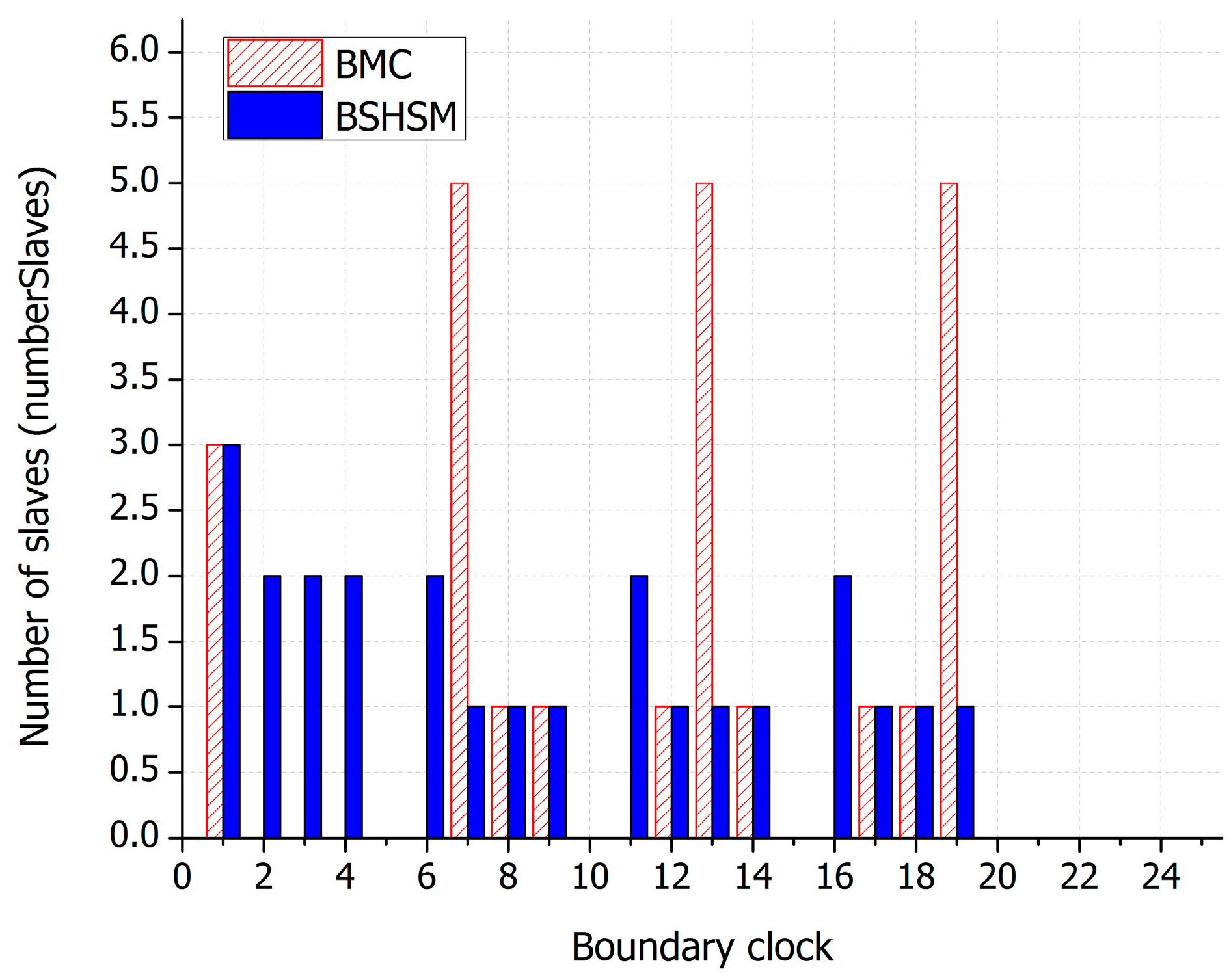
It is clear that, with using the numberSlaves attribute as a criterion to compare and select the best master clock, the BSHSM algorithm establishes a master-slave hierarchy with a balanced number of slaves in clocks. Therefore, the BSHSM algorithm solves the problems caused by the unbalanced master-slave hierarchy, as seen in the BMC algorithm.
3.2. Fast Recovery with a Spare Master
The BMC algorithm does not provide a fast recovery mechanism for clocks in the master failure case. It supports a timeout mechanism defining the announceReceiptTimeoutInterval, with a value of announceReceiptTimeout multiplied by the announceInterval. The value of announceReceiptTimeout specifies the number of accounceIntervals that must pass without the receipt of an Announce message before the ANNOUNCE_RECEIPT_TIMEOUT_EXPIRES event occurs. When the master clock of a BC fails, the BC will not receive Announce messages from its master. The ANNOUNCE_RECEIPT_TIMEOUT_EXPIRES event then occurs at the expiration of this timeout, plus a random number of announceIntervals is uniformly distributed in the range (0, 1). Since the BC has no other port in the slave state, the BMC algorithm updates the port’s datasets to the master state configuration and the BC changes to the free-running mode.
This paper presents a fast recovery mechanism provided by the proposed BSHSM algorithm. To provide fast recovery, the BSHSM algorithm allows each BC to select a spare master clock. The spare master of a BC is the clock with the next best dataset. The comparison algorithm of selecting the spare master clock is the same as that of the BMC algorithm. When a BC loses its current master, it immediately selects its spare master as its new master clock and sends a masterSEL message to the new master. In other words, the BC does not have to change to the free-running mode and re-elect its new master in the case of a master failure. Therefore, the BSHSM algorithm avoids the loss of synchronization, as well as clock drift in the master failure case.
The BSHSM algorithm defines a new spareParentDS dataset for BCs to contain information on the spare master. The spareParentDS dataset members are the same as the parentDS dataset members. Below is a list of some of the members of the spareParentDS dataset used by the BSHSM algorithm:
spareParentDS.parentPortIdentity
spareParentDS.grandmasterIdentity
spareParentDS.grandmasterClockQuality
spareParentDS.grandmasterPriority1
spareParentDS.grandmasterPriority2
spareParentDS.stepsRemove
spareParentDS.numSlaves
The dataset values used by the comparison algorithm of the BSHSM algorithm to select the spare master clock are presented in
Table 3.
The pseudocode of the BSHSM algorithm (Algorithm 1) for establishing the balanced master-slave hierarchy with spare masters is as follows:
| Algorithm 1 BSHSM |
| Compare DA to DP |
| If (DA better than DP) |
| Select DA as the best master clock |
| Update parentDS dataset |
| Else |
| Compare DA to DS |
| If (DA better than DS) |
| Select DA as the spare master clock |
| Update spareParentDS dataset |
Note: DA: dataset of the received Announce message; DP: datasets of the current master clock (parentDS); DS: dataset of the spare master clock (spareParentDS).
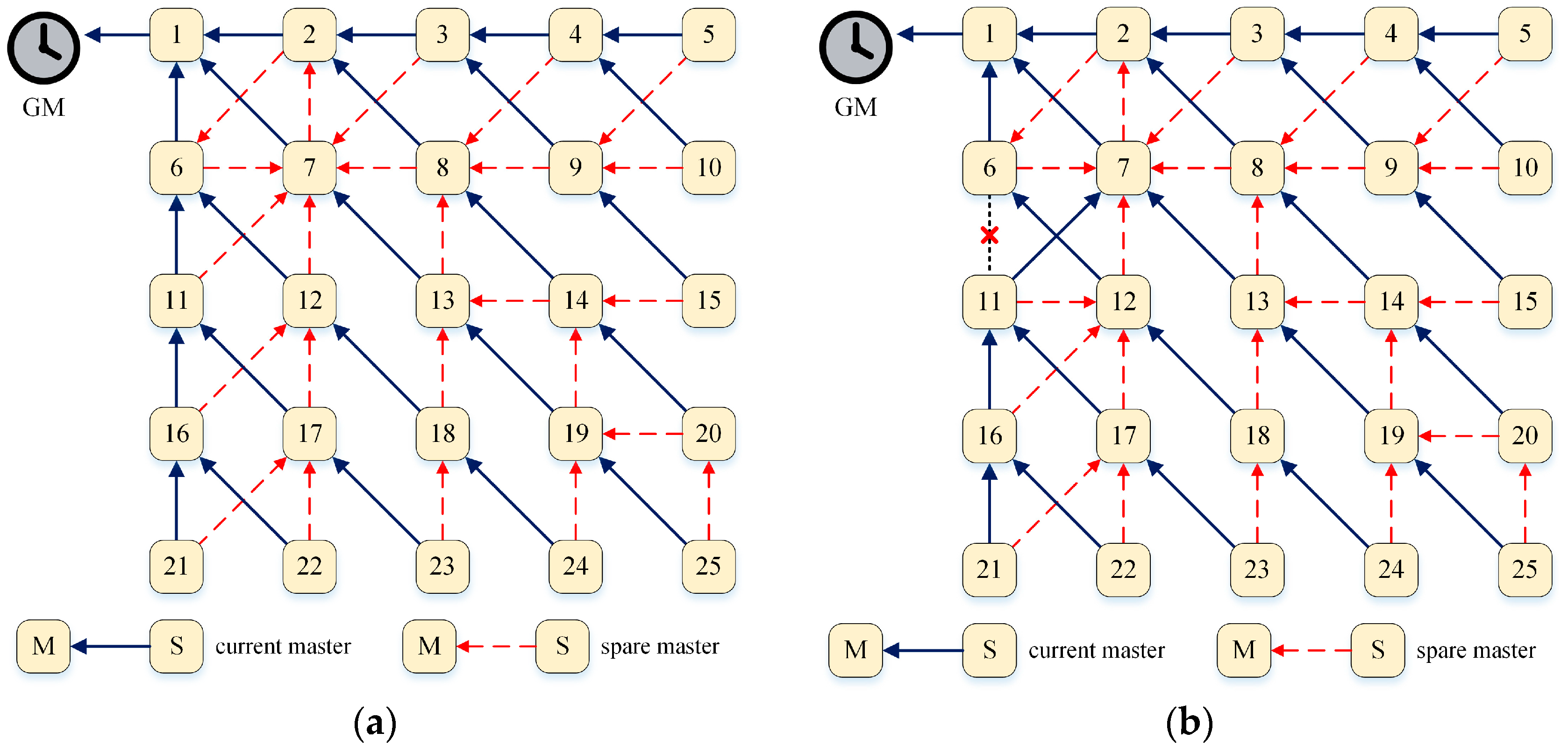
Figure 8a shows the master-slave hierarchy with fast recovery capability established by the BSHSM algorithm of the sample network shown in
Figure 3. If a clock loses its connection to its current master, the clock immediately selects its spare master clock as the new master clock and synchronizes time with the new master. For example, if the link between BC 6 and BC 11 fails, BC 11 loses its current master (BC 6) and immediately selects its spare master (BC 7) as its new master by sending a
masterSEL message to the new master. The clock then compares datasets and selects BC 12 as its new spare master clock, as shown in
Figure 8b.


