Abstract
Partial discharge (PD) measurement and its pattern recognition are vital to fault diagnosis of transformers, especially to those traction substation transformers undergoing repetitive traction load shocks. This paper presents the primary factors induced by traction load shocks including high total harmonics distortion (THD), transient voltage impulse and high-temperature rise, and their effects on the feature parameters of PD. Experimental tests are conducted on six artificial PD models with these factors introduced one by one. Results reveal that the maximum PD quantity and the PD repetitive rate are favorable to be enlarged when the oil temperature exceeds 80 °C or the THD is higher than 16% with certain orders of harmonic. The decline in PD inception voltage can mainly be attributed to the transient voltage impulse. The variation in central frequency of the fast Fourier transformation (FFT) spectra transformed from ultra-high frequency signals can mainly be attributed to high THD, especially when it exceeds 20%. The temperature rise has no significant influence on the FFT spectra; the transient voltage impulse, however, can result in a central frequency shift of the floating particle discharge. With the rapid development of high-speed railways, the study presented in this paper will be helpful for field PD detection and recognition of traction substation transformers in the future.
1. Introduction
Traction substation transformers are one of the key components of the traction power supply and distribution system of a high-speed railway. Presently, the traction substation transformers in service in China are mainly oil-immersed types, like those supplying electrical power for heavy haul freight trains and high-speed passenger trains. During service, the oil/paper insulation of traction substation transformers, compared with general power transformers, must withstand stresses caused by non-periodic and short-time load shocks, high-temperature rises, and transient overvoltages, etc. [1,2,3,4]. Such load characteristics of the traction power supply and distribution system lead to a rapid aging of the traction substation transformers and thus result in various defects in their insulation. Among the failures, partial discharge (PD) has a great impact on the aging of the oil/paper insulation, which may result in a breakdown or even flashover. Therefore, it is essential to investigate the PD properties of traction substation transformers under such operation condition to ensure their safety and reliability.
Different from power transformers, traction substation transformers convert three-phase power (220/110 kV) into two independent single phases (27.5 kV) with equal load capability to supply power to the train. The traction substation transformer is unique in the following aspects:
- The traction substation transformer usually works under an imbalanced load condition, which must withstand a high content of negative sequence current [1].
- The high THD caused by power contact of catenary-pantograph, power converters/inverters, and other power electronic devices [2,3].
- The traction substation transformer always suffers from high-temperature rises caused by short-time overload shocks and surge currents. These shocks generally exhibit high nonlinearity and non-stationary dynamics [4,5].
- During regenerative braking or neutral section passing of the train, transient overvoltages often occur. In the worst case, this will lead to a resonant overvoltage in the traction power supply and distribution system [6].
Under such operation conditions, the technical requirements for traction substation transformers (i.e., limitation of temperature rise, load curves, shortcircuit times, etc.) are much higher compared with those of regular power transformers [7,8,9].
Up to now, studies on the PD characteristics of power transformers have been carried out in both the laboratory and actual field experiments. By means of experimental tests and various signal detection and processing techniques, great progress has been made in PD recognition and diagnosis.
For diagnostic purposes, PD tests were conducted in the laboratory to simulate different PD patterns. It has been revealed by Pompili and Bartnikas et al. [10,11,12] that the PDs in oil-impregnated transformers usually take place in cavities where the electrical field stress is enhanced. Considering the PD patterns are various in the actual field, a number of tests on different types of PDs have been conducted, including:
- Cavity discharge (partial discharge in spherical cavities or gaps within a solid dielectric material) within insulation papers or pressboards [13,14,15,16,17,18,19,20,21],
- Surface discharge in oil [13,14,15,16],
- PD due to floating particles in oil [17,22],
- Air bubble discharge in oil [14,17,22,23],
- PD due to bad grounding (metal-to-metal discharge) [13], and
- Oil wedge or metal protrusions caused PD in pure oil [13,22,24,25,26,27].
It has been proved by Niasar et al. [17] that the PD incipient voltage and the breakdown voltage are directly affected by the degree of aging of the insulation paper due to thermal stresses. Besides, Tsuchie et al. [20] found that the synergistic effect of thermal and electrical stress has a great impact on the PD characteristics. One of the obvious symptoms is the content of byproducts like low molecular weight hydrogen gas dissolved in the oil.
As has been proved, the THD has a considerable influence on PD properties, and which in turn makes the recognition of PD more difficult. The PD incipient voltage would decline with an increase in THD, the PD phase distribution and its amplitude would be distorted, and the statistical parameters would be also affected [21,26]. To observe the PD activity under harmonic AC voltages, metal particles were mixed in oil. Test results demonstrated that the ultra-high frequency PD signal and rising time of the current impulse could be greatly affected due to particle movements [28]. For further consideration, PD performances under high voltage impulse and a combined use of DC and AC voltage were presented in [18,23], where a new approach for PD detection and recognition was proposed.
The foregoing mentioned studies cover most of the PD patterns in both actual field and laboratory. However, rather limited work has been done to explain the influences of different factors that result from field conditions, especially for those traction substation transformers under traction load shocks. Therefore, a PD test platform is established to study the influences of traction load shocks on PD characteristics. The influences of high total harmonic distortion with certain orders of harmonic, high-temperature rise, and transient voltage impulse caused by traction load shocks on feature parameters of PD are then investigated with the six PD models used. The rest of the paper is organized as follows: Section 2 presents the experimental setup and configurations. The PD test results and analysis are given in Section 3, while conclusions and future work suggestions are presented in Section 4.
2. Experimental Setup
The PD test platform, which includes six artificial PD models, is shown in Figure 1. This test platform consists a high voltage generation unit, a PD simulation system, and some measurement facilities. Details will be described in the following sections.
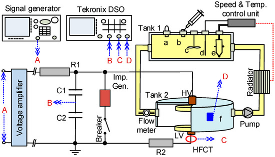
Figure 1.
Schematic diagram for PD test, where (a) pressure relief valve, (b) injection port, (c) blender, (d) thermometer, (e) heater and (f) UHF sensor. The red letters A, B, C, and D stand for different kind of signals.
2.1. Test Platform Configurations
In this paper, three factors resulting from traction load shocks are considered, including high THD with certain orders of harmonic, high-temperature rise, and transient voltage impulse.
2.1.1. High Voltage Generation Unit
The high voltage waveforms utilized for PD tests included: (i) pure AC voltage at 50 Hz, (ii) AC voltage at 50 Hz containing harmonics with different THDs, and (iii) transient square impulses in microseconds. The AC voltage and harmonics are produced by a digital synthesis function generator (type SFG-830, GWINSTEK, Taibei, Taiwan, China) with adjustable frequency, amplitude and THD. The square impulse voltage, with controllable frequency and duty cycle, is generated by a unipolar square voltage impulse generator (type PITS7001, Zhiyuan Electrical Co., Chengdu, China) with a rising edge of 2 µs. For the circuit of this readers can refer to [25]. The harmonics contained in the AC voltage are denoted as [24]:
where Vm is the RMS value of v(t), 20 V in this study, ω stands for the angular frequency, φ is the phase shift, K is the ratio of the harmonic peak voltage to the fundamental frequency voltage, and h is the harmonic order.
Denoting Vh (h = 3, 5, …, 2n+1) and V1 as the RMS values of the harmonic voltage and fundamental frequency voltage, respectively. The THD can be calculated using the following expression:
Thus, AC voltages with different THDs can be generated by adjusting the harmonic peak ratio K and the harmonic order h. The generated AC voltage will be amplified via a high-speed high voltage amplifier (Trek 20/20C-HS, maximum 20 kV in output, Trek Inc., Lockport, NY, USA). In Figure 1, R1 is used for protection, C1 and C2 are used as voltage dividers, the shunt resistor R2 is used for pulse current detection. Values of the capacitors, resistors and other parameters of Figure 1 are provided in Table 1.

Table 1.
Parameters of high voltage generation unit.
Considering the impulse voltage signal often occurs along with sinusoidal AC waveform, an impulse generation unit is added to the HV generation system in parallel and which is controlled by a breaker (Figure 1).
2.1.2. PD Simulating System
The PD simulating system is constituted by a temperature control unit, two oil tanks made of plexiglass and a pump. In Figure 1, the tank 1, 10 cm (φ) × 20 cm (l), is used as an oil pillow, while tank 2, 10 cm (φ) × 10 cm (h), serves as an oil chamber. Taking the oil circulated in pipes into account, the total volume of the oil in this system is about 2000 mL.
In this paper, the concentration of dissolved gases is set to around 20,000 µL/L, which is an abnormal condition for the transformer as it close to the condition Level 2 in CIGRE 443 (17,193 μL/L). and IEC 60599 (20,750 μL/L), and also higher than that defined in IEEE C57.104 (condition Level 3, 16,030 μL/L). The concentrations of different gases are: 200, 130, 300, 150, 20, 800, and 18,400 μL/L for H2, CH4, C2H4, C2H6, C2H2, CO, and CO2, respectively. The gases are firstly injected the oil in Tank 1 using a 14 G needle and stirred using a blender, then circulated through the electrodes by a pump. The content of metal particles is set to 100 ppb. With such gas and metal particle content, the PD can take place neither so easy nor too hard. To ensure the PDs come from artificial defect models, especially for model a to model e, the edge of each electrode is smoothed. The new transformer oil is prepared with a water treatment, dry process to ensure the water content in oil is lower than 10 ppm and the oil dissipation factor is lower than 0.5% according to IEEE Std 62-1995(R2005).
The temperature control unit includes a heater, a radiator, and a thermometer. The oil temperature can be adjusted to a defined value through the temperature control unit with an accuracy of ±0.2 °C. Considering the load test profiles defined in [8,9] requires an overload of 250% should be sustained for at least 2 min, it is appropriate if a cooling (or heating) time per degree centigrade of the oil is less than that value. In this paper, the heat capacity and the density of the new mineral oil (25# Karamay, Kunlun, Urumqi, China) used in the test are 2.0 kJ/(kg·°C) and 850 kg/m3, respectively. Therefore, a minimum power about 100 W for cooling (or heating) is calculated as follows:
where C is the oil heat capacity, m is oil mass, P is the cooling (or heating) power, T is temperature, and Δt is a time interval.
In this study, six types of PD are simulated using artificial models presented in Figure 2. For each model, a pair of brass electrodes, with adjustable electrode spacing, is immersed in oil in tank 2. The cathode is a disc-like brass plane with its radius equals to 50 mm for model a, c, d, and e, while a rod one with a radius of 6mm for model b and c. For the paper-type model (model a, b and c in Figure 2), the bottom electrode is a grounded plane, above which the insulating papers/pressboards (0.5/1.5 mm in thickness and 75 mm in diameter for each layer) are placed.
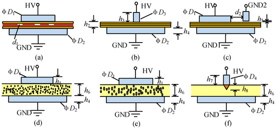
Figure 2.
Artificial PD models. (a) Cavity discharge; (b) Surface discharge; (c) PD due to bad grounding; (d) PD due to floating particles; (e) PD in air bubble dissolved in oil; (f) PD caused by metal protrusions.
In field practices, bad grounding, raised bolts, or multipoint grounding of the iron core inside the transformer, as shown in Figure 3, will lead to floating potential and finally develop into PDs. Thus, a combination of the plate-plate electrodes and rod-plate electrodes is used to simulate such bad grounding induced floating discharges, which is shown in Figure 2c. For models d and e, metal particles (copper filings) and air bubbles are added to the oil and the flow through the electrodes along with the oil flow. In Figure 2f, a pair of needle-plate electrodes is used to simulate metal protrusions caused PD. The geometry size of the electrodes marked in Figure 2 is provided in Table 2.
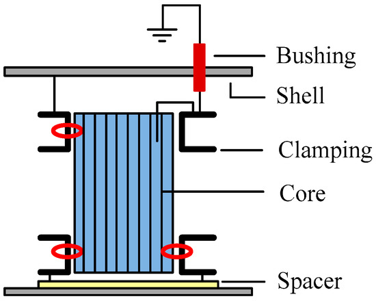
Figure 3.
Grounding sketch of the iron core, the red circles represent the places where bad grounding may take place.

Table 2.
Geometry size of artificial PD models (in mm).
2.1.3. The Measurements
For PD measurement, a digital oscilloscope (TDS 3052C, Tektronix, OR, USA) was adopted. The voltage applied to the test objects was detected and sent to Channel A.
In this paper, the PD signals were measured in two ways: by a high-frequency current transducer (with 0.05 MHz~100 MHz in bandwidth) and a broadband flat-type ultra-high frequency (UHF) sensor (0.3 GHz~1.5 GHz in bandwidth and 50 Ω in input impedance). The high-frequency current transducer signal was sent to the oscilloscope via channel C for PD repetition rate and Qmax calculation. The UHF sensor was pasted on the outer wall of tank 2 (Figure 1) and its signal was collected by channel D of the oscilloscope for later FFT spectrum calculation. PD detection circuit and calibration procedures were implemented according to the IEC standard [29]. All signals recorded by oscilloscope were uploaded to a personal computer online.
2.2. Operating Principle of Test Platform
Initially, the voltage applied to the test models was set at 2 kV and then risen with 0.3 kV/s till the PD level reached 10 pC and meanwhile the corresponding voltage was taken as the PD inception voltage. After that, the voltage amplitude would keep increasing until the PD quantity exceeded 100 pC. To make sure the measured PD quantity comes from continuous and relatively stable PD activity, the voltage applied on the test object should be sustained about 2 min. When the PD amplitude exhibited a downward trend, a previous record can be regarded as the maximum PD quantity Qmax. At the same time, the high-frequency current transducer and the UHF signal were recorded. Finally, the applied voltage can be turned down to zero. Each PD model repeated the same procedure for 10 times with a time interval more than 2 min.
For paper-type PD models (a, b, and c in Figure 2), when the insulating papers/pressboards were immersed in oil and fixed between the electrodes, the oil temperature should be adjusted to a constant value. Note that, before the experiment, the papers/pressboards should be immersed in oil for 72 h to make them completely soaked [30]. The PD parameters were recorded along with the voltage waveform. For oil-type PD models (model d, e, and f in Figure 2), the oil flow speed was set to a constant value during the test.
Compared with other PD models, the test procedures for model e and f were complex. The particles with each size about 0.5 mm~1.0 mm in diameter were added to oil through the sprue on the top side of tank 1 and stirred by a three blades electrical blender. With a pump used, the particles can be mixed in oil and circulated through the electrodes. The same procedures were repeated for model e. To ensure the PDs are induced by air bubbles dissolved in oil, the injected air was separated into numbers of small bubbles by stirring. As the diameter of the air bubble is very small (diameter smaller than 3 mm), it can help to decrease the floating force of the air bubbles, thus provides a way for sustaining them in oil.
3. Measurements and Analysis
During life cycle, the traction substation transformer always withstands intermittent load shocks. As is shown in Figure 4, during neutral section passing, pantograph off-line or braking, the voltage amplitude was almost doubled to the normal level. Voltage waveforms were distorted and harmonics in different orders of high total harmonic distortion were introduced.
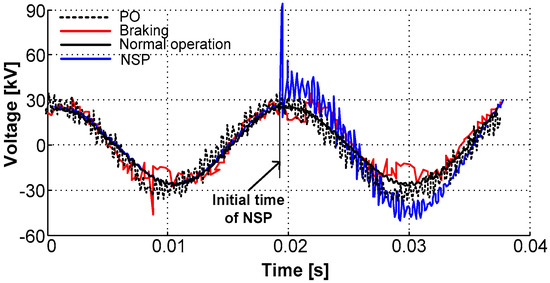
Figure 4.
The voltage measured in the neutral line of LV side of a traction substation transformer.
Figure 5 presents the monitored harmonic distributions in the neutral line of LV side of a traction substation transformer during a high-speed train passing the neutral section. It is clear that the harmonic orders are mainly concentrating on the 3rd, 5th, 7th, 9th, and 50 ± 5th, and a content of 37.03% in total harmonic distortion can even be measured in the current. Even compensations applied, the total harmonic distortion still possesses a higher content about 3~10%, which is much higher to that defined in the standard [31]. Up to now, few studies about the PD properties of traction substation transformers under traction load shocks have been reported. Therefore, the influences of the primary factors induced by the shocks were investigated in this study.
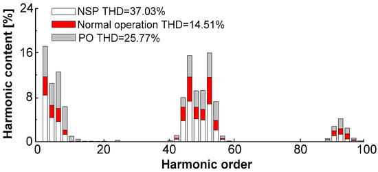
Figure 5.
Measured harmonic distribution during a high-speed train passing the neutral section.
3.1. PD Test under Harmonic AC Voltages
In this study, a function generator is used to generate AC voltage waveform with different total harmonic distortions with certain orders of harmonic. The THD varied from 0.35% (for pure AC voltage waveform) to 32% with a constant step THD = 8%. The harmonic orders are selected according to the on-site measured results (Figure 5), they are the 3rd, 5th, 7th, and the (45 + 2n)th, n = 0, 1 … 5, in this paper. With harmonic orders fixed, the proportion of total harmonic distortion is then adjusted by altering the ratio of the harmonic peak voltage to the fundamental frequency voltage in Equation (1). The tests were conducted under a constant oil temperature Toil = 20 °C.
Figure 6 presents the measured parameters of different PD model obtained from six independent tests. Notably, the PD quantity caused by background noise was calibrated (5.6 pC). In this study, the maximum PD quantity and the PD repetitive rate of each PD model are recorded under 22.5 kV.
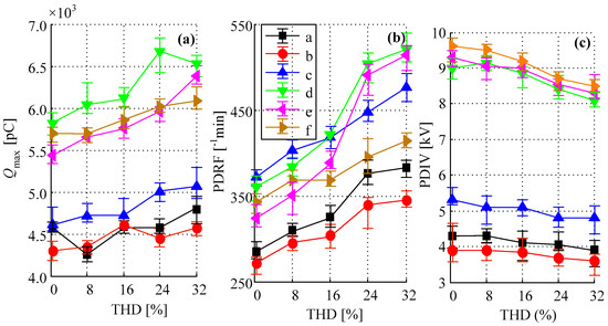
Figure 6.
Measured parameters of six PD models under different THD conditions. (a) The maximum PD quantity; (b) the PD repetitive frequency; and (c) the PD inception voltage.
It is clear from Figure 6a,b that, of all PD models, the PD of air bubbles dissolved in oil (model e) is much easier to be affected, while the surface PD (model b) is not affected too much when THD increases. As the THD increases, the maximum PD quantity and the PD repetitive rate keep increasing while the figure for PD inception voltage exhibits a downward trend. The maximum PD quantity of paper-type PD models is much lower than that of the oil-type PD models, i.e., the Qmax of cavity PD is almost 1100 pC lower than model d. The same trend, as presented in Figure 6c, can be found on the PD inception voltage of these models. Among all, the particle discharge (model d) has the largest increment in Qmax, about 800 pC when the THD increases from 0.35% to 32%. In comparison, the surface PD (model b) owns the lowest variation, only have a 300 pC increase when the THD increases from 0.35% to 32%.
As is illustrated in Figure 6b, the PD repetitive rate of model e has an increment of about 60% when the THD increases from 0.35% to 32%. It is noticeable that the PD repetitive rate of model c is the highest among these models when the THD below 5% and which maintains a higher value than that of the model a, b, and f whatever the THD is. Compared with the oil-type PDs, the decline in PD inception voltage of paper-type PDs is relatively lower, the maximum reduction is about 0.5 kV of model a. As is depicted in Figure 6c, the variation in PD inception voltage of three paper-type PD models is 0.9 kV. Together with Figure 6a–c, it is easy to find that the oil-type PD models have a higher increment in maximum PD quantity Qmax, PD repetitive rate, and PD inception voltage when the THD is higher than 16% compared with paper-type PD models.
Figure 7 shows the UHF signals (left), the corresponding FFT spectrums (middle) and the accumulated spectrum amplitude of PD model a, where the figure number 1, 2, and 3 denote for three different total harmonic distortion scenarios. The FFT spectrum is obtained with a window size of 4096 and a sample rate of 3 GHz. It is clear that the variation in THD has no significant impact on the central frequency of the FFT spectrums, but affects the accumulated spectrum amplitude (Figure 7c). As the THD increases, some pseudo dominant frequency intervals (i.e., D12, D22, D32, etc.) appears and the accumulated amplitude increases.
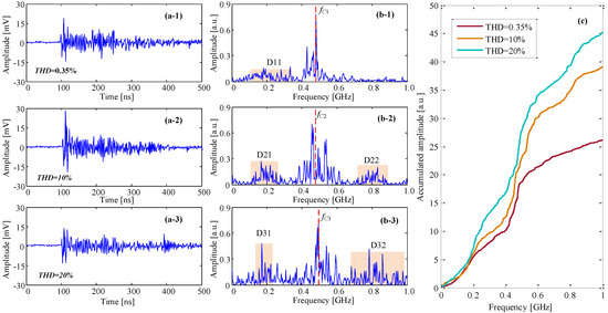
Figure 7.
UHF waveform, FFT spectrum and accumulated spectrum amplitude of PD signals for model a under a mixed AC voltage with different test conditions. (a-1–a-3) the UHF waveforms with different THD content, (b-1–b-3) the FFT spectra of different UHF waveforms, (c) the accumulated spectrum amplitude of different UHF spectrums.
In Figure 7(b-1–b-3), the central frequencies fC of three FFT spectrs under different THDs are 0.48, 0.47 and 0.48 GHz, which almost keep stable as THD increases. As the THD increases, some pseudodominant frequency intervals appear on the FFT spectra. It seems two pseudodominant frequency intervals D21 and D22 appear in Figure 7(b-2) when the THD rises from 0.35% to 10%, and that becomes more apparent in Figure 7(b-3) as the THD increases to 20%. Along with the increase in THD, the accumulated amplitude of the FFT spectrum increases from 26.5 (THD = 0.35%) to 45.2 (THD = 20%).
For further investigation, FFT spectra of each PD model under different THDs are plotted in Figure 8 (with a window size of 4096 and a sample rate of 4.5 GHz, the same configuration used for the figures that will be introduced later). It is clear that, among all PD models, the model d has the largest amplitude, and the central frequency of model b is the easiest to be recognized. The central frequency of each PD model under a low THD (0.35%) is given in Table 3.
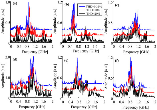
Figure 8.
FFT spectra of different PD models, the subfigure (a–f) refers to model a to model f.

Table 3.
Central frequency of different PD defect models (THD = 0.35%).
When the total harmonic distortion increases, distortion in the voltage waveform will affect the field stress and the levitation voltage. As corona may occur before PD happens, the frequency distributions of FFT spectra transformed by UHF signals are thus affected. With the increase in total harmonic distortion, the central frequencies are still easy to obtain (Table 3) but not easy to recognize by visual inspection as some pseudodominant frequency intervals occur. Thus, the influences of total harmonics distortion containing in the supply voltage should be considered when ultra-high frequency signals are used for PD recognition.
3.2. PD Test under Variable Temperature
Traction substation transformers installed in heavy haul railway substations or high-speed railway substations, always suffer from the short-term over temperatures. Long-term over temperature or short-term high-temperature rise is one of the adverse factors that have momentous effects on the lifespan of the oil/paper insulation.
Figure 9 presents a field measured top oil temperature curve of a traction substation transformer during one day. Actually, the oil temperature always exceeds 100 °C and sometimes even reaches to 130 °C. Thus, in this study, the test temperature was set between 50 °C and 125 °C with a gradient of 15 °C. Configurations of the test are same with that used in Section 3.1. Here, the pure AC voltage (THD = 0.35%, 50 Hz) was applied to the PD models. Recorded PD parameters of six independent tests are shown in Figure 10 and Figure 11.
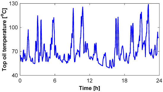
Figure 9.
Field measured oil temperature of traction substation transformer during one day.
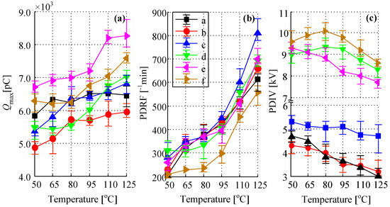
Figure 10.
Measured parameters of six PD models under variable oil temperature. (a) The maximum PD quantity; (b) the PD repetitive rate; and (c) the PD inception voltage.
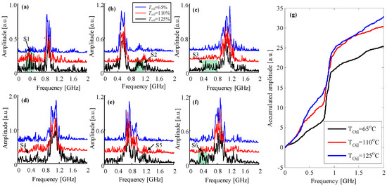
Figure 11.
FFT spectra of different PD models, the subfigure (a–f) refers to model a to model f, (g) refers to the accumulated amplitude of FFT spectrum of model a under different oil temperature.
As shown in Figure 10a, at an initial oil temperature 50 °C, the PD in oil/air bubble (model e) has the highest Qmax while the surface discharge (model b) has the least. This trend varies along with the temperature rise. For model d and f, the Qmax firstly declines when the oil temperature is below 80 °C, but then increases with the temperature rise. For other PD models, the Qmax maintains a rapid increase when the oil temperature rises from 50 °C to 65 °C, but is changed only slightly and almost remains stable when the oil temperature increases from 65 °C to 95 °C. However, when the oil temperature exceeds 95 °C but is below 110 °C, the Qmax increases again and finally stays stable as the oil temperature reaches 125 °C. The same trend goes with the PD repetitive rate of all PD models. In Figure 10b, it is apparent that the PD repetitive rate, of all PD models, almost doubled and even tripled (model a, b and c). The PD repetitive rate increases rapidly when Toil goes from 50 °C to 65 °C, but slowly when Toil varies between 65 °C and 95 °C. After that, the PD repetitive rate drastically increases. Among all PD models, the model c has the largest increment, which increases from initial 280 times per minute to final 810 times per minute.
From Figure 10c, it is easy to find the PD inception voltage of oil-type PD models is much higher than that of paper-type PD models. The PD inception voltage of the model a, b, and e declines when Toil increases, but is constant for model c. It is interesting that the PD inception voltage of model d and f increases when Toil rises from 50 °C to 85 °C and reaches their peak values, then shows a downward trend when Toil exceeds 85 °C. This mainly because the traces amounts of water dissolved in oil decrease due to evaporation, and the concentration of dissolved gas in oil increases decline due to gas solubility when Toil increases [32]. At a low oil temperature (below 65 °C), the surface PD (model b) has the lowest PD inception voltage, but it reaches the same level as the cavity discharge (model a) when Toil exceeds 80 °C.
It is obvious from Figure 11 that the central frequencies of the spectra almost remain stable and are easy to recognize when the oil temperature is below 80 °C. However, some pseudodominant frequency intervals become apparent when the oil temperature reaches to 110 °C (S1 to S6 in Figure 11) and the accumulated amplitude of the FFT spectrum becomes higher (e.g., the accumulated amplitude of model a shown in Figure 11g).When the temperature increases to 120 °C, this phenomenon is more apparent. The central frequency, however, is still clear enough for identification. Compared with the FFT spectrum derived under variable total harmonics distortion in Section 3.1, the temperature has no significant impact on the central frequency except for some small pseudodominant frequency intervals and a slight increase in the accumulated amplitude of the FFT spectrum.
3.3. PD Test under Square Voltage Pulse Superimposed AC Voltage
During the process of pantograph lifting/separating, braking or neutral section passing of a train, the voltage measured from the neutral line of the LV side of the traction substation transformer, as depicted in Figure 4, is doubled compared to the rating. To investigate the PD behavior under such voltage waveform conditions, the square voltage impulse (50 Hz) with 0.35 ms in width and 3.6 kV in amplitude was produced and superimposed on the 50 Hz AC voltage. Figure 12 presents a typical transient overvoltage waveform of traction substation transformer during neutral section passing and a square impulse voltage waveform generated by the high voltage impulse generator. The generation process of the square impulse voltage has been introduced in Section 2.
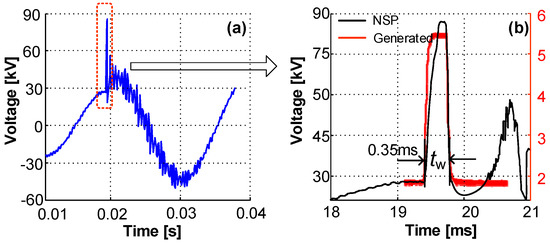
Figure 12.
Square voltage impulse superimposed on 50 Hz AC voltage. (a) Field measured voltage from the low-voltage side of the traction substation transformer during neutral section passing; (b) the generated voltage impulse and partially magnified impulse of (a).
By importing the measured signal using high-frequency current transducer signal into MATLAB, the PD repetitive rate and the maximum PD quantity can be obtained. Here, considering the initial delay of the PD pulse current is smaller and the PD pulse current amplitude is larger than the capacitive displacement current, and the PD pulse width is substantially constant (around 0.5 µs) than the capacitive displacement current (usually larger than 1 µs), the capacitive displacement currents can be removed from the test high frequency current signal. Thus, the influence of capacitive displacement current on PD inception voltage can be reduced.
As is pointed out in [33], the angle of the cycle at which the impulse is applied has a significant impact on the PD inception voltage and times of PD. Therefore, in this paper, the positive square impulse waveform was added to the AC waveform at a fixed power phase of 90 degrees to eliminate such an impact.
Figure 13 presents the test results of PD level, PD repetitive rate, and PD inception voltage of six PD models under two distinct voltage waveforms of six independent tests. It is apparent from Figure 13a that, of all PD models, the Qmax under a positive square impulse superposed AC voltage waveform is much higher compared with that recorded under a pure sinusoidal AC waveform. The PD model f has the highest maximum PD quantity while model b has the lowest. With a superposed square impulse voltage, however, the PD model that has the highest Qmax is no longer model f, but model e. Moreover, the difference of Qmax of each PD model become smaller compared that with only pure AC voltage applied. As is depicted in Figure 13b, the PD repetitive rate of all PD models obviously increases when the square impulse is applied. Among all, the model d has the largest increment. It is clear in Figure 13c that the PD inception voltage almost of all models (except model a) is greatly reduced when the square impulse voltage is superimposed (half of the original).
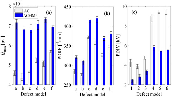
Figure 13.
PD parameters of six PD models under two distinct voltage waveforms. (a) The maximum PD quantity, (b) the PD repetitive voltage, and (c) the PD inception voltage.
The equivalent circuits and PD schematic diagram of cavity discharge (model a) and PD in air bubble dissolved in oil (model e), presented in Figure 14 and Figure 15, help illustrate how square impulses influence their PD parameters. The cavity or air bubble (the dotted ellipse, denoted as C/A in the left of Figure 14), can be modeled using Cc in parallel with an air gap that acts as a controlled switch with the voltage across the C/A. The capacitor Cb1 and Cb2 represent the capacitance of the part of insulation in series with C/A. Ca1 and Ca2 stand for the capacitance of the majority of the insulation parallel to C/A [32]. For simplicity, denoting Cb as the series capacitance of Cb1 and Cb2, Ca as the parallel capacitance of Ca1 and Ca2, the potential drop on Cc as Vc, and the voltage applied to terminals A and B as Va. All capacitors can be charged just by increasing Va. As the capacitor Cc is charging, the voltage across it would increase gradually.

Figure 14.
PD model (left) and its equivalent circuit (right) of PD defect model a or/and e.
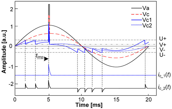
Figure 15.
Repetition of PD pulses in a cavity or an air bubble under a combined waveform with square impulse superimposed on AC voltage.
- (1)
- When Va bellows the PD inception voltage of the PD models that only with pure AC voltage applied, the potential drop Vc1 would not reach to a breakdown voltage U+ until a square impulse voltage was superimposed on the waveform at a phase angle of 90 degrees. That is why the PD inception voltage decreases dramatically (plotted in Figure 13c) under a combined voltage waveform. The capacitor Cc would be discharged and the potential would decrease to the voltage V+ that needed for extinguishing the PD pulse. The PD current ic (t) would last for a very short time, which can be described using a typical PD circuit shown in the dotted orthogon in Figure 14. In this case, only one discharge impulse can be recorded, which is plotted in dotted blue line in Figure 15. However, as the potential drop on Cc is much higher than it needed for discharge, the amplitude of ic_1(t) would also be much higher.
- (2)
- As Va increases to the same level or exceeds the PD inception voltage of the PD models only with pure AC voltage applied, two discharge impulses a and b would occur before the square voltage impulse applied. The potential drop Vc2 would reach to a breakdown voltage U+ suddenly at time timp, and this would result in a big discharge impulse. After that, another five discharge impulses would occur with only pure AC voltage applied. In this case, the PD current is depicted as ic_2(t). Together with the first case, it is easy to find that the number of impulses as well as the amplitude of discharge will increase once a square impulse applied, and that is why the Qmax and PD repetitive rate increase greatly in Figure 13a,b.
Figure 16 presents the FFT spectra before and after the square impulse voltage is applied. The corresponding central frequencies of different PD defect models are given in Table 4. It is clear that the central frequency of each PD model almost remains stable except for model d. As has been proved by Sarathi et al. [34], the central frequency of measured ultra-high frequency PD signals from surface discharge would not change with the applied AC voltage, and the discharge mechanism is the main factor that has an impact on the frequency distribution. Moreover, it was also proved that the frequency spectrum of PD signals caused by suspended air bubbles in oil is different from that caused by metal particles [35]. Under a pure AC voltage (before square impulse voltage is superimposed), the drag force of the oil has a block effect on the displacement of the particles from towards one electrode. The PDs take place under such scenario is more or less like a kind of oil discharge. However, after a square impulse voltage is superimposed, the amplitude of the electrical force will exceed the combination of the gravitation and drag force. This makes the particles move to electrode more easily than under pure AC voltage. Such effect results in localized PD at the electrode surface, which behaves like a surface discharge in oil. Each of a localized discharge, therefore, is a UHF signal. The FFT results presented in Figure 16d have a good agreement with that.
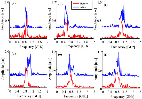
Figure 16.
FFT spectra of different PD defect models with Toil = 23 °C and THD = 0.35%, the subfigure (a–f) refers to model a to model f.

Table 4.
Central frequency of different PD models before/after the square voltage impulse superimposed.
However, it was found that the central frequency of model d (Figure 16d) has a slight shift towards the higher frequency band when the square impulse was superimposed. As was also proved by Sarathi et al. [36], when the local electrical field is higher than the inception voltage, the central frequency of UHF signal would shift from 1 GHz to 2 GHz, which confirms the results obtained in this paper. It is apparent from Table 4 that, for different PD models, the dominant frequency of each model is different, except model a, d, and f. However, as the amplitude of this three signal are different from each other (0.6 for mode a, 1.0 for model d and 0.5 for model f), it can be used as a complementary parameter for PD pattern recognition.
3.4. Discussions
In the actual field, the influences of traction load shocks always exist. Under such circumstances, the PD parameters recorded from on-site condition always exhibit with high dispersity, thus making it difficult for PD pattern recognition of those traction substation transformers in service.
An effective way for PD recognition is to make utilization of all the data that can be acquired both online and offline. Actually, the PD parameters, like the maximum PD quantity, the PD repetitive rate, the phase distribution, etc., can be obtained easily. Together the specific scenarios under which the PD parameters are recorded, (i.e., the total harmonics distortion, the oil temperature and the voltage waveform) different fingerprints can be formatted and thus help to identify different types of PD faults. Among the PD parameters investigated in this paper, the central frequency (or dominant frequency) and the amplitude of FFT spectrum can be taken as the principal features in PD recognition. Additionally, it can be easy to get from Figure 6 and Figure 10 that the maximum PD quantity Qmax is also helpful for distinguishing the PD from an oil-type to a paper-type.
4. Conclusions
In this paper, the total harmonics distortions, the temperature rise, and the transient voltage impulse induced by traction load shocks were considered as three principal factors that influence the PD characteristics of traction substation transformers. Laboratory PD tests were conducted with six artificial PD models. The PD feature parameters, including the maximum PD quantity, the PD repetitive rate, the PD inception voltage and the central frequency of the FFT spectrum transformed from UHF signal were recorded.
From the tests, it was found that the feature parameters of PD were closely related with THD containing in the applied AC voltage, the temperature rise of the oil and the transient voltage impulse. Some pseudodominant frequency intervals found in the FFT spectra of different PD models and the increase in the accumulated amplitude of FFT spectrum can mainly be attributed to the high proportion of THD. The central frequency can help to distinguish different PD models while the accumulated amplitude of FFT spectrum of a certain PD model can reflect the effect of THD or oil temperature variation. The higher the THD, the more apparent the pseudodominant frequency intervals would be, and the higher the accumulated amplitude of the FFT spectrum. The maximum PD quantity and the PD repetitive rate were favorable to be enlarged due to temperature rise, especially for oil-type PDs, while the decline in PD inception voltage can be attributed to the occurrence of transient voltage impulses. Besides, it was also observed that the PD inception voltage of oil-type PDs (PD due to floating particles and metal protrusions), show a distinctive trend, which would increase firstly when the temperature was below 80 °C, and then kept decreasing as the temperature rises.
The study presented in this paper lays a foundation for future PD recognition of traction substation transformers. In the future, the PD activity in portions of the supply voltage with large dV/dt changes and the statistical features of PRPD plots will also be considered for further study. In the actual field, the PD characteristics may be influenced by various adverse factors, especially the three studied in this paper. This would result in a misrecognition of PD patterns using the recorded signals. However, if voltage waveform details (i.e., travelling waveform parameters, harmonics, load flow, etc.) can be acquired, and the oil temperature can be obtained, together with the FFT spectra of ultra-high frequency signals and the structure of the transformer under investigation, it is possible to recognize PDs by means of field tests and measurements.
Acknowledgments
This work was also supported by the National Natural Science Foundation of China (NSFC, Nos. 51325704 and U1234202), and the Opening Project of the State-Key Laboratory of Traction Power under Grant 2017TPL_Z03.
Author Contributions
In this paper, Guoqiang Gao, Shuaibing Li, Bo Gao and Guangning Wu conceived and designed the experiments; Haojie Yin and Guangcai Hu performed the experiments; Shuaibing Li and Wenfu Wei analyzed the data and wrote the paper.
Conflicts of Interest
The authors declare no conflict of interest. The founding sponsors had no role in the design of the study; in the collection, analyses, or interpretation of data; in the writing of the manuscript, and in the decision to publish the results.
References
- Andreev, V.V.; Grechishnikov, V.A.; Privezentsev, N.N.; Shevlyugin, M.V. Calculation of a relative actualized transformer power of a traction substation on insulation aging. Russ. Electr. Eng. 2011, 82, 441–444. [Google Scholar] [CrossRef]
- Lao, K.W.; Wong, M.C.; Wong, C.K.; Lam, C.S. A systematic approach to hybrid railway power conditioner design with harmonic compensation for high-speed railway. IEEE Trans. Ind. Electron. 2015, 62, 930–942. [Google Scholar] [CrossRef]
- Zhuo, S.; Jiang, X.; Zhu, D.; Zhang, G. A novel active power quality compensator topology for electrified railway. IEEE Trans. Power Electron. 2004, 19, 1036–1042. [Google Scholar] [CrossRef]
- Zhou, L.; Wu, G.; Yu, J.; Zhang, X. Thermal overshoot analysis for hot-spot temperature rise of transformer. IEEE Trans. Dielectr. Electr. Insul. 2007, 14, 1316–1322. [Google Scholar] [CrossRef]
- Liu, Y.; Wu, G.; Hua, H.; Wang, L. Research for the effects of high-speed electrified railway traction load on power quality. In Proceedings of the 4th International Conference on Electric Utility Deregulation and Restructuring and Power Technologies, Weihai, China, 6–9 July 2011; IEEE: Piscataway, NJ, USA, 2011. [Google Scholar]
- Cheng, F.; Sun, Y.; Ma, W. Research on the over-voltage of 220kV power system caused by traction transformer’s commissioning. In Proceedings of the 9th International Conference on Electronic Measurement & Instruments, Beijing, China, 16–19 August 2009; IEEE: Piscataway, NJ, USA, 2009. [Google Scholar]
- International Electrotechnical Commission. Railway Applications-Traction Transformers and Inductors on Board Rolling Stock, IEC Standard 60310–2004; International Electrotechnical Commission: Geneva, Switzerland, 2004. [Google Scholar]
- 220 Single Phase Traction Transformer; Machinery Industry Standard of the People’s Republic of China; National Development and Reform Commission of the P.R. China: Beijing, China, 2007; JB/T 10776-2007. (In Chinese)
- Vv Connection Traction Transformer; Ministry of Industry and Information Technology Standard of the People’s Republic of China; Ministry of Industry and Information Technology of the P.R. China: Beijing, China, 2013; JB/T 11328-2013. (In Chinese)
- Pompili, M.; Bartnikas, R. On partial discharge measurement in dielectric liquids. IEEE Trans. Dielectr. Electr. Insul. 2012, 19, 1476–1481. [Google Scholar] [CrossRef]
- Pompili, M. Partial discharge development and detection in dielectric liquid. IEEE Trans. Dielectr. Electr. Insul. 2009, 16, 1648–1654. [Google Scholar] [CrossRef]
- Pompili, M.; Mazzetti, C.; Bartnikas, R. Comparative Partial discharge impulse burst characteristics of transformer type natural and synthetic ester fluids and mineral oils. IEEE Trans. Dielectr. Electr. Insul. 2009, 16, 1511–1518. [Google Scholar] [CrossRef]
- Suresh, S.D.R.; Savadamuthu, U. Cluster classification of partial discharges in oil-impregnated paper insulation. Adv. Electr. Comput. Eng. 2010, 10, 90–93. [Google Scholar] [CrossRef]
- Wang, K.; Li, J.; Zhang, S.; Gao, F. A new image-oriented feature extraction method for partial discharges. IEEE Trans. Dielectr. Electr. Insul. 2015, 22, 1015–1024. [Google Scholar] [CrossRef]
- Chen, W.; Chen, X.; Peng, S.; Li, J. Canonical correlation between partial discharges and gas formation in transformer oil/paper insulation. Energies 2012, 5, 1081–1097. [Google Scholar] [CrossRef]
- Chan, J.; Ma, H.; Saha, T.K. Automatic blind equalization and thresholding for PD measurement in Power Transformer. IEEE Trans. Power Deliv. 2014, 29, 1927–1938. [Google Scholar] [CrossRef]
- Niasar, M.G.; Taylor, N.; Janus, P.; Wang, X. Partial discharges in a cavity embedded in oil-impregnated paper: Effect of electrical and thermal aging. IEEE Trans. Dielectr. Electr. Insul. 2015, 22, 1071–1079. [Google Scholar] [CrossRef]
- Kiiza, R.C.; Niasar, M.G.; Nikjoo, R.; Wang, X. Change in partial discharge activity as related to degradation level in oil-impregnated paper insulation: Effect of high voltage impulses. IEEE Trans. Dielectr. Electr. Insul. 2014, 21, 1243–1250. [Google Scholar] [CrossRef]
- Liao, R.; Yang, L.; Li, J.; Grzybowski, S. Aging condition assessment of transformer oil-paper insulation model based on partial discharge analysis. IEEE Trans. Dielectr. Electr. Insul. 2011, 18, 303–311. [Google Scholar] [CrossRef]
- Li, J.; Si, W.; Yao, X.; Li, Y. Measurement and simulation of partial discharge in oil impregnated pressboard with an electrical aging process. Meas. Sci. Technol. 2009, 20, 251–252. [Google Scholar] [CrossRef]
- Sun, Z.; Gu, C.; Zhao, X.; Li, Y. Partial discharge activity in oil—Paper insulated system under DC superimposed AC and harmonic voltage. Electr. Rev. 2011, 87, 199–201. [Google Scholar]
- Tsuchie, M.; Kozako, M.; Hikita, M.; Sasaki, E. Modeling of early stage PD and overheating degradation of paper-oil insulation. IEEE Trans. Dielectr. Electr. Insul. 2014, 21, 1342–1349. [Google Scholar] [CrossRef]
- Florkowski, M.; Florkowska, B.; Furgal, J.; Zydron, P. Impact of high voltage harmonics on interpretation of PD patterns. IEEE Trans. Dielectr. Electr. Insul. 2014, 21, 2383–2393. [Google Scholar] [CrossRef]
- Sha, Y.; Zhou, Y.; Zhang, L.; Huang, M. Measurement and simulation of PD in oil-paper insulation under the combined AC-DC voltage. J. Electrost. 2013, 21, 2009–2016. [Google Scholar] [CrossRef]
- Gao, B.; Wu, G.; Tong, L.; Lin, T. Novel insulation aging test system based on continuous high voltage square impulses for inverter-fed traction motors. Chin. J. Sci. Instrum. 2008, 29, 43–48. [Google Scholar]
- Tang, J.; Zhou, J.; Zhang, X.; Liu, F. A transformer partial discharge measurement system based on fluorescent fiber. Energies 2012, 5, 1490–1502. [Google Scholar] [CrossRef]
- Sarathi, R.; Merin Sheema, I.P.; Sundara Rajan, J.; Danikas, M.G. Influence of harmonic AC voltage on surface discharge formation in transformer insulation. IEEE Trans. Dielectr. Electr. Insul. 2014, 21, 2383–2393. [Google Scholar] [CrossRef]
- Sarathi, R.; Archana, M. Investigation of partial discharge activity by a conducting particle in transformer oil under harmonic AC Voltages adopting UHF technique. IEEE Trans. Dielectr. Electr. Insul. 2014, 19, 1514–1520. [Google Scholar] [CrossRef]
- International Electrotechnical Commission: High-Voltage Test Techniques—Partial Discharge Measurements, IEC Standard 60270; International Electrotechnical Commission: Geneva, Switzerland, 2000.
- Preventive Test Code for Electric Power Equipment; Electric Power Industry Standard of People’s Republic of China; Ministry of Power Industry of the PR. China: Beijing, China, 2005; DL/T 596-2005. (In Chinese)
- Quality of Electric Energy Supply—Harmonics in Public Networks; Standard of the People’s Republic of China; General Administration of Quality Supervision, Inspection and Quarantine of the P.R. China: Beijing, China, 2009; GB/T 14549-2009. (In Chinese)
- Niasar, M.G. Partial Discharge Signatures of Defects in Insulation Systems Consisting of Oil and Oil-impregnated Paper. Ph.D. Thesis, Royal Institute of Technology, Stockholm, Sweden, 2012. [Google Scholar]
- Densley, R.J. Partial discharges in electrical insulation under combined alternating and impulse stresses. IEEE Trans. Electr. Insul. 1970, 4, 96–103. [Google Scholar] [CrossRef]
- Sarathi, R.I.; Merin Sheema, P.; Sundara Rajan, J. Understanding surface discharge activity in copper sulphide diffused oil impregnated pressboard under AC voltage. IEEE Trans. Electr. Insul. 2014, 26, 674–682. [Google Scholar] [CrossRef]
- Tang, J.; Zhu, L.; Ma, S. Characteristics of suspended and mobile microbubbles partial discharge in insulation oil. High Volt. Eng. 2010, 36, 1341–1346. (In Chinese) [Google Scholar]
- Sarathi, R.; Giridhar, A.V.; Mani, A.; Sethupathi, K. Investigation of partial discharge activity of conducting particles in liquid nitrogen under DC voltages using UHF technique. IEEE Trans. Electr. Insul. 2008, 15, 655–662. [Google Scholar] [CrossRef]
© 2017 by the authors. Licensee MDPI, Basel, Switzerland. This article is an open access article distributed under the terms and conditions of the Creative Commons Attribution (CC BY) license (http://creativecommons.org/licenses/by/4.0/).