1. Introduction
With the development of the technology, the embedded wireless sensors and portable microelectronics devices are widely used in industry, agriculture, medicine, and so on. Energy supply is a critical challenge during the practical applications. Capturing the ambient energy, known as energy harvesting provides a clean, renewable, and uninterrupted solution to power the low power-consuming devices. The common energy sources in the ambient environment include solar, wind, thermal, vibration, and radiation energy. Among them, the vibration energy is widely distributed, and possesses high energy density. Generally, the transduction mechanisms of vibration energy harvesting can be divided into piezoelectric [
1], electromagnetic [
2], electrostatic [
3], and magnetoelectric [
4]. Due to the high electromechanical coupling coefficients, simple processing, and no external power supply, piezoelectric energy harvesting is the one of the most reported transduction mechanism. As the power supply of the implantable and portable microelectronic devices, compact size is the demand for the energy harvesters. However, most of the micro-level piezoelectric energy harvesters (PEHs) operate at resonant frequency of 100 Hz or higher [
5,
6,
7]. As a result, resonant vibration energy harvesters suffer from dramatically reduced output power in the low frequency range (less than 30 Hz). In recent years, a great deal of research has been done to improve the generating performance and enhance the environmental adaptability of the PEHs in a low-frequency environment.
Mechanical frequency up-conversion technology was one typical approach proposed for the low frequency application, in which the low-frequency ambient vibration can be converted to the high-frequency vibration of micro energy harvester. Umeda et al. [
8] firstly applied the impact of a steel ball on the piezoelectric membrane for frequency up-converting energy harvesting. Two-stage energy harvesting concept was proposed by Rastegar et al. [
9]. As the first stage, low-frequency oscillation system intermittently transfers the mechanical energy to the secondary stage system with significantly higher natural frequency by interaction contact. Then, the secondary system converts the mechanical energy to electric energy. After the contact, the generating element vibrates with its own high resonant frequency. As a result, the mechanical frequency is up-converted. Based on this concept, related research on frequency up-converting piezoelectric energy harvester (FUCPEH) has been widely conducted. The interaction contact can be further divided into two types. One is mechanical impact [
10,
11,
12], and the other is mechanical plucking [
13,
14,
15,
16]. In the above-mentioned designs, the low-frequency oscillator is only used to trigger the high frequency vibration of the generating element. The kinetic energy of the driving element is only harvested by the generating element. Liu et al. [
17] replaced the driving element with a low-frequency piezoelectric beam, which not only generates electric power, but also introduce high frequency oscillation of the other piezoelectric generating beam. Vijayan et al. [
18] studied the dynamic characteristics of two coupled impacting piezoelectric beams. It was demonstrated that the power generated by the coupled system is sensitive to the thickness ratio of the beams and the clearance. Edwards et al. [
19] collected the kinetic energy of the driving beam by the electromagnetic induction and presented a frequency up-converting hybrid energy harvester (FUCHEH).
In the literature mentioned above, most of theoretical models ignored the influence of the electromechanical coupling term on the equivalent stiffness of the system. The electrical damping induced by the load resistance was considered to be constant and independent of the excitation frequency. Certainly, an accurate theoretical model of the frequency up-converting vibration energy harvester is required for optimization design. In addition, the time-domain responses were analyzed generally, whereas the frequency-domain analysis has almost never been reported. As a result, the contribution of excitation frequencies to the output power is not clear.
In this paper, we report an impact-based FUCHEH, using piezoelectric and electromagnetic conversion mechanisms. The electromechanical coupling model is established in
Section 2 and
Section 3 simulates and analyzes the displacement, velocity, and open-circuit voltages responses of piezoelectric and magnetic oscillators.
Section 4 presents the prototype and an experimental testing system. The generating characteristics of the FUCHEH are measured and discussed.
3. Numerical Simulation
Based on the theoretical model of the FUCHEH, numerical simulation was performed to research the displacement, velocity, and voltage responses by using the ordinary differential equation solver ode45 in MATLAB
® (R2012b, MathWorks Inc.: Natick, MA, USA). For the sake of distinction, the substrate of piezoelectric beam was labeled as substrate A, while that of the magnetic oscillator was substrate B. Both mechanical damping ratios of PEH and EMEH parts were set to 0.02. The initial separation distance at static state was set to 2.4 mm. A harmonic excitation was applied to the FUCHEH with the acceleration amplitude of 1 m/s
2. The geometric and material parameters are given in
Table 1, based on the prototype fabricated.
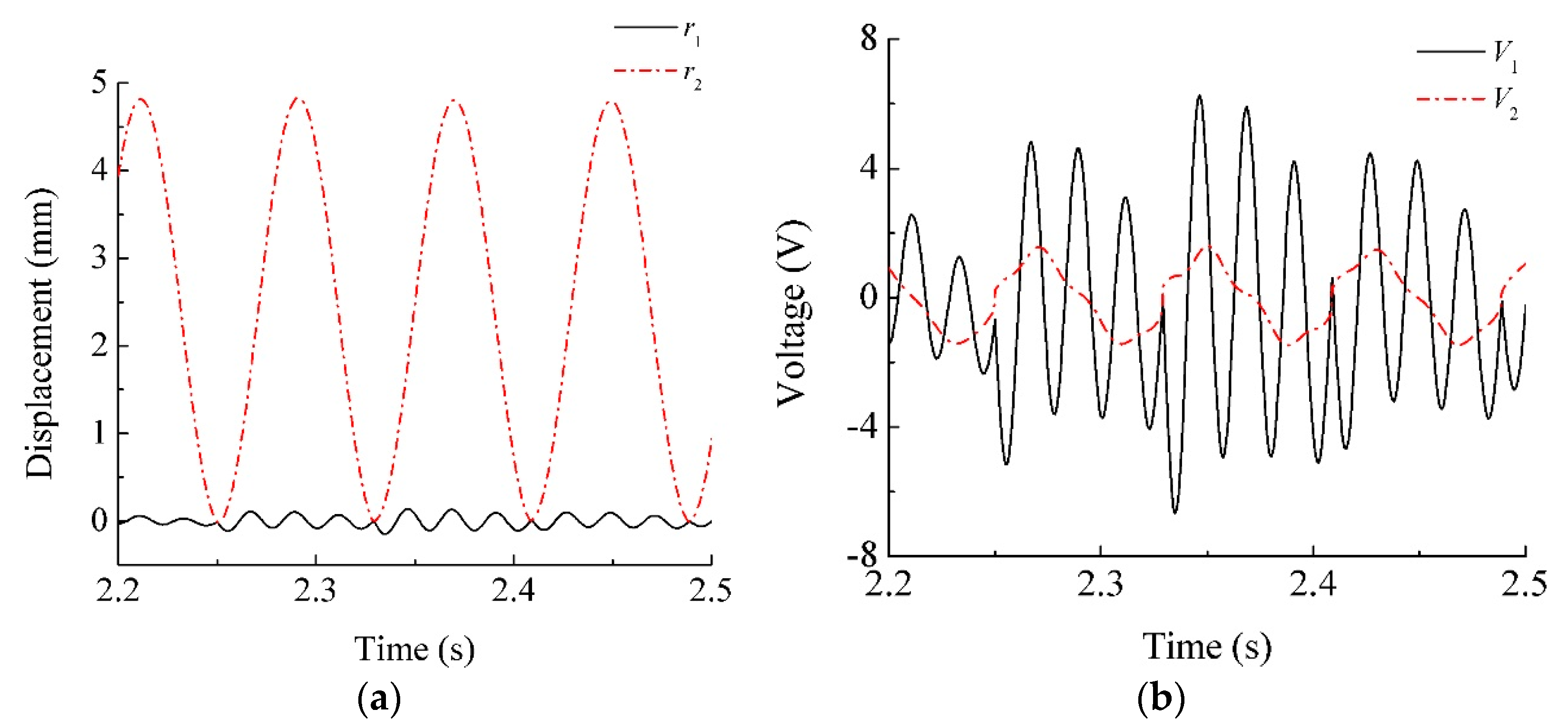
Figure 4 shows the simulated time-domain responses of the piezoelectric and magnetic oscillators that are driven by base excitation. The trends were identical to what we described before. Both load resistances connected to piezoceramic patches and induction coil are assumed to be 10
9 Ω. As a result, the numerical simulation is considered to be conducted under the open-circuit condition. The theoretical natural frequencies of the piezoelectric and magnetic oscillators are about 42.3 Hz and 12.6 Hz, respectively. Therefore, the excitation frequency is set to 12.6 Hz. In
Figure 4a, it can be seen that the displacement of the magnetic oscillator is similar to the sinusoidal curve. The amplitude slightly changes during the oscillation. However, the displacement of the piezoelectric oscillator abruptly rises as the collision occurs. At this moment, two oscillators get in contact with each other and part of the kinetic energy harvested by the magnetic oscillator is transferred to the piezoelectric oscillator through impact, resulting in a rise of its displacement. Meanwhile, the velocities of two oscillators are discontinuous and are assigned new values. After the separation, the piezoelectric oscillator vibrates independently at high frequency and its displacement gradually decays until the next impact occurs. So far, the low-frequency excitation is up-converted.
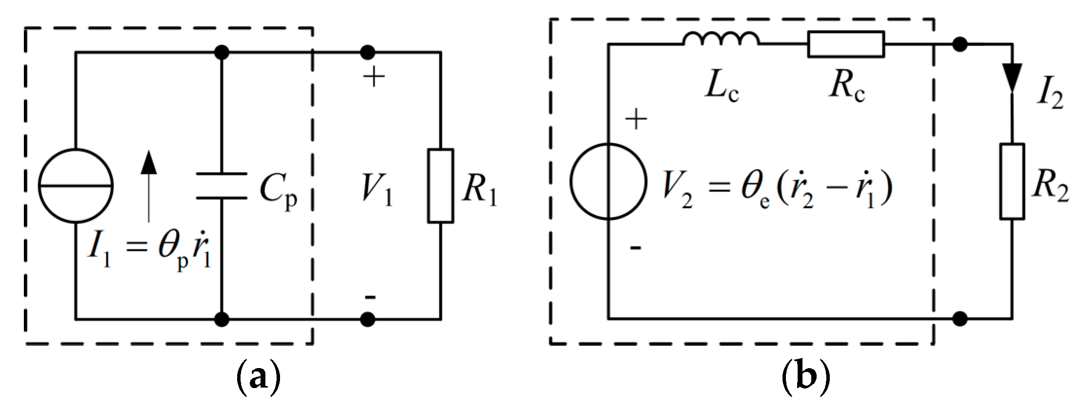
Concomitantly, there are discrete spikes in the open-circuit voltage waveform generated from the PEH element (
V1) when collision occurs and then exponential decay, as shown in
Figure 4b. Obviously, they are triggered by the impact, which is coinciding with the displacement response. The decay rate is not only determined by the mechanical damping, but also the electromagnetic damping. There is also a sudden change for the induced voltage
V2 in the coil as impacting. It jumps from negative value to positive one abruptly. After the collision, its trajectory is similar to the sinusoidal curve.
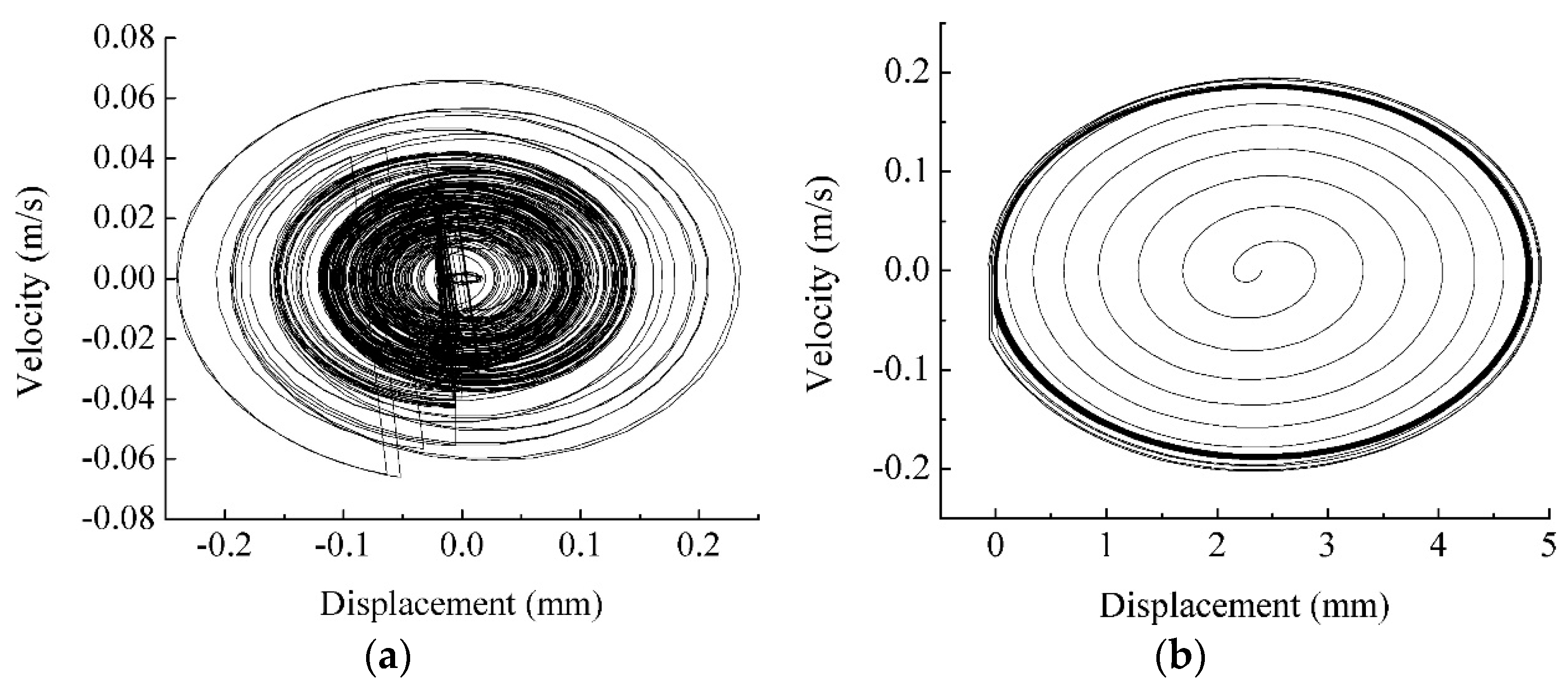
Figure 5a,b show the phase portraits of the piezoelectric and magnetic oscillators, respectively. Obviously, each collision is accompanied by a velocity jump up for the piezoelectric oscillator and a velocity jump down for the magnetic oscillator. After the impact, the piezoelectric oscillator experiences attenuations of displacement and velocity until the moment that the next collision occurs. There is no obvious change for the phase trajectory of magnetic oscillator, which is due to the large initial separation distance between two oscillators.
4. Experiment and Discussion
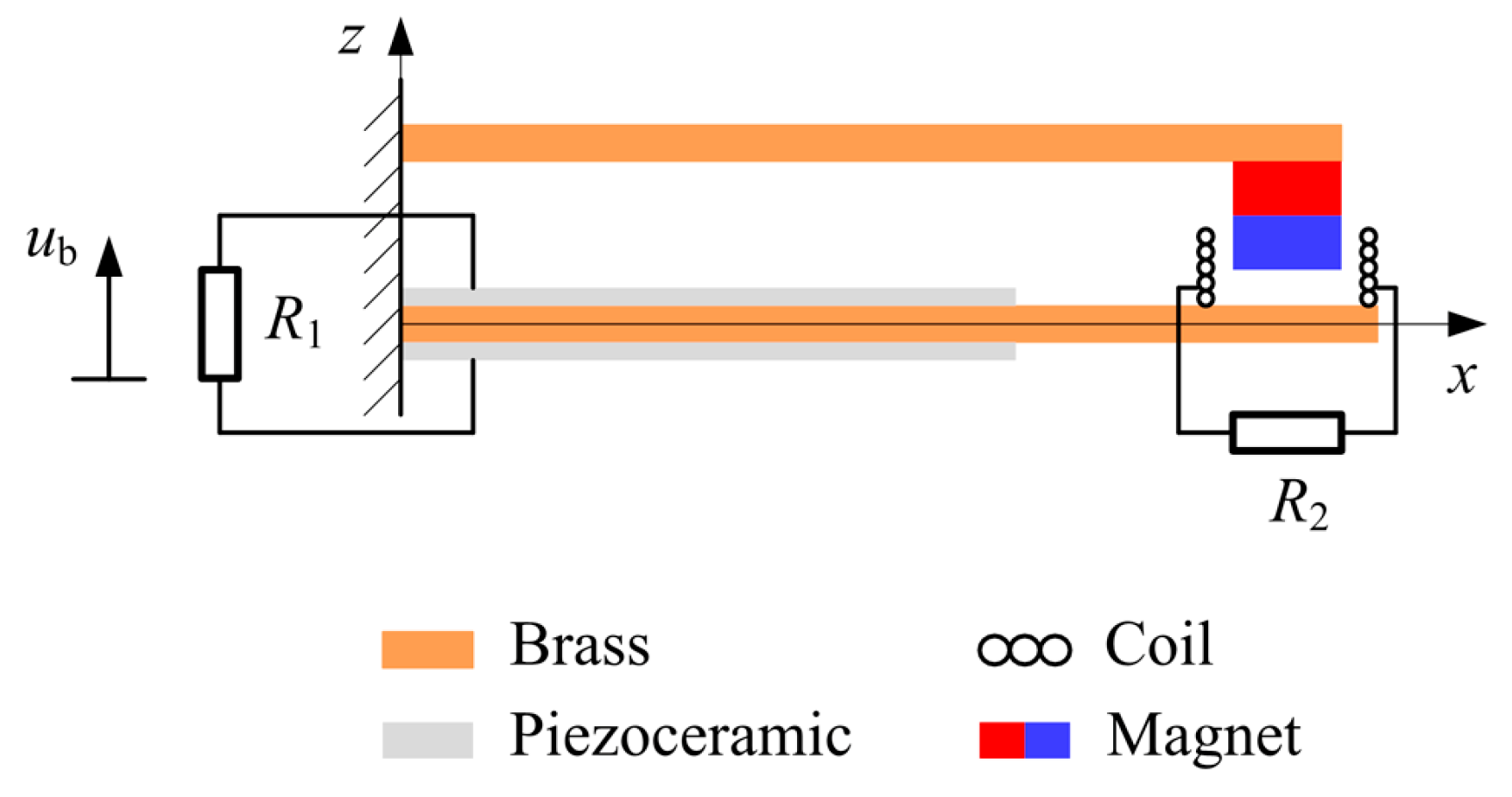
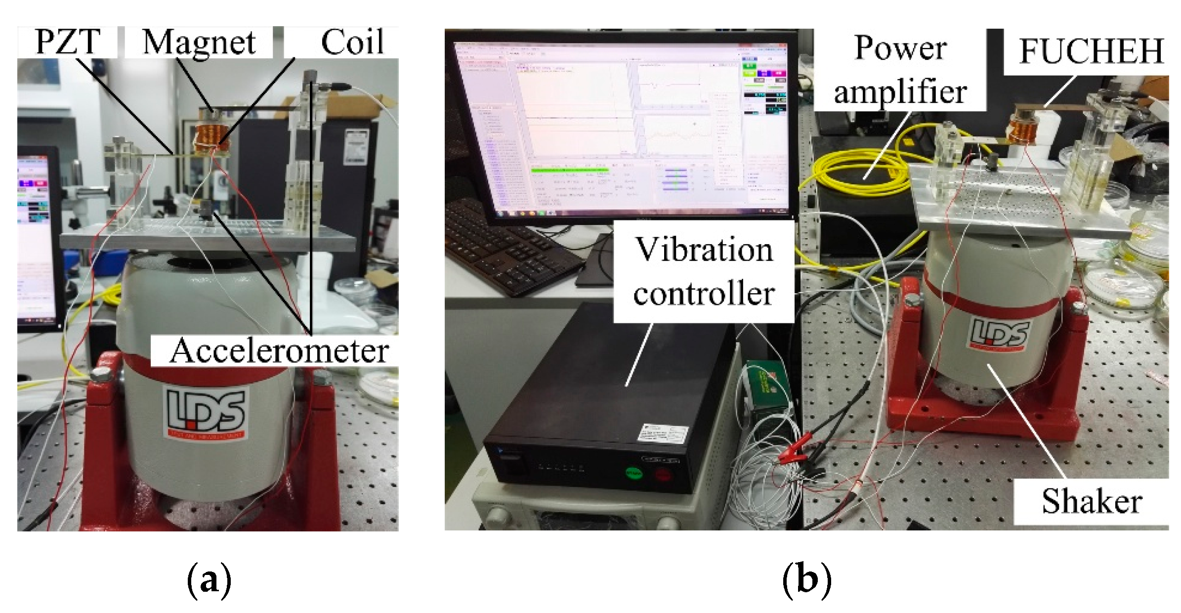
In order to validate the feasibility of the FUCHEH, a meso-scale prototype was fabricated, as shown in
Figure 6a. It consists of a bimorph piezoelectric cantilever beam, a cantilevered driving beam with magnetic proof mass (NdFeB N35), and an induction coil. The substrate A and substrate B are, respectively, made of brass and phosphor bronze. The piezoceramic is lead zirconate titanate (PZT-5H). The geometric and material parameters are summarized in
Table 1. The FUCHEH prototype is clamped to an electromagnetic shaker (LDS V406). The excitation signal is generated by the vibration controller (Spider 81B) and amplified by a power amplifier (LDS PA100E). The excitation acceleration is measured by an accelerometer (PCB 352C33), and is then controlled and monitored by the vibration controller. Finally, all of the voltages that are generated from PEH and EMEH subsystems are input into the vibration controller and recorded.
Figure 6b shows the experimental system for the FUCHEH.
The measured resonant frequencies of piezoelectric and magnetic oscillators, respectively, were 40.5 Hz and 12.8 Hz, which are close to the theoretical value. Therefore, the excitation frequency was set to 13 Hz, so as to capture maximum low-frequency vibration energy. A harmonic excitation acceleration was applied to the FUCHEH with the amplitude of 1 m/s2. The separation distance was set to 2.4 mm. By using the logarithmic decrement method, the mechanical damping ratios of piezoelectric and magnetic oscillators are measured to be 0.02 and 0.015, respectively.
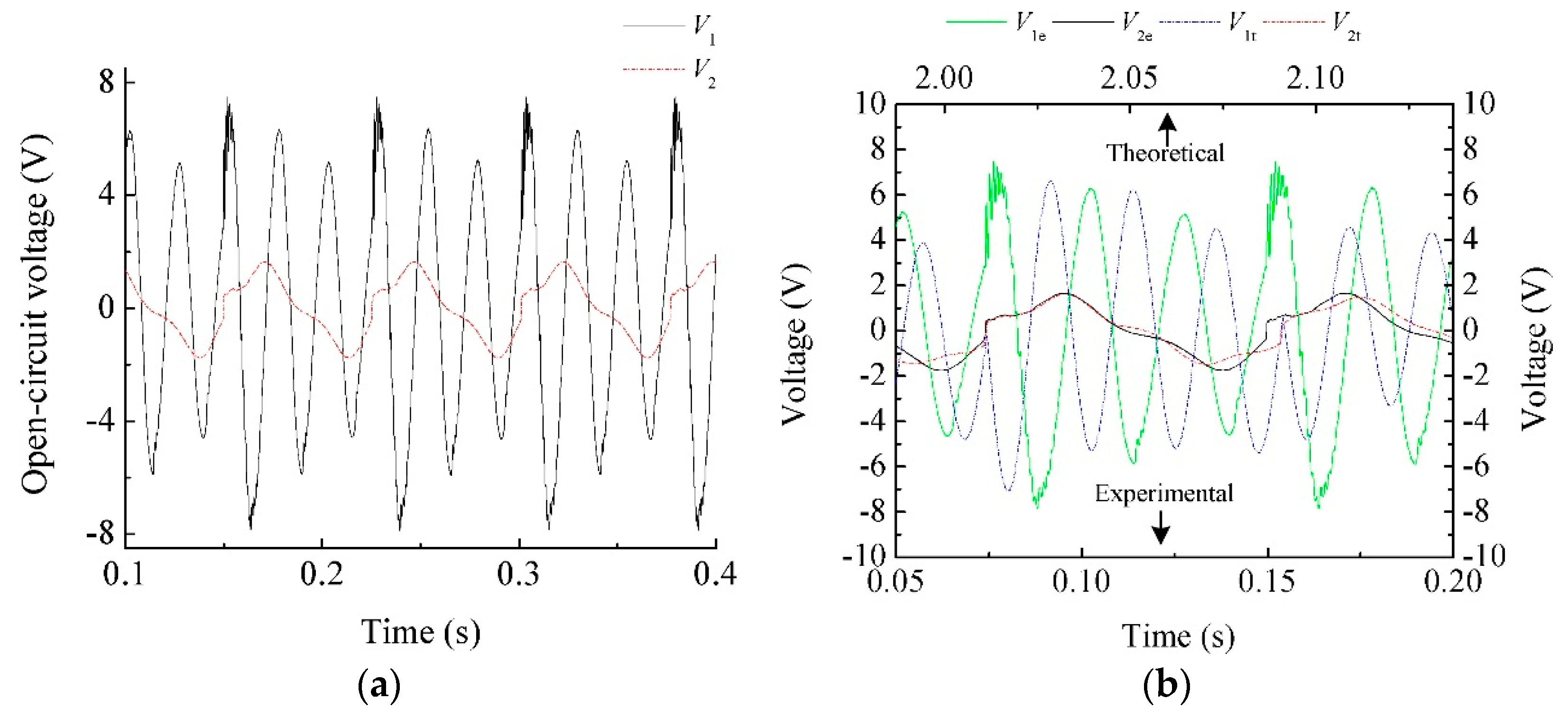
Figure 7 shows the measured open-circuit voltages from PEH and EMEH elements, and a comparison with the theoretical results. It is clear that the experimental results have the similar waveforms as that of the theoretical results. The voltage waveform generated from EMEH seems to be quasi-periodic signal with a root mean square (RMS) value of 1.05 V. This voltage,
V2, jumps from negative value to positive one instantaneously when two oscillators collide. This phenomenon is the same as what described in simulation result, as shown in
Figure 7b. The subscripts “t” and “e” stand for theoretical and experimental results, respectively. However, there are multiple spikes in voltage
V1 during the collision, which are not displayed in the simulation results. According to the
V1 waveform and value of
V2, we can conclude that there are sub-impacts after the first impact [
24]. After the first impact, the piezoelectric beam absorbs some kinetic energy and vibrates in the same direction as that of the magnetic oscillator. Due to the higher fundamental frequency, it reverses its trajectory, catches up with the magnet again, and generates the sub-impacts. The RMS value of
V1 is 4.20 V. Note that some kinetic energy is dissipated in each inelastic collision. Sub-impact will reduce the energy conversion efficiency of the FUCHEH. Accordingly, it is necessary to explore the occurrence condition of the sub-impact and its influence on the output power, in order to optimize the generating performance of the FUCHEH. However, the related research is not the focus of this paper, which will be performed in the future.
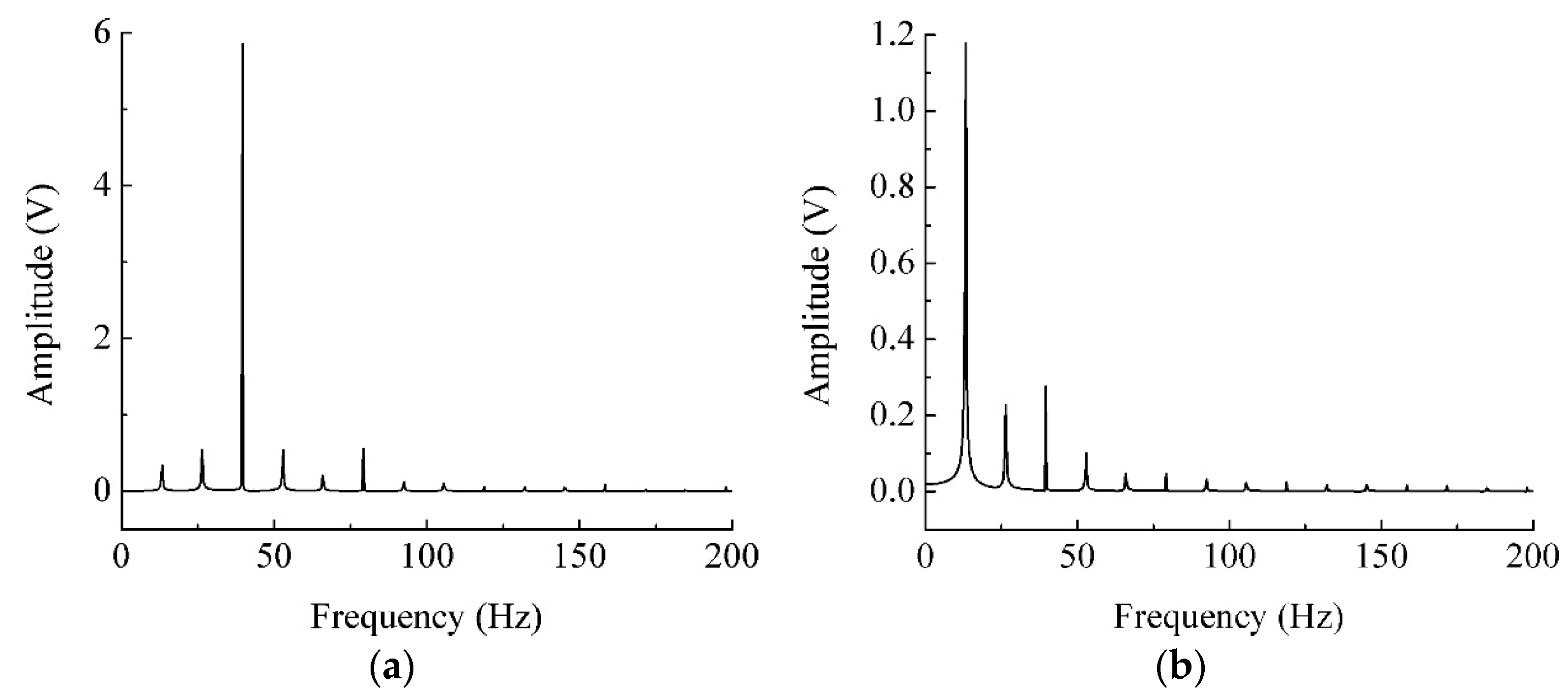
Frequency domain analysis of the time-domain signal can be carried out by using the fast Fourier transform (FFT).
Figure 8 shows the FFT of open-circuit voltage corresponding to
Figure 7a. From
Figure 8a, there are five frequency components for the piezoelectric oscillator. They are 13.3 Hz, 26.3 Hz, 39.6 Hz, 52.9 Hz, and 79.2 Hz. There is no doubt that 13.3 Hz and 39.6 Hz corresponds to the fundamental frequencies of magnetic and piezoelectric oscillators, respectively. 26.3 Hz is close to the value
. That is to say, two oscillators undergo the coupled vibration for a short time after the collision. 52.9 Hz and 79.2 Hz stand for the double frequency components of coupled vibration frequency and fundamental frequency, respectively. In
Figure 8b, only the first three frequencies occupy large weight, i.e., 13.3 Hz, 26.3 Hz, and 39.6 Hz. In a word, impact induces multiple frequency components, resulting in complex dynamic behaviors. It is indicated that the fundamental frequency and the coupled vibration frequency contributes most output voltage for the PEH and EMEH subsystems. Furthermore, sub-impact is mainly affected by the fundamental frequencies of oscillators and coupled vibration frequency.
In order to output the maximum power, the load resistances connected are optimized by experimental tests. Based on the conclusion reported previously [
21], the load resistances
R1 was optimized firstly.
Figure 9a plots the output power of the FUCHEH delivered to different load resistances
R1 for the PEH part. The coil was set to be open-circuit. When the resistance equaled 40 kΩ, the power reached the maximum. After that, the matched
R1 was connected to piezoceramic layers and were kept constant. The load resistance connected to the induction coil,
R2 was optimized and the matched value was 400 Ω, as shown in
Figure 9b.
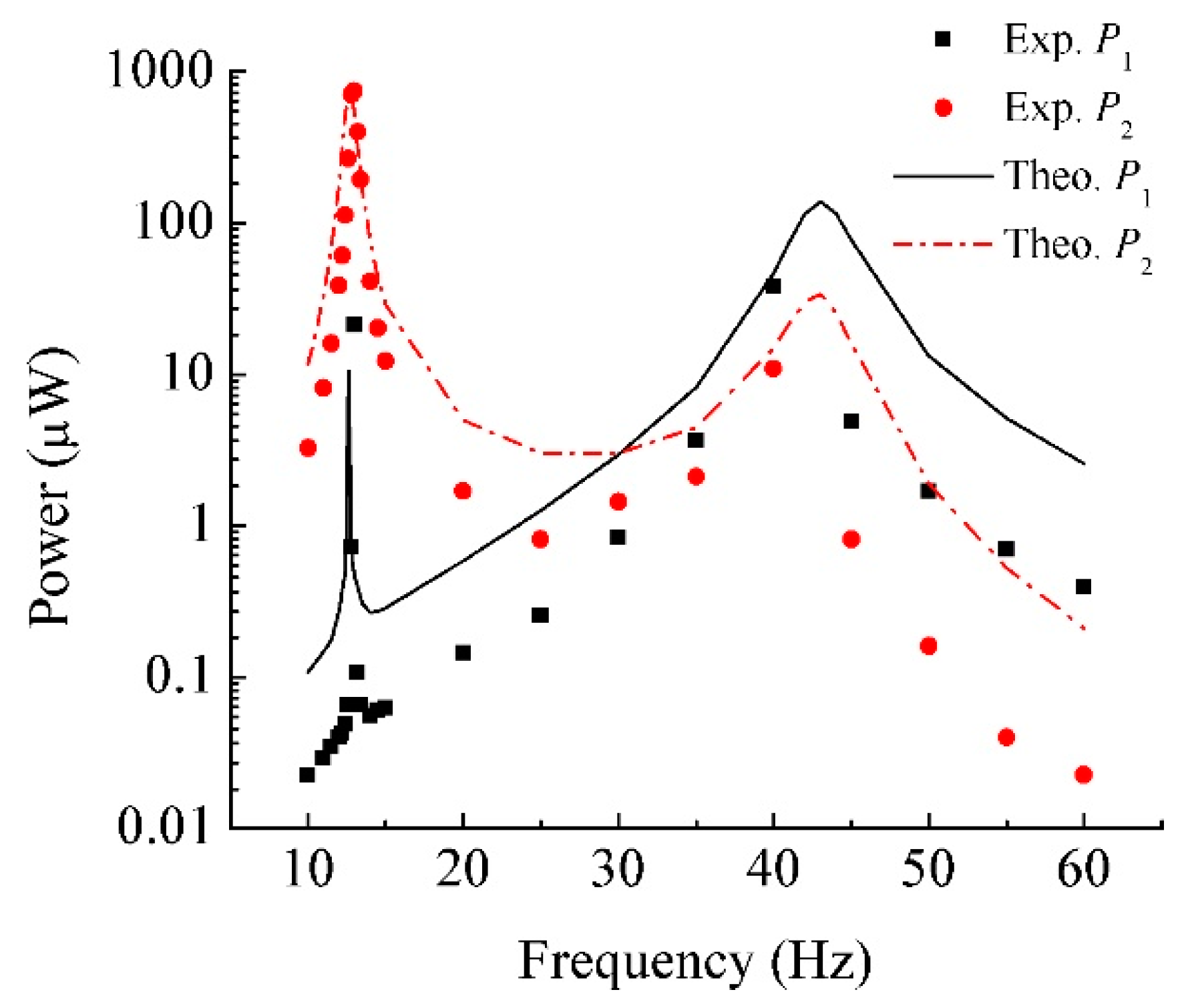
Figure 10 shows the comparison between experimental and theoretical output power frequency responses for the FUCHEH. The matched
R1 and
R2 are connected. The average output power from the PEH (
P1) and EMEH (
P2) subsystems vary with the changing of excitation frequency. It can be seen that the experimental results show the similar trend as that of the theoretical ones. They also agree well with each other at the first resonance. At the second resonance, the noticeable disparity is due to the varying of mechanical damping at higher vibration frequencies. Note that the theoretical values of mechanical damping ratios are presumed to be constant. In this paper, the performance at the first resonance is the focus of attention. The measured
P1 reaches the maximum 21.11 µW at 13 Hz. That is to say, the generating performance of the FUCHEH in the low-frequency range depends on the vibration of the driving oscillator. The measured maximum output power of
P1 is 2.8% of that from the EMEH subsystem (748.02 µW). The reasons for such a large difference in output power can be summarized as two aspects: (1) the electromagnetic damping force consumes some kinetic energy of the magnetic oscillator, resulting in the decrease of kinetic energy transferred to the PEH subsystem through collision. Moreover, the deformation of the piezoelectric patch is small, due to the small size and large stiffness. Consequently, the PEH subsystem generated limited electric power; (2) the capacitive reactance of the PEH subsystem is much larger than the optimized load resistance
R1 under the condition of low vibration frequency, which divided large portion of the output voltage. However, when the scale of the FUCHEH is reduced to micro-scale, this difference will be narrowed. That is because the size reduction of the magnet and induction coil will sacrifice generating performance of the EMEH subsystem.
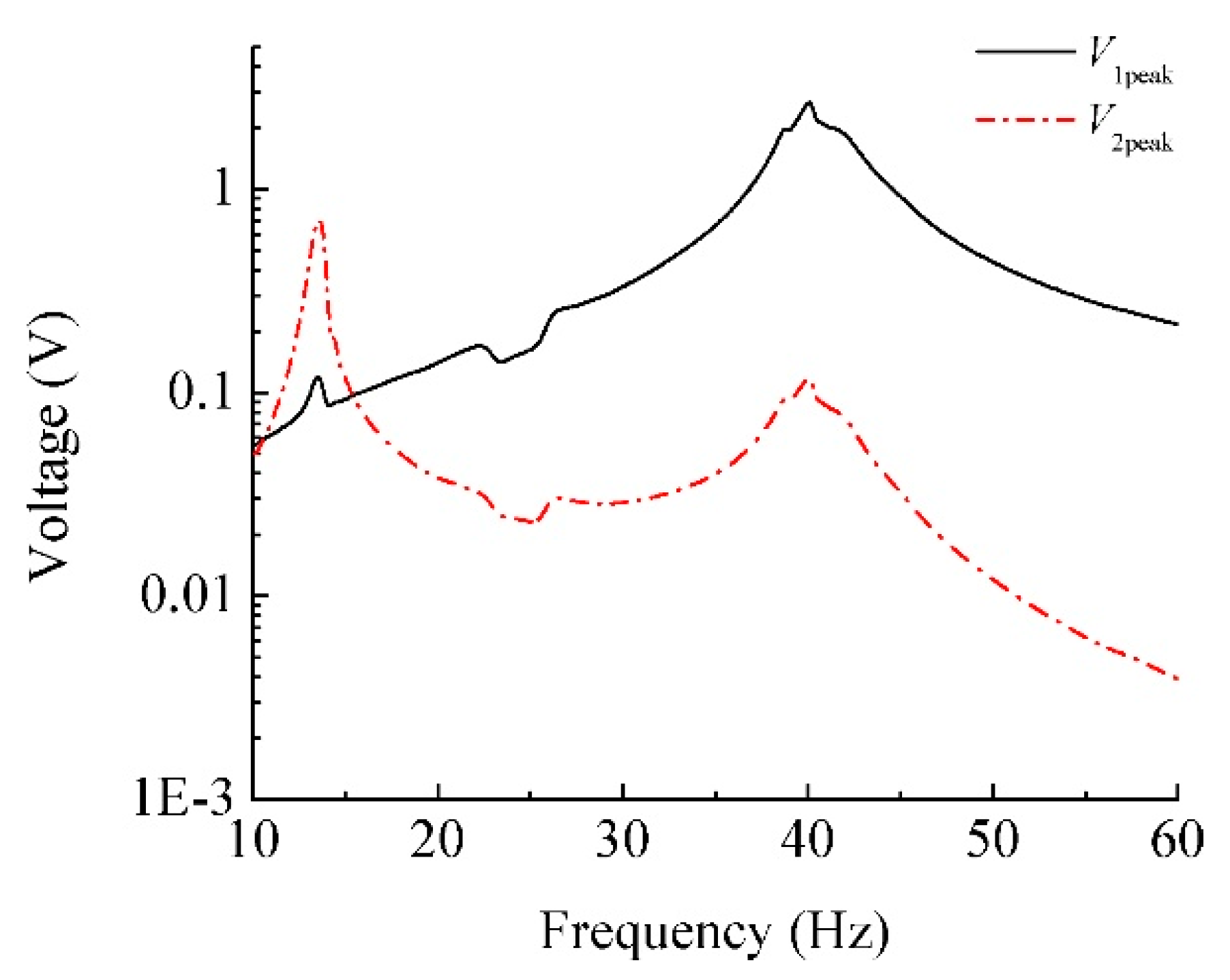
The sweep spectrum analysis was performed in order to search for the resonant frequencies of the FUCHEH, as illustrated in
Figure 11. The excitation frequency was swept from 10 Hz to 60 Hz with the sweep rate 0.5 Hz/s. It is shown that the resonant frequencies locate at 13.5 Hz and 40 Hz, respectively. That is to say, the first resonant frequency shifts to the right, while the second one shifts to the left. The right shift conforms the characteristic of hardening spring, which is induced by the collision between piezoelectric and magnetic oscillators. They act as a flexible stopper for each other. The left shift demonstrates the inherent piezoelectric nonlinearity of PZT-5H [
25].
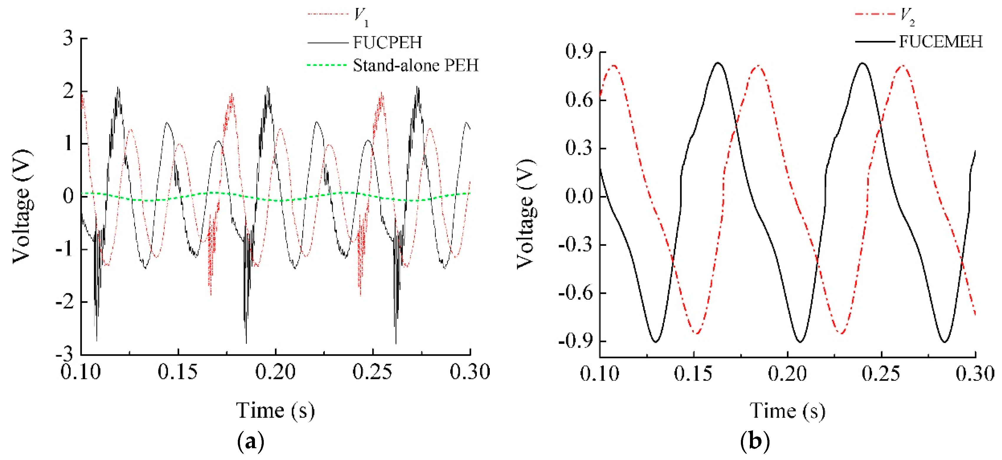
If the substrate B and magnet are removed, the stand-alone PEH is developed, which suffers no effect of impact. Similarly, a frequency up-converting piezoelectric energy harvester (FUCPEH) can be produced when the inductance coil of the FUCHEH is open-circuit. A frequency up-converting electromagnetic energy harvester (FUCEMEH) can be formed when the piezoelectric patches of the FUCHEH are short-circuit.
Figure 12a illustrates the comparison of output voltages from the PEH subsystem, FUCPEH, and stand-alone PEH. The matched
R1 and
R2 are connected. The excitation frequency is 13 Hz. The RMS voltage of the PEH subsystem is 0.919 V, which is 94.5% of that of the FUCPEH (0.973 V) and more than 16 times of that of the stand-alone PEH (0.055 V). Accordingly, the impact-based frequency-up converting mechanism significantly improves the generating performance of PEH in the low frequency environment. Because part of kinetic energy is harvested through the electromagnetic induction, the RMS voltage generated from the FUCHEH is less than that from the FUCPEH. The comparison of output voltages from the EMEH subsystem and FUCEMEH is presented in
Figure 12b. Their RMS values are 0.547 V and 0.553 V. Although the RMS voltages from the subsystems of the FUCHEH are less than that from the frequency up-converting energy harvester with one transduction mechanism, the overall output power of the FUCHEH is 769.13 μW, which is 3249.4%- and 100.6%-times larger than that of the FUCPEH and FUCEMEH, respectively. Consequently, the FUCHEH proposed contributes to improving the generating performance of the conventional FUCPEH in the low-frequency vibration environment.


