1. Introduction
The efficient implementation and use of clean energy resources is one of the greatest challenges that we face as a global society. In recent years, we have witnessed a steady increase in global new investment in renewable energies (from 47
$BN during 2004 to 242
$BN during 2016). Only during 2016, wind, solar, biomass and waste-to-energy, geothermal, and small hydro and marine energy added 138.5 GW of installed capacity between them [
1].
Another approach to clean energy use focuses on small scale energy harvesting (either using photovoltaic or solar thermal technologies) for local use in different building typologies. Buildings consume up to one-third of the total energy supply in developed countries, and up to one-fourth in developing countries [
2]. In recent years, there has been a growing interest about the functionalization of building envelopes in order to reduce its energy consumption. This interest has strengthened the desire to use the building facade for the local production of electricity or the accumulation of thermal energy [
3].
Building-integrated solar thermal (BIST) technologies can be a potential solution towards enhanced energy efficiency and reduced operational costs in contemporary buildings [
4]. Solar thermal is the most mature technology among all currently available solar technologies, proving to have solar conversion efficiencies two to four times higher than solar photovoltaic systems [
2]. Furthermore, solar thermal technologies are of widespread use due to their wide range of applications and large-scale production at global level, assuring cheaper costs and shorter payback periods compared to its lifetime [
5].
Double-skin facades (DSF) are a popular architectural trend, both for their attractive aesthetics and the improvement in internal comfort and building efficiency that can be achieved when used as a building envelope (by acting both as noise and thermal insulation) [
6]. A DSF consists of two skins (a glazed outer layer and either a glazed or mixed inner layer) separated by an air cavity. The cavity can be ventilated (by either atmospheric openings or mechanical ventilation), and in some cases, shading devices might be installed into the cavity to reduce the solar heat gaining inside the building. In mild to cold climates (i.e., Northern Europe), it has been proven that the use of DSF reduces the heating loads during winter and increases the cooling loads of the building during summer [
7]. However, in Mediterranean climates, where large solar gains and moderate to warm temperatures are a permanent condition throughout the year, DSF can lead to indoor overheating even during winter [
8].
DSF are interesting due to their aesthetics or thermal insulation and their potential use as active solar facades (ASF). ASF, besides absorbing and reflecting the incident solar radiation, can also transform part of the absorbed radiation into electricity [
9,
10,
11] or transmit the absorbed thermal energy into the building using mechanical equipment (e.g., pumps or fans on a hydraulic circuit). Quesada et al. [
12] reviewed scientific studies carried out on transparent and translucent ASF during the first decade of this century. Recently, Zhang et al. [
13] presented a comprehensive review on active solar thermal facades (ASTF).
Venetian blinds (VB) mounted behind glazed surfaces are typical shading devices used for daylighting control. VB also have a direct effect on indoor cooling loads and building energy consumption [
14]. A VB-type of structure mounted in a closed-cavity DSF, besides serving its purpose as a shading device, can also be used as a heat exchanger, where the radiation heat absorbed on the VB louvers could be convected into a water stream circulating inside the slats forming the VB; this type of structure would allow for energy recovery and exterior views simultaneously, and can be easily integrated into the facade aesthetical design [
15]. In this work the assessment, by means of computational fluid dynamics (CFD), of the thermal performance of a DSF with a venetian blind-type of structure, mounted in the DSF cavity and used as a solar thermal collector, is presented.
CFD has proven to be a useful tool on the study and optimization of DSF due to its ability to conjoint fluid dynamics, turbulence, thermal and radiation models into a single computer simulation, allowing to parameterize such complex multiphysics problem numerically [
16]. Several authors have previously validated the use of CFD techniques when assessing the thermal performance of DSF. Manz [
17] evaluated the total solar transmittance of a DSF with free convection using CFD techniques. Manz et al. [
18] used CFD to evaluate the thermal performance of mechanically ventilated DSF. Windows and DSF with VB have also been studied by means of CFD modeling [
19,
20]. Previous work by this research group includes a CFD parametric study of the influence of construction and operation parameters on the thermal performance of a DSF [
21], and a DSF with a VB [
22].
CFD has also been used to model and validate the design of solar thermal collectors in order to obtain detailed information on the flow development and temperature distributions in the device. Previous works on this subject include the study of flat plate solar energy collectors [
23,
24], polymer solar collectors [
25,
26], solar collectors with horizontally inclined absorber strips [
27], and tilted wavy solar collectors [
28] on integrated collector storage devices [
29,
30], among others. In all the aforementioned cases, the authors found good agreement between theoretical and/or experimental analysis of the collectors and the obtained CFD simulation results.
For the purpose of this study, a one-storey DSF module with a VB mounted in its cavity (and acting as a thermal collector) was modeled using CFD. The modeled facades were set to be located in Barcelona, Spain, with orientation south, east, and west. For the studied facades, both the reductions in radiative heat gains entering the building and the heat recovery were evaluated for yearlong operating conditions. Thermal efficiencies were estimated for all studied cases.
2. Modeled Case
The geometric/numerical configuration used in this work is based on previous parametric studies in DSF with VB performed by this research group [
8,
15,
21,
22] in order to further analyze the thermal performance achieved by the proposed model. Previous studies were less comprehensive in their time scale (limited to estimate the facade performance during a single summer month), whereas the present work focus on the double skin facade-venetian blind (DSF-VB) model performance throughout a complete operation year.
2.1. DSF-VB Model
The control volume used for CFD simulations (
Figure 1) consists of a one-storey (4 × 4 × 0.28 m) enclosed DSF module, and comprises (from outdoors to indoors) a 6 mm external glazed surface, a 280 mm enclosed cavity with VB and a 6 mm internal glazed surface. The closed cavity was taken to be filled with Nitrogen in order to avoid moisture condensation situations associated with enclosed air and glazing surfaces.
A VB-type of structure consisting of 24 hollow aluminum slats, connected by 180° elbows forming a single hydraulic circuit, was placed in the DSF cavity. This structure acts as a solar thermal collector where the solar radiation absorbed by the slats is convected into a water stream circulating through the serpentine. VB louvers were taken to be hollow rectangular aluminum profiles with dimensions 153 × 13 mm and with a selective black surface treatment to assure high radiation absorptivity and low emissivity [
31]. VB louvers tilt angle (β) was set to 45° to avoid glare issues due to direct day light reflection into the building at high solar elevation angles. For this study, the VB was placed at 6.6 cm from the external glazing [
22].
An isometric view and general geometric configuration of the DSF-VB model used for this numerical study is shown in
Figure 1. 180° elbows connecting the VB louvers are not shown in the figure.
2.2. Material Properties
Table 1 shows the physical and optical properties for all the materials used in the studied model. Thicknesses for the different layers were assigned following common practices in construction.
2.3. Location and Climatic Conditions
The modeled building is assumed to be located in Barcelona, Spain (41.23 N–2.11 E). Climatic data (external air temperature) was obtained from Catalonia’s meteorology agency [
32], which provided raw hourly air temperature data from two different weather stations in Barcelona for the past 25 years. The external temperature data was hourly averaged and then fitted into a 6th-degree polynomial equation representing the hourly air temperature for an average day of each month of the year.
Figure 2 shows an example of the polynomial fitting obtained for the external air temperature in Barcelona on an average day in July.
Table 2 shows the polynomial regressions used to model the external air temperature for each month of the year. This time-dependent temperature profile was introduced as a boundary condition on the outer face of the exterior glass in our CFD software as a user-defined function.
2.4. Meshing
A tetrahedral grid was selected as the mesh to model the nitrogen inside of the cavity. Rectangular prisms were selected to model the glazed surfaces and the interior of the aluminum blinds. A refined mesh around all solid surfaces was set in order to properly model the thermal boundary layers created at the solid-fluid surface contacts. Mesh selection was based on geometrical parameters and previous work by this research group [
21].
Figure 3 shows a detail of the cavity mesh near the external glazing and the louvers.
Mesh independency tests were run for both the cavity and the louvers mesh, imposing constant radiation heat fluxes as boundary conditions and monitoring temperature profiles. Mesh-independent results were obtained for mesh sizes of 4173 kEl for the cavity and 2630 kEl for the louvers [
33].
2.5. Parametric Study
In order to evaluate the influence of certain construction and operating parameters, a parametric study was carried out by means of a set of CFD simulations varying the cavity width, the interior glazing reflectivity, and the water velocity through the VB louvers. The improvement on the DSF-VB thermal collector performance was assessed by measuring the reduction on the solar heat gains through the interior glazing of the DSF-VB module when compared to a base case.
For all the cases studied, the heat flux through the interior glazing was recorded for 1-day operation. Climatic and radiation conditions were set to those of 15 July, around where peak solar radiation is expected for the location.
Table 3 shows the studied cases and the obtained results. The first row of each parameter studied corresponds to the values selected for the base case. As expected, lower solar heat gains were obtained when a higher flow rate circulates through the VB louvers. In addition, heat gains were reduced by increasing the reflectivity of the interior glazing. Decreasing the cavity width, on the contrary, increases the heat gains as it reduces the global heat transfer coefficient of the module. For the purposes of this study, Re = 16,000, an interior glazing reflectivity of 60% and a cavity depth of 280 mm was selected for all forthcoming simulations.
2.6. Boundary Conditions and Solver Set-Up
The studied cases were taken to be a conduction/convection/radiation heat transfer problem involving two fluid zones: an enclosed cavity (filled with nitrogen) and a serpentine (water running through the hollow louvers).
In order to simulate the studied cases, Navier-Stokes equations together with the energy conservation equation were solved using CFD code Ansys Fluent® v16. RNG k-epsilon turbulence model (for the serpentine), a laminar flow model (for the enclosed cavity), and P1 radiation model were selected as numerical sub-models for all cases tested.
A pressure-based double-precision transient solver was selected in order to solve the set of equations used. Second order upwind discretization schemes were imposed on all the transport equations. PISO pressure-velocity coupling was chosen due to its suitability for buoyancy-affected flows. The fluid was taken to be incompressible, Newtonian, and in laminar or turbulent flow regime, depending on the fluid zone. All the numerical sub-models, discretization and simulation strategies were previously validated against an experimental database [
21]. A time step of 120 s was selected for the transient simulations.
Boundary conditions were set as close as possible to DSF regular operating conditions. Time-dependent external air temperature was imposed using a user-defined function based on the polynomial regression discussed in
Section 2.3. Solar radiation dynamics (including the estimation of direct, diffuse and ground-reflected radiation) were simulated using Ansys Fluent v16 Solar Calculator, which estimates the position of the sun with respect to the numerical model for every simulation time step. The superficial velocity of the water running through the aluminum louvers, the cavity depth and the interior glazing reflectivity and emissivity toward the building interior were set according to the parametric study shown in
Section 2.5.
Thermal boundary conditions for the exterior and interior glazing were imposed as convective and radiative heat fluxes and convective heat flux respectively. Convection coefficients were set to 12 W/m
2K and 8 W/m
2K for the outdoors and indoors glazing surfaces, respectively, and the building interior temperature was set to 22 °C during the winter/25 °C during the summer following Spain’s regulations on energy efficiency in buildings [
34].
Nitrogen density and viscosity were set as temperature-dependent. Material physical and optical properties were set as shown in
Table 1. Water inlet temperature and cavity initial temperature (at simulation start time) was set to 25 °C (from April to October) or 22 °C (from November to March) to match the selected building interior temperature.
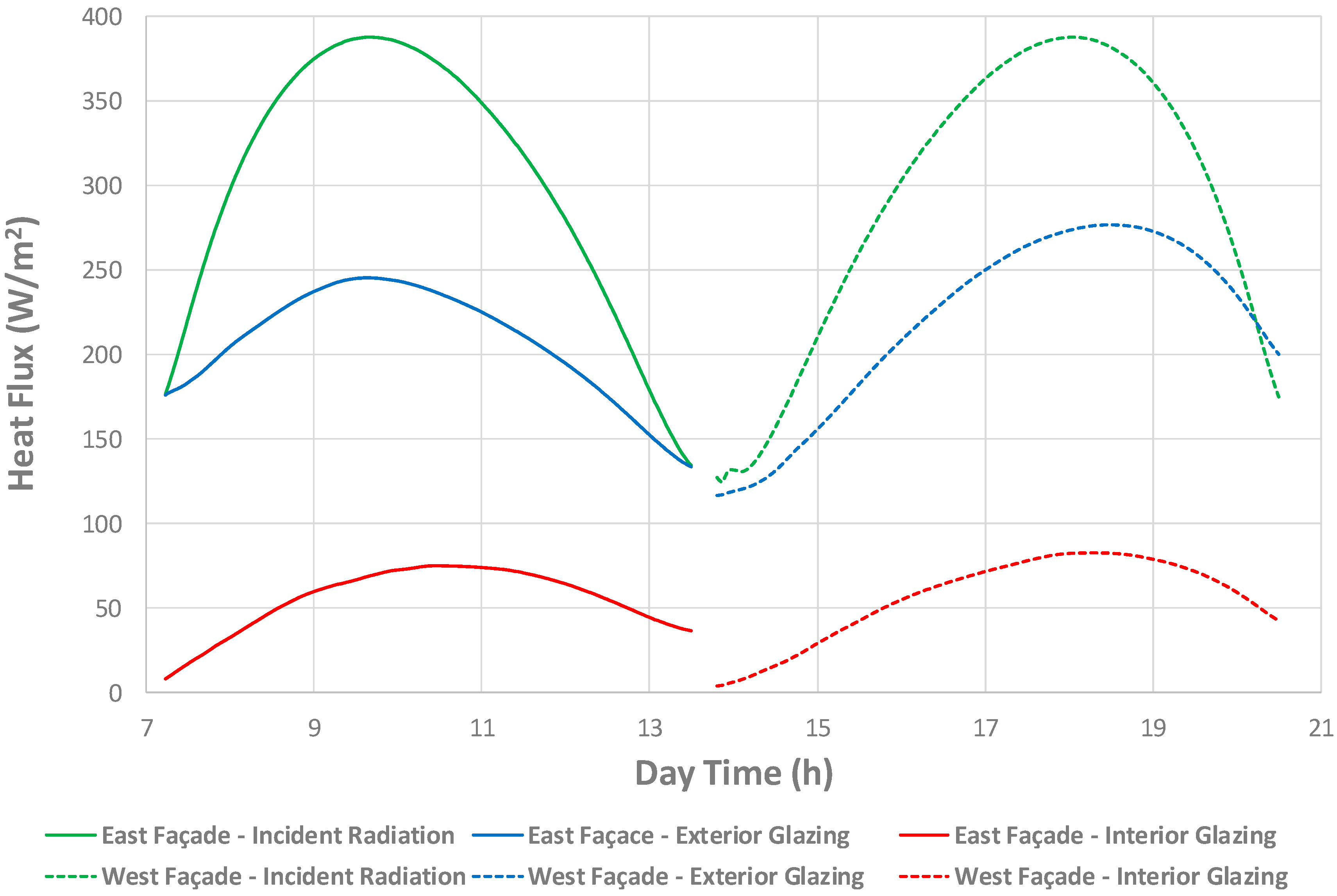
For the South-oriented facade, the simulation time range was set from before sunrise to about sunset for each studied case, for the East-oriented facade the time range comprised from before sunrise until the solar midday, and for the West-oriented facade, this time range went from the solar midday to about sunset for each studied case.
Table 4 shows the initial/final simulation times for all studied cases.
Numerical simulations were performed using up to 24 cores on a Hybrid Bull machine (Barcelona, Spain) (240 cores/20 processors Intel Xeon E5-2697 @ 2.7 GHz (12 cores/processor)/10 Intel Xeon Phi 5120P coprocessors/2.8 TB), property of Consorci de Serveis Universitaris de Catalunya (CSUC). Simulation times ranged from 65 to 120 core hours depending on the studied case. Numerical convergence of the model was checked based on the normalized numerical residuals of all computed variables, set to 1 × 10⁻⁵ for mass, momentum and turbulence equations and 1 × 10⁻⁶ for energy and radiation equations. Heat fluxes and temperatures on all solid surfaces were recorded for analysis and discussion purposes.
4. Conclusions
CFD proves to be a useful tool when modeling conductive/convective/radiative heat transfer in DSF-VB modules. Numerical simulations were run for a yearlong operation of a DSF-VB module for an east-, west-, and south-oriented facade located in Barcelona, Spain.
For the studied cases, a VB-type of structure was included into a DSF module. This setup allows the facade to be used as a heat exchanger, where the absorbed radiation heat is convected into a water stream circulating inside the hollow aluminum slats that conform the VB.
Temperature fields together with heat fluxes through all surfaces were recorded for all studied cases. A previously validated modeling strategy [
11] was used to obtain the presented results, consolidating the idea that CFD can offer tailored solutions for DSF-VB thermal collectors’ performance assessment.
A parametric study was performed in order to evaluate the effect of certain parameters on the building solar heat gains. Lower solar heat gains were obtained when a higher water flow rate circulates through the DSF-VB thermal collector. In addition, heat gains were reduced by increasing the reflectivity of the cavity interior walls and by increasing the cavity width.
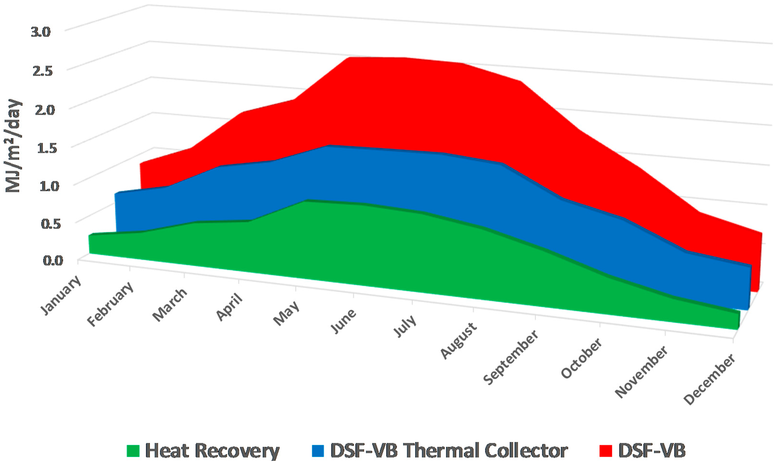
Heat fluxes through the interior glazing of a DSF-VB module with and without heat recovery were recorded to evaluate its thermal performance. For a yearlong operation, a DSF-VB thermal collector can reduce the solar heat gains to 19% (for the east/west facade) or to 22% (for the south facade) of the total incident radiation.
Comparing month-to-month operation, a DSF-VB thermal collector improves the performance of a DSF-VB by reducing solar heat gains by 28% (during winter) to 40% (during summer) when comparing the performance of an east or west-oriented DSF-VB with and without water circulation. For the south-oriented facade these reductions in solar heat gains range between 44% (during winter) and 54% (during summer) when comparing a DSF with and without water circulation.
Heat recovery on the DSF-VB module range from 11% (for the east- and west-oriented facade) and 22% (for the south-oriented facade) of the total incident radiation for a yearlong operation. Heat recovery is larger during the summer period for all studied facades. The thermal energy harvested could be used to partially cover the domestic hot water or heating (during winter) necessities of the building, reducing its primary energy consumption, and improving the building’s carbon footprint.


 ,
, 


