Abstract
Nowadays, micro-porous layers (MPLs) for polymer electrolyte membrane fuel cells (PEMFCs) are commonly deposited onto gas diffusion layer (GDL) substrates starting from hydrophobic carbon-based dispersions. In this work, different quantities of fluorinated ethylene propylene (FEP), a fluorinated copolymer proven to be superior to polytetrafluoroethylene (PTFE) for a proper water management, were used to make both GDL and MPL hydrophobic. After the identification of the optimal amount of FEP, carboxymethylcellulose (CMC) was also added to gas diffusion media (GDM) to reduce overall ohmic resistance of the whole device and adhesion of MPLs to GDLs. Ex-situ chemical and mechanical accelerated stress tests (ASTs) were carried out to accelerate degradation of materials aiming to assess their durability. The highest quantity of FEP in GDMs led to the best electrochemical and diffusive properties. The presence of CMC allowed reducing overall ohmic resistance due to a better electrolyte hydration. A satisfactory durability was proven since the fundamental properties related to gas diffusion medium, such as wettability, ohmic and mass transport resistances, revealed to be quasi-stable upon ASTs.
1. Introduction
Fuel cells are regarded promising devices for clean energy generation for both stationary and mobile applications. Among different types of devices, polymer electrolyte membrane fuel cells (PEMFCs) have been extensively investigated [1,2,3,4,5,6] due to their limited working temperature, high output power density, large and flexible operating range [7]. A fundamental factor for an optimal running of such devices is a correct balanced water management [1,8], which must be properly addressed to have high and constant efficiency during device operation [9]. Indeed, on the one hand, the polymeric electrolyte has to be adequately humidified to guarantee a good proton conduction, while, on the other hand, it must not accumulate too much water [7] to avoid flooding both the channels of the bipolar plates and the porous components [1,8,9,10]. Depending on specific operating conditions and employed materials, liquid water management can be critical both at low and at high current density [11]. In this respect, gas diffusion medium (GDM) is a fundamental component for a PEMFC because it is inserted between the bipolar plate and the catalytic layer [9] aiming to properly manage water which both enters the cell with humidified reactants and is produced by the redox reaction. GDM is formed by a carbon cloth or paper macro-porous substrate (gas diffusion layer, GDL) and a micro-porous layer (MPL) [9]. The latter is a carbon-based hydrophobic film which is directly deposited onto the GDL. In the scientific literature, it is well-established that its use leads to a significant improvement of devices performance, allowing to enhance reactants transport and water removal [1,5], electric contact and electronic conductivity [12,13,14]. Frequently, polytetrafluoroethylene (PTFE) is employed as the hydrophobic agent for both GDL and MPL [1]. The influence on fuel cells performance of GDLs quality and materials, MPLs thickness and wettability, PTFE and carbon loading as well as flow field geometry has been largely studied by many authors [15,16,17,18,19,20,21]. Different quantities of PTFE have been reported as optimal values to get valuable and durable efficiencies; they range from 10% to 30% by weight for backing layers, while keeping around or slightly below 15% for MPLs [20]. Water amount and distribution within the fuel cell is strictly related to working current density, geometry of bipolar plates channels and wettability of involved components. By using neutron radiography, which is being established as a powerful technique to quantify and visualize water in fuel cells, Mishler et al. studied the effect on water transport of several parameters, including PTFE loading in both GDLs and MPLs [11]; they found that highly hydrophobic anodic and cathodic MPLs lead to a more hydrated electrolyte, resulting in lower ohmic losses, while less hydrophobic anodic MPLs may cause channels flooding, even at low current density [11].
Recently, authors demonstrated the effectiveness of replacing PTFE with fluorinated ethylene propylene (FEP) [9] which improved the water management of the whole system and consequently mass transport properties [22,23]. Moreover, the use of FEP allows reducing polymer sintering temperature from 350 °C (for PTFE-based GDMs) down to 260 °C. In this work, different amounts of FEP were employed, both for GDL and for MPL hydrophobization, to identify an optimal composition for obtaining well-performing and durable materials [9]. Indeed, durability is still a critical issue to be faced in fuel cells field in order to achieve a widespread commercialization of these devices and a real competition with conventional energy generators [9]. In this respect, lifetime of automotive fuel cell devices should be around 5000 h at the vehicle operating conditions, while, for stationary systems, an operating lifetime of more than 40,000 h would be desirable [24]. In PEMFCs, drop of performance over time is mainly due to mechanical and chemical degradation, which can affect each component of the cell [5,24,25,26,27]. In GDMs, chemical degradation can be caused by polymer deterioration and carbon corrosion [9,26], whereas mechanical degradation, mainly due to continuous gas flow in the presence of water [25,28], concerns detachment of carbon layer of the MPL and possible dissolution in water.
Various accelerated stress tests (ASTs) have been designed worldwide aiming to assess durability of fuel cells components in long-term running without testing them for thousands of hours [5,24,29,30,31,32,33,34,35,36,37,38,39,40,41,42,43]. Such tests usually combine different critical parameters, such as undesirable humidity, temperatures or load cycling [5] and then evaluate consequent electrochemical and morphological response. A connection between changes in morphological features of GDM and fuel cells electrochemical performance and water transport properties has been demonstrated [5,25,26,33,39,44,45,46,47].
However, at the state of the art, while for the other main components of PEMFCs, standard protocols for testing durability have been established, it is not so for GDLs or GDMs [24,31], even though many research groups tried to determine durability and degradation mechanisms of GDLs or GDMs by means of different routes, such as treatment in hot acidic solution [48], freezing/thawing cycles and fuel starvation [49], employment of cold-start conditions [50], submerging of GDLs in hydrogen peroxide solution [51], soaking GDL samples in liquid water at different oxygen concentrations [5] and water temperature [52] and then monitoring hydrophobicity and porosity changes, weight losses and electrical properties upon stress tests.
Ex-situ methods would be preferable, since they may be helpful to separate GDM response from that one of other components [5]. In a recent work, authors developed chemical and mechanical ASTs on FEP-based GDMs to study their durability and they proved that the main degradation mechanism is the mechanical one which dramatically decreases performance and water management capability [5].
In this work, after the identification of the most durable GDM, among those with the different polymer contents employed, a layer of carboxymethylcellulose (CMC) was applied on the best performing FEP-based sample aiming to improve adhesion of MPL to GDL, GDM mechanical resistance and accordingly durability. Therefore, chemical and mechanical ASTs were applied to these new GDMs following the procedure developed in [53] and then they were electrochemically tested and compared to FEP-based samples.
2. Materials and Methods
2.1. Preparation
Carbon clothes GDLs (SCCG5N, supplied by the Italian company SAATI (SAATI, Appiano Gentile, Italy)) were pre-treated to make them suitable for the subsequent MPL coating. Indeed, a hydrophobic surface is also needed for the backing cloth for avoiding liquid loss (i.e., ink liquid components passing through GDL itself) during the coating process. GDLs were soaked in a 12% by weight FEP solution for 20 min and then heat treated at 260 °C for 30 min. All GDLs were subjected to the same treatment since in this work we only aimed to assess influence of FEP content in the MPLs on fuel cell performance.
On the basis of previous works by the authors [53,54], MPLs were prepared from inks containing, as carbonaceous phase, both carbon black (Vulcan XC72R from Cabot Italiana S.p.A., Ravenna, Italy) and multi-wall carbon nanotubes (CNTs, NTX1 (Nanothinx S.A., Patras, Greece)) [28]. The latter (10% by weight) were used to make final coatings more conductive [5] than those based on the unique pure carbon black (CB) [5]. Moreover, FEP (fluorinated ethylene propylene) was employed as hydrophobic agent instead of commonly used PTFE, due to already proven higher hydrophobicity of the final product [23]. Therefore, based on the preparation described in [23], a FEP suspension (55% by weight), supplied by DuPont Italiana S.r.l. (Milan, Italy), and isopropyl alcohol (IPA (Sigma Aldrich S.r.l., Milan, Italy)) were mixed in deionized water; then, CB and CNTs were gradually added. The mixture was stirred and homogenized by a high shear mixer (UltraTurrax T25 (IKA-Werke GmbH, Staufen, Germany)) for ten minutes [5,23]. Four different mass ratios FEP/(CB + CNTs), from 0.03 to 0.12, were employed. The so-obtained inks were deposited onto FEP pre-treated GDLs by means of a doctor blade device to create MPLs [23], which were heat trea ted up to 260 °C, as reported in [23]. The preparation procedure for obtaining the final GDM is schematically reported in Figure 1.
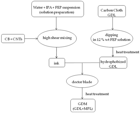
Figure 1.
Schematic representation of gas diffusion medium (GDM) preparation.
Moreover, carboxymethylcellulose (CMC) (Lamberti S.p.A., Albizzate, Italy), a well-known rheology controller and wettability modulator, which has already been used in this field [53,55,56], was also employed to consolidate surface layers improving adhesion between MPL and GDL and to enhance durability of the best performing FEP-based MPLs. Accordingly, the prepared MPL was additionally surface-treated with a CMC (0.75% by weight) solution, which was sprayed onto the MPL side (i.e., the one facing the electrode within the fuel cell), followed by a drying process at 120 °C for 30 min.
2.2. Characterization
Static contact angles measurements were performed, on the MPL side, according to the sessile drop technique using an OCA 20 instrument (Dataphysics, Filderstadt, Germany). Values reported in this work are the result of the average of ten measurements for each sample [5].
Electrochemical tests were carried out at two temperatures (60 °C and 80 °C) and two relative humidity conditions (80–100% and 80–60%, anode–cathode, respectively). Flow rates were 0.25 and 1.0 NL min−1 for hydrogen and air, respectively [5]. Such values correspond to stoichiometric ratios of 1.2 for hydrogen and 2.0 for air, both calculated at 30 A. A commercial catalyst coated membrane (CCM), supplied by Baltic Fuel Cells, Schwerin, Germany, with an active area of 23.04 cm2 was employed as membrane electrode assembly (MEA). Platinum loading was 0.3 and 0.6 mg cm−2 at the anode and at the cathode, respectively and the used electrolyte was Nafion 212 [5].
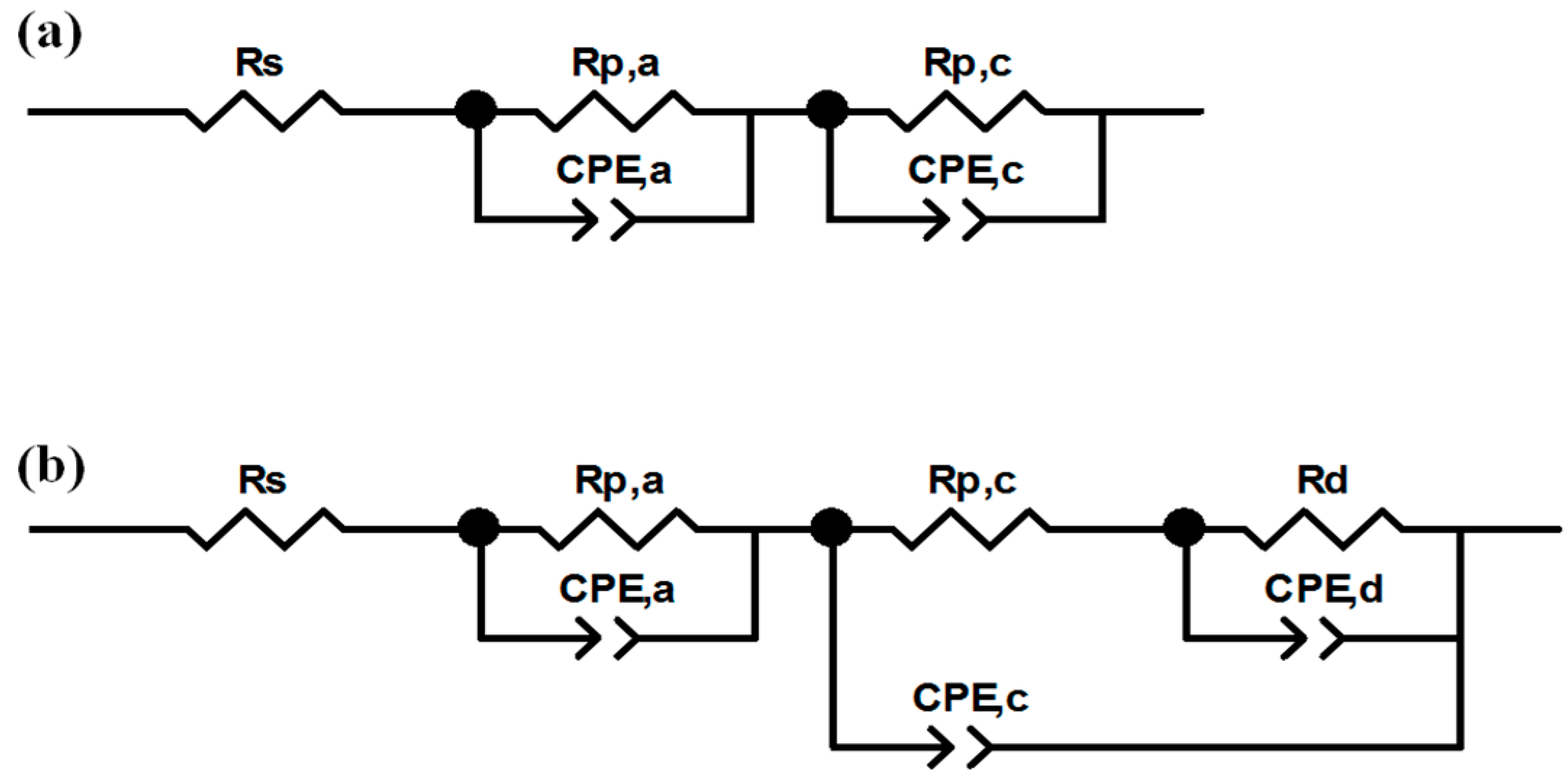
Polarization and power density curves were obtained, under galvanostatic mode, in the current density range from open circuit voltage (OCV) to 1.32 A cm−2, with steps of 0.088 A cm−2. At the same time, electrochemical impedance spectroscopy (EIS) was carried out using a frequency response analyzer (FRA, Solartron 1260) (Solartron Group Ltd., Bognor Regis, UK), in the frequency range from 0.5 Hz to 10.0 kHz [5]. The typical spectrum of an operating fuel cell is composed of one, two or, more rarely, three arcs, whose origin can be ascribed to activation polarization and concentration polarization [5]. The ZView software (Scribner Associates, Southern Pines, NC, USA) was employed to fit experimental data by means of the equivalent circuits shown in Figure 2, and already described in an authors’ previous work [5], which had been developed by modifying the models described in [57,58]. At low current density, the equivalent circuit (Figure 2a) consists of a resistance (Rs) in series with two parallel resistance/constant phase element circuits, Rp,a/CPE,a and Rp,c/CPE,c [5,57]. Rs, also named high frequency resistance (HFR), models the overall ohmic resistance, while the parallel circuits model the anodic (Rp,a/CPE,a) activation polarization losses (i.e., charge transfer resistance at the anode), when visible, and cathodic ones (Rp,c/CPE,c) which are always visible and more pronounced. At medium and high current density, the parallel circuit Rd/CPEd is added in series with cathodic charge transfer resistance (Figure 2b) [5,58] to model concentration polarization losses due to diffusive limitations. Constant phase elements (CPE) were used instead of pure capacitances to consider the capacitive losses [5] due to porosity of electrodes [12,47].
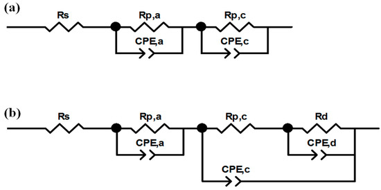
Figure 2.
Equivalent circuits employed for getting electrochemical parameters from electrochemical impedance spectroscopy (EIS) experimental points: at low current (a); and at high current (b).
After determining electrochemical behavior of samples, fuel cells assembled with such GDMs were run at constant current density (0.5 A cm−2) for 1000 h to test their durability at a point that was regarded typical of energy generation for actual prototypes; the voltage degradation rate (µV h−1) and the global cell efficiency over the time were considered as significant parameters for the system evaluation [5]. The simplified expression of the fuel cell efficiency is the following equation [59]:
where ηfu is the fuel utilization, which is the ratio between theoretically calculated hydrogen flow rate and actual hydrogen flow rate, HHV is the hydrogen higher heating value, n is the number of electrons involved in the redox process, F is the Faraday constant and E is the actual working potential.
Η = nFEηfu/HHV
2.3. Accelerated Stress Tests
Two ex-situ accelerated stress tests (ASTs) were developed to analyze the effect of both mechanical and chemical degradation phenomena of GDMs on fuel cell performance. The chemical AST consisted in soaking GDMs in a 20% by volume sulfuric acid solution [5] at a pH value which was far below the typical environment PEM fuel cell pH (2–3), for a total time of 1000 h. This condition was expected to accelerate the chemical degradation of GDMs [28].
The mechanical AST was based on a literature study [25], but a simpler system was set up and already adopted in Reference [5]. A dummy cell was assembled with two GDMs at anodic and cathodic side, separated by a Nafion 212 pure membrane, namely without any catalyst to avoid any possible chemical or electrochemical stress. Only air was supplied to either side [28] with twofold flow rates with respect to those employed during standard running (0.25 and 1.0 NL min−1 for hydrogen and air, respectively) for making mechanical degradation faster [5]. Air was fed for 1000 h continuously, therefore multiple compression/decompression cycles were avoided. The purpose was to test GDMs mechanical resistance and endurance of MPLs, namely the ability of MPLs to avoid detachment from the GDL substrate, and to relate ASTs effect to fuel cell performance.
Properties of the stressed GDMs were evaluated at the end of the ageing treatment. Operating conditions for running cell tests after ASTs were set at 60 °C and relative humidity (RH) (A-C) 80–100%, where the highest efficiencies were achieved for non-damaged samples [28].
3. Results and Discussion
3.1. Static Contact Angle Measurements
Average values of contact angles, obtained at room temperature on GDMs upon thermal treatment, are shown in Table 1.

Table 1.
Static contact angle values of gas diffusion media (GDM) with different fluorinated ethylene propylene (FEP) content.
Superhydrophobic surfaces (i.e., static contact angles higher than 150 °C) were obtained except for FEP-3 sample, which however lies very close to the boundary of superhydrophobicity. Differences are not dramatic and, since no macroscopic change in surface depending on FEP amount in the MPL was found (see Supplementary Materials, Figure S1), they might be attributed to the quantity of polymer which was used in the hydrophobization treatment: a higher amount of FEP led to a better hydrophobicity of MPLs surface, which should positively influence the water removal efficiency of the fuel cell.
3.2. Electrochemical Characterization
Results of the electrochemical tests carried out with MPLs containing different amounts of FEP are shown in Figure 3.
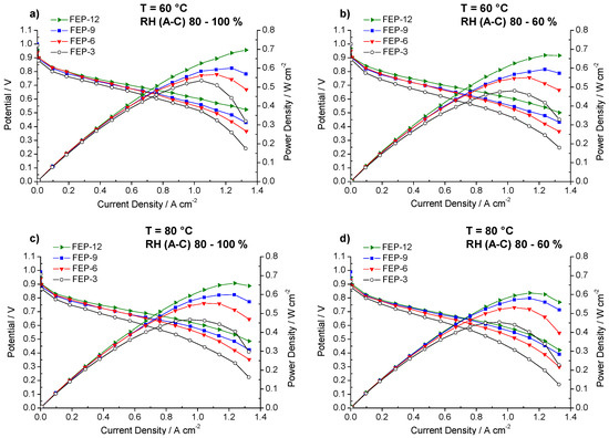
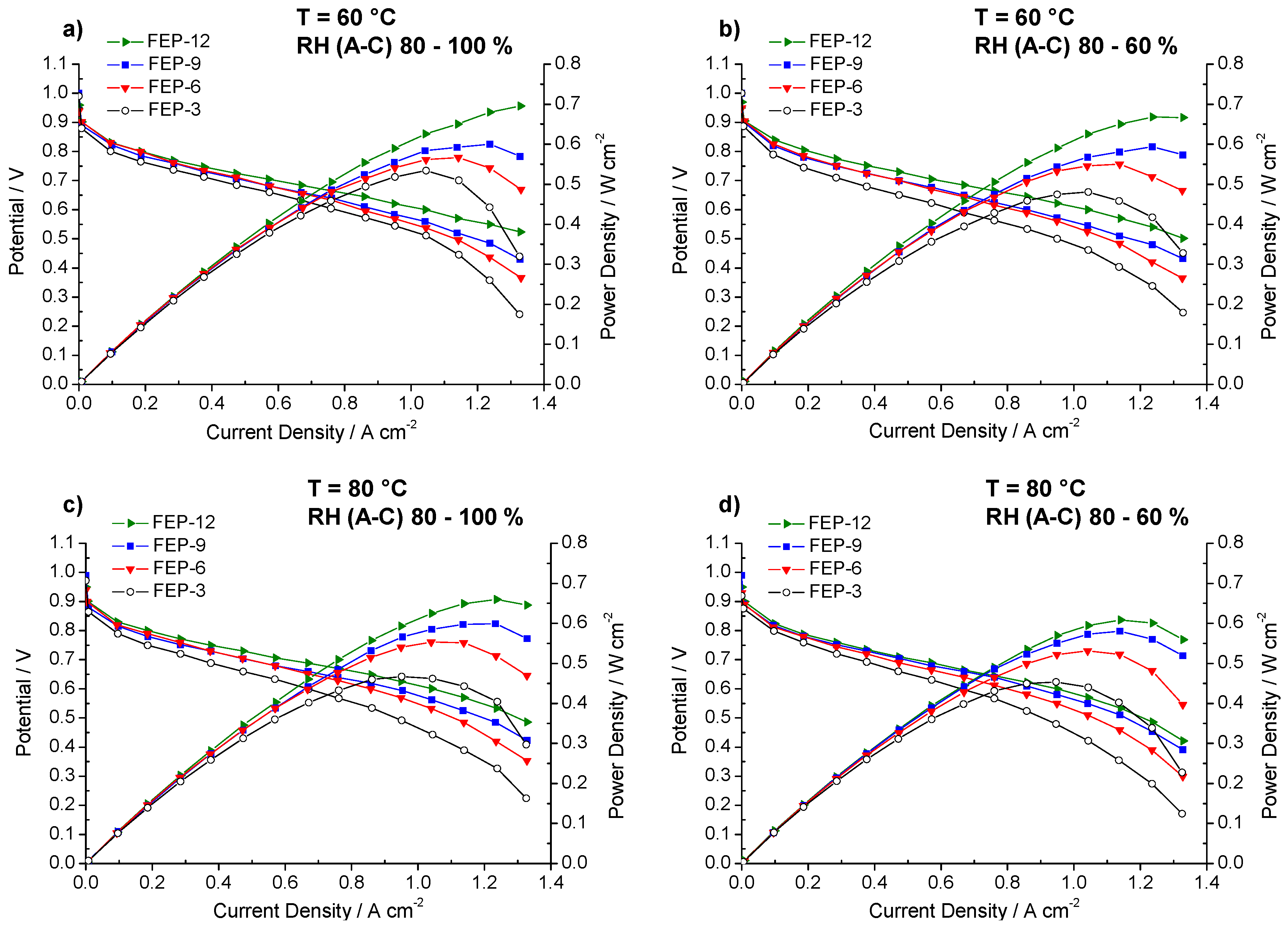
Figure 3.
Polarization and power density curves obtained for fuel cells assembled with all the prepared GDMs. Operating conditions: (a) 60 °C, relative humidity RH (anode-cathode) (A-C): 80–100%; (b) 60 °C, RH (A-C): 80–60%; (c) 80 °C, RH (A-C): 80–100%; and (d) 80 °C, RH (A-C): 80–60%.
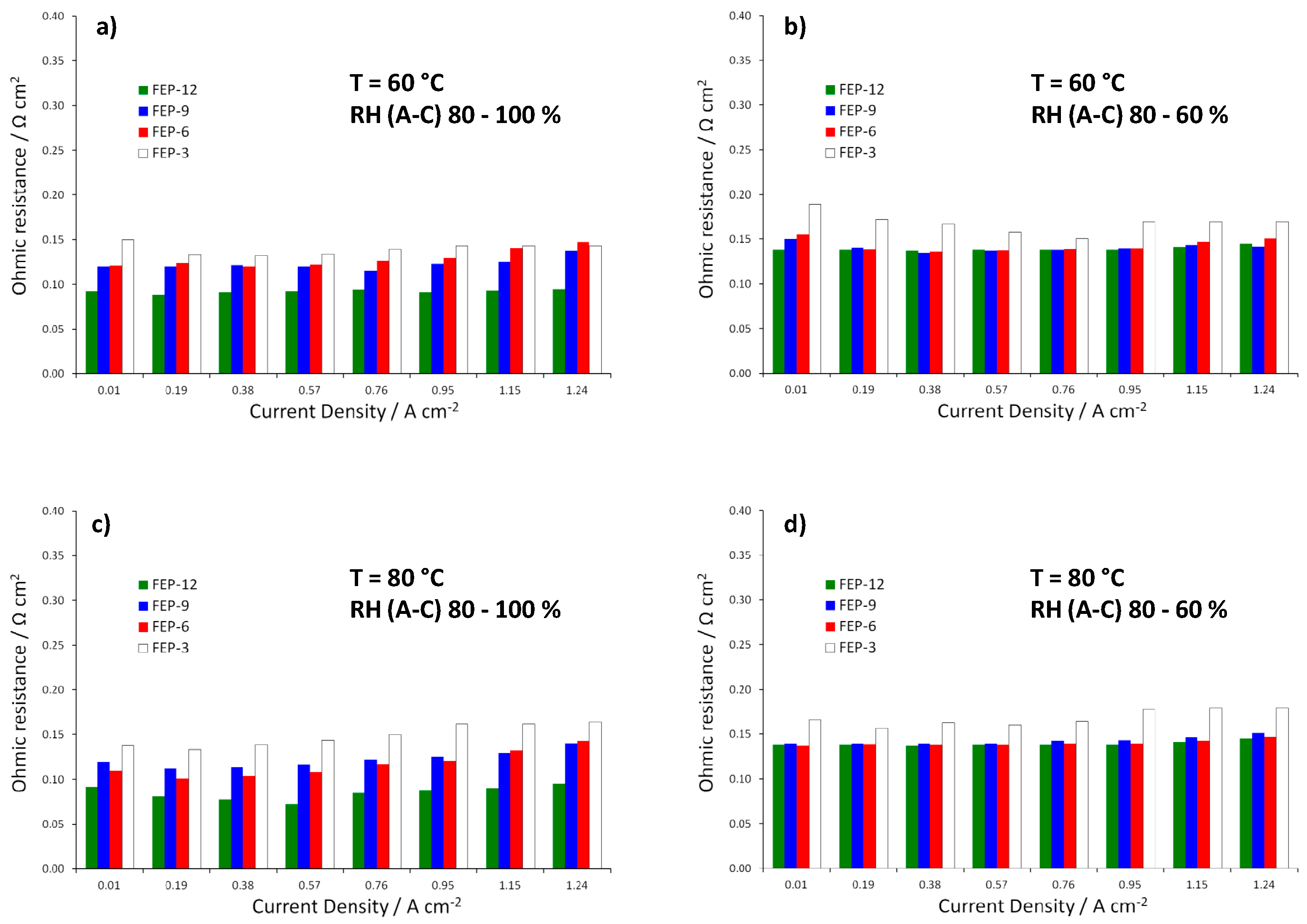
MPLs containing the maximum amount of FEP, i.e., 12% by weight, allowed obtaining, at each operating condition, the best electrical performance. Particularly, at 60 °C and high relative humidity (Figure 3a), the highest quantity of FEP allowed to achieve the maximum power density value, close to 0.7 W cm−2. Fuel cell assembled with such samples achieved the highest output power density and the lowest slope of polarization curves in the high current density regions, meaning that lower concentration polarization losses were obtained [6]. Such a finding may be due to higher hydrophobicity, resulting from static contact angle measurements. A better water-repellent effect should be the reason for a more efficient removal of the excess water, produced by the cathodic reduction reaction. In fact, some differences in performance, even though less sharp, can also be noticed at low and medium current densities, where water management should not have any dramatic effect. Such behavior could be likely ascribed to a slightly higher compression due to a thicker MPL. This might improve charge transfer and reduce contact resistance between MPL and MEA and accordingly overall ohmic resistance. Indeed, this hypothesis can be confirmed by observing the trend of ohmic resistance (i.e., high frequency resistance, HFR, obtained by fitting experimental EIS data), which is reported in Figure 4. FEP-3 shows the worst behavior since fuel cells assembled with such MPL exhibited the highest ohmic resistance at each operating condition. Such results may help to clarify the behavior of the different samples even at low current density which would not be simple by analyzing the only polarization curves. Moreover, a connection between polarization curves slopes and HFR values can be identified, even though not sharp: lower HFR were obtained for lower slopes for all the tested samples.
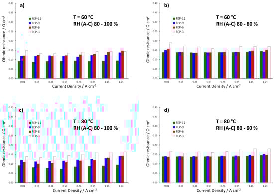
Figure 4.
Trend of ohmic resistances (i.e., high frequency resistances, HFRs) obtained from EIS measurements for fuel cells assembled with all the prepared GDMs. Operating conditions: (a) 60 °C, RH (A-C): 80–100%; (b) 60 °C, RH (A-C): 80–60%; (c) 80 °C, RH (A-C): 80–100%; and (d) 80 °C, RH (A-C): 80–60%.
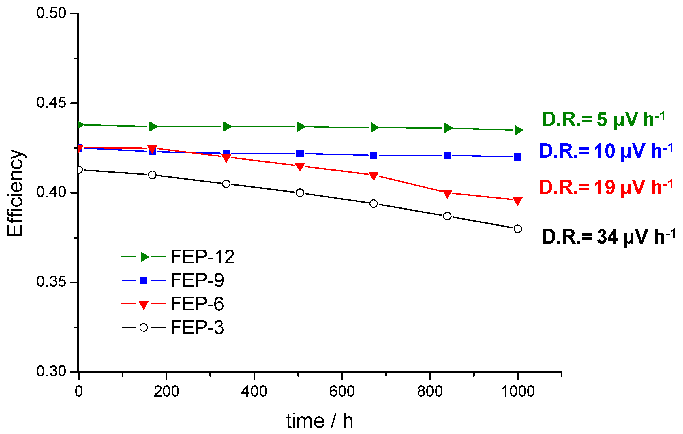
After polarization tests, fuel cells were run at constant current density (0.5 A cm−2) for 1000 h at 60 °C and RH 80–100%, i.e., where the best performance in terms of output power and polarization was achieved [28] (see Figure 3) for the tested samples, especially for FEP-12.
The global efficiencies of the cells with the four different GDMs were calculated after monitoring the voltage [5] and are reported in Figure 5, which shows that they are rather constant over time. In fact, low degradation rates were obtained: 5, 10, 19 and 34 µV h−1 for GDMs with 12%, 9%, 6% and 3% by weight of FEP, respectively; it is worth noting that degradation rate of the used commercial CCM (from Baltic Fuel Cells) at the same operating condition is 30 µV h−1, as was reported in Reference [5]. As expected from the polarization curves analysis, the MPL containing 12 wt % of FEP exhibited the highest average efficiency; anyway, the efficiency values related to the other MPLs are also satisfactory, since they are slightly higher or close to 40%.
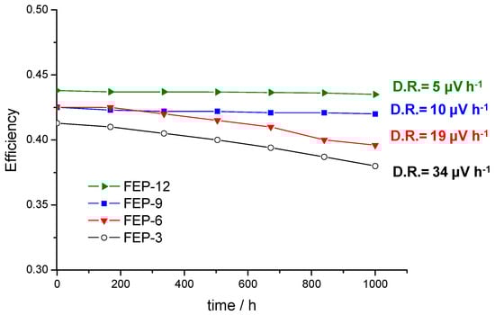
Figure 5.
Fuel cell global efficiencies as a function of time and degradation rate values in constant current durability tests for cells assembled with GDMs based on different FEP content.
3.3. Accelerated Stress Tests (ASTs)
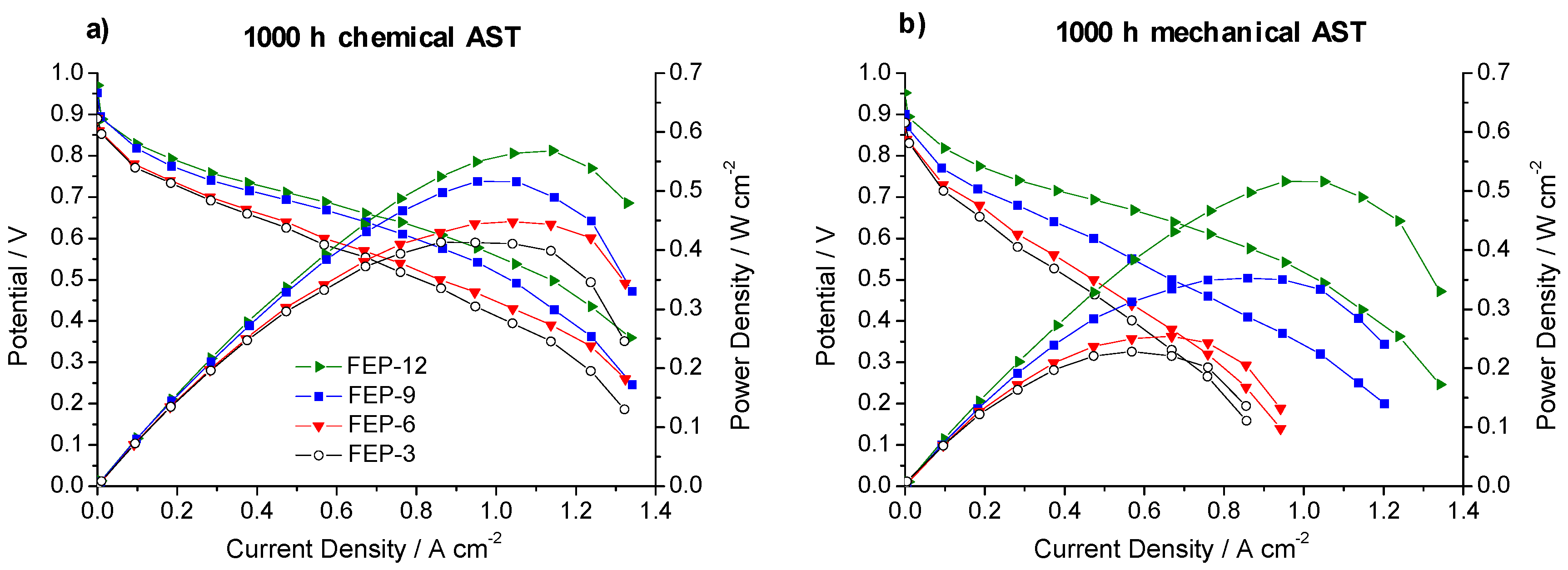
Figure 6 shows polarization and power density curves obtained on chemically and mechanically stressed GDMs after the whole test time (1000 h).
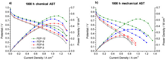
Figure 6.
Polarization and power density curves, obtained upon 1000 h of: chemical (a) and mechanical (b) accelerated stress tests (AST) for FEP-based GDMs.
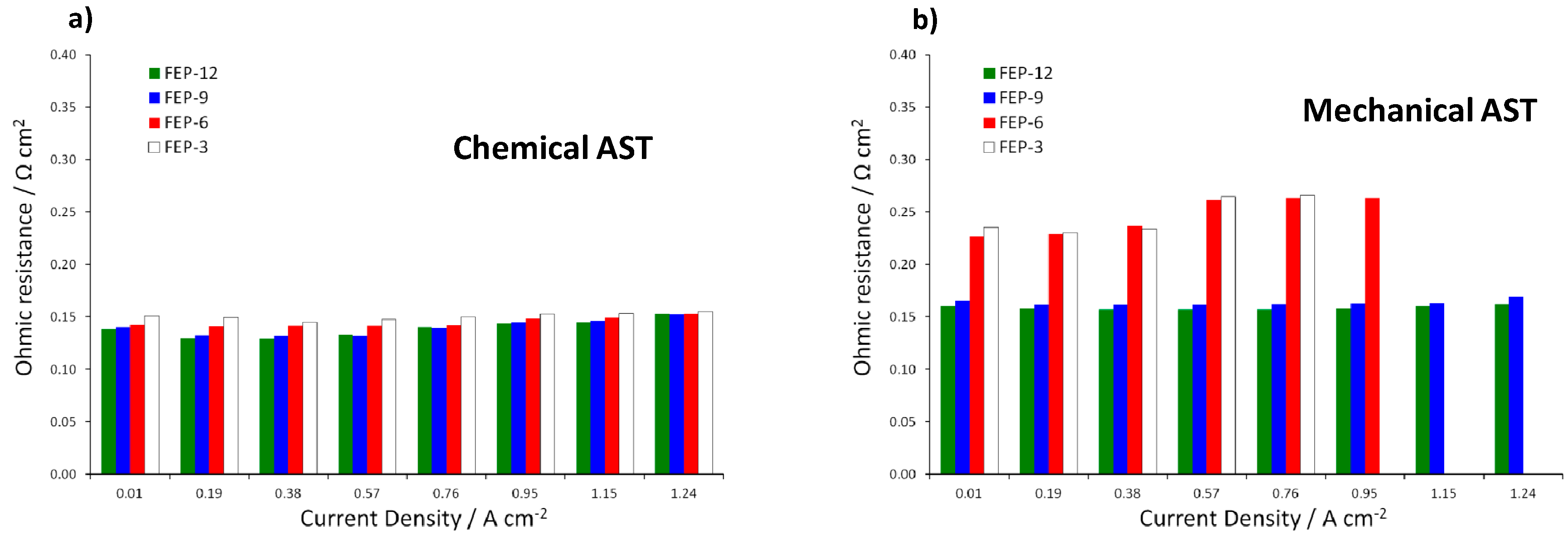
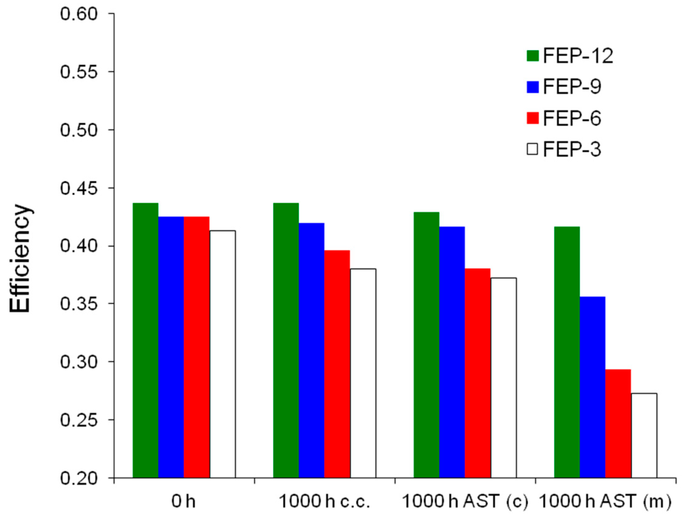
It is evident that the most durable GDM is FEP-12 sample, since it keeps showing the highest electrical performance after both chemical and mechanical AST. A confirmation of such behavior can be found in Figure 7, which exhibits ohmic resistance trend as a function of current density upon both chemical and mechanical AST. Mechanical AST dramatically caused increase of ohmic resistance and this is more evident for lower contents of FEP in MPLs. In addition, in Figure 8, showing global efficiency values at 0.5 A cm−2 for fresh materials (0 h) and for 1000 h stressed ones, both by constant current tests and by ASTs, it is clear that GDM with the maximum content of FEP guaranteed the best durability, since efficiency kept practically constant for all the performed tests. After analyzing Figure 6, Figure 7 and Figure 8, it could be inferred that the mechanical AST led to more deteriorated GDMs than the chemical AST (see Figure S2, Supplementary Materials); indeed, mechanically aged samples exhibited lower electrical performance, especially at high current density. It could be stated that mechanical degradation is more detrimental for mass transport properties of GDMs, as already found in Reference [5] for similar samples.
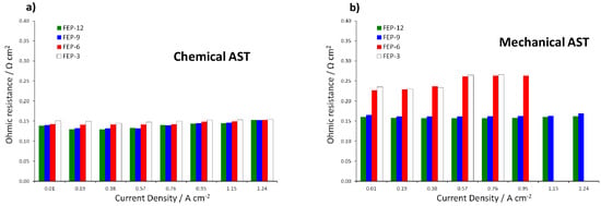
Figure 7.
Ohmic resistance as a function of current density upon: chemical (a); and mechanical (b) ASTs on all the prepared GDMs. Notice that missing values are due to sudden voltage drop at medium-high current density for mechanically aged FEP-3 and FEP-6 samples.
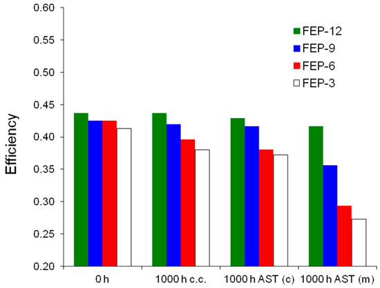
Figure 8.
Global efficiencies obtained for fuel cells assembled with fresh (0 h, not stressed), constant current (c.c.) aged, chemically (AST (c)) and mechanically (AST (m)) stressed FEP-based GDMs.
Again, FEP-12 revealed to be the most durable sample compared to the other ones. This better behavior can be attributed to the higher polymer content which could carry a better adhesion out, after the sintering process, between MPL and GDL substrate [60].
Then, as described in the Materials and Methods section, a CMC layer was applied on the MPL aiming to improve durability and adhesion of such layer to its substrate. Figure 9 shows polarization and power density curves, at each operating condition, of FEP-12 and of CMC-treated GDM with the same FEP content (hereafter named CMC-FEP-12).
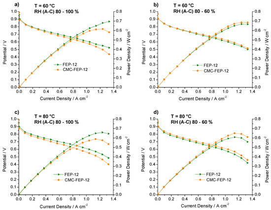
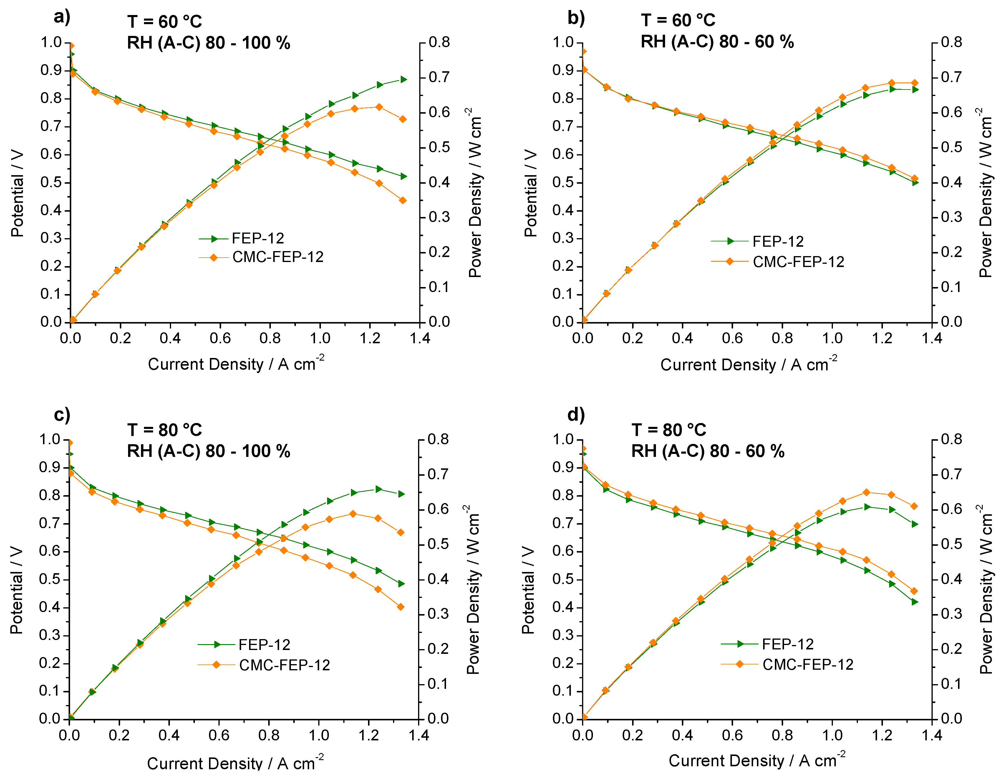
Figure 9.
Polarization and power density curves of FEP-12 and CMC-FEP-12 assembled fuel cells. Operating conditions: (a) 60 °C, RH (A-C): 80–100%; (b) 60 °C, RH (A-C): 80–60%; (c) 80 °C, RH (A-C): 80–100%; and (d) 80 °C, RH (A-C): 80–60%.
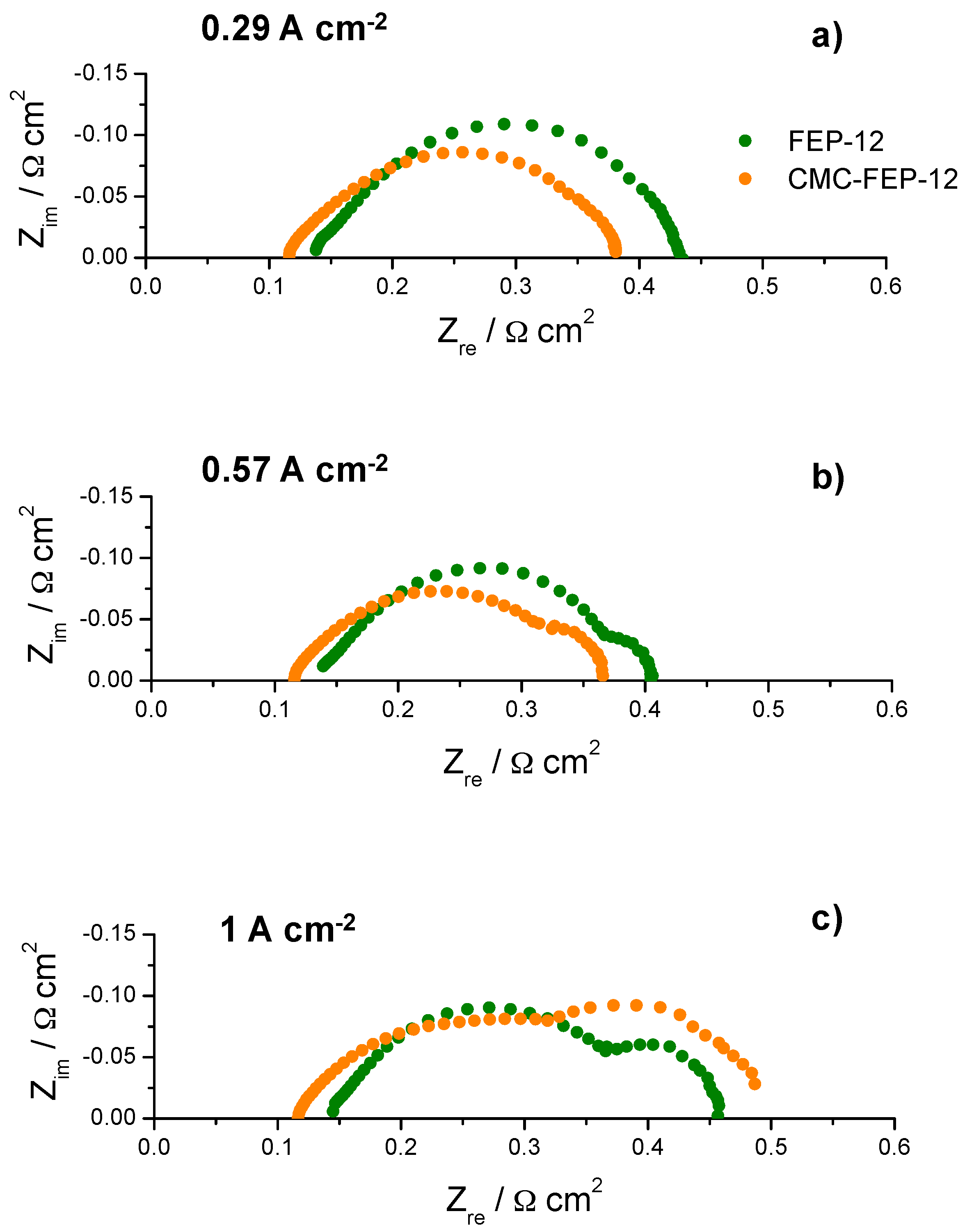
In this figure, it is evident that the presence of CMC on the MPL surface (which has been inferred by observing CMC thermogravimetric analysis, reported in Figure S3, Supplementary Materials) is effective in improving slightly electrical performance at low cathodic RH, both at 60 °C and 80 °C. This was also an important finding of authors’ previous works [53,55] which used CMC as a rheological controller of PTFE-based inks for MPLs deposition. Such behavior at low RH may be ascribed to the hydrophilic nature of CMC which acts as a water reservoir leading to a better hydration of the polymeric membrane; accordingly, a higher proton conductivity and a lower ohmic resistance are obtained. In fact, an example of impedance spectra, obtained at 60 °C and low (i.e., 60%) cathodic RH, is reported in Figure 10. The high frequency resistance, namely the ohmic resistance of the whole device, for CMC-containing GDMs is always lower than that one of FEP-12 GDMs and it also keeps rather constant upon increasing current density. While activation polarization resistance seems to be constant—indeed it depends mostly on catalytic activity, which, in our case, is commercially fixed—the mass transfer resistance, i.e., the contribution at low frequency range, dramatically increases upon increasing current density. This is an ascertained finding which is due to a higher production of water; particularly, samples with CMC show, only at high current density, a slightly larger resistance, due to its hydrophilic feature which retains water and could influence its efficient removal.
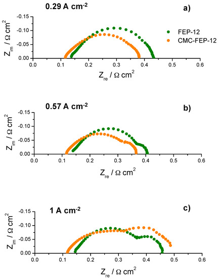
Figure 10.
Example of typical impedance spectra obtained (at 60 °C and RH (A-C): 80–60%) for fuel cells assembled with FEP-12 and CMC-FEP-12 samples at: low current density (a); medium current density (b); and high current density (c).
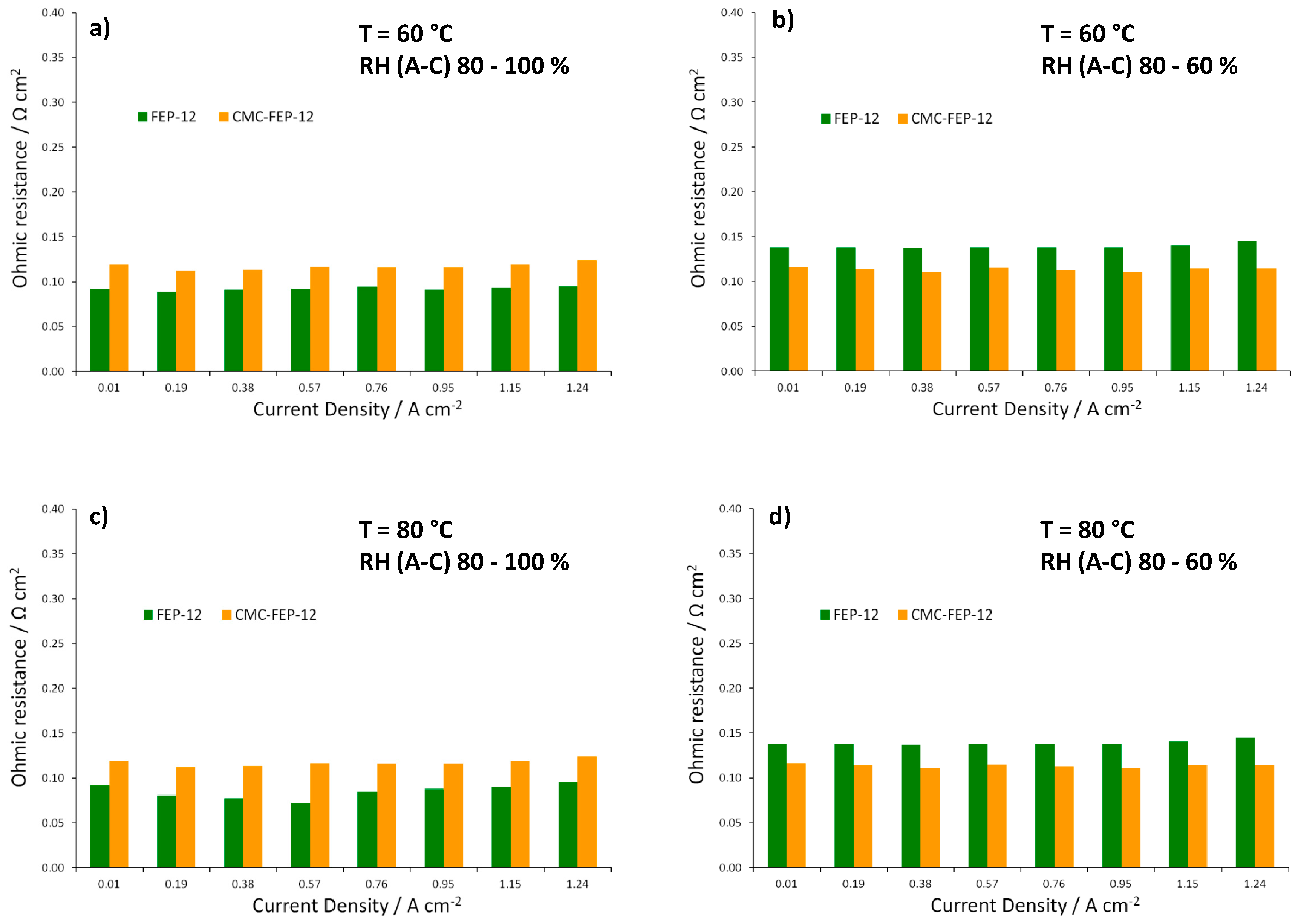
Figure 11, showing ohmic resistances obtained from EIS spectra at each operating condition, confirms the effectiveness of CMC in reducing such resistance values at low RH, both at 60 and 80 °C.

Figure 11.
Trend of ohmic resistance as a function of current density for FEP-12 and CMC-FEP-12 assembled fuel cells. Operating conditions: (a) 60 °C, RH (A-C): 80–100%; (b) 60 °C, RH (A-C): 80–60%; (c) 80 °C, RH (A-C): 80–100%; and (d) 80 °C, RH (A-C): 80–60%.
Then, for the sake of comparison, chemical and mechanical ASTs were also carried out on CMC-containing samples and performances were assessed upon such tests at 60 °C and RH (A-C) 80–100%, which was the condition employed for stressed FEP-12 GDMs.
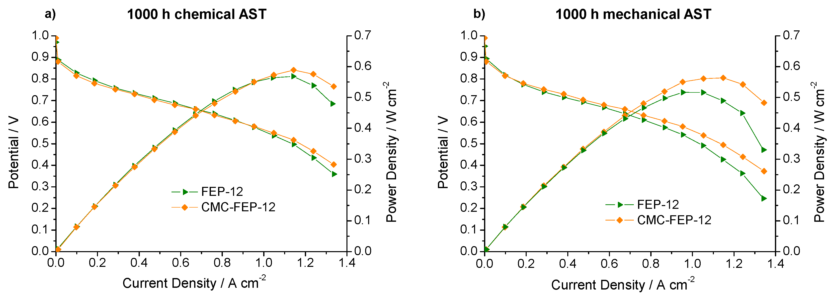
Figure 12 reports polarization and power density curves obtained after 1000 h of both chemical and mechanical AST for FEP-12 and CMC-FEP-12 at 60 °C and RH (A-C) 80–100%.
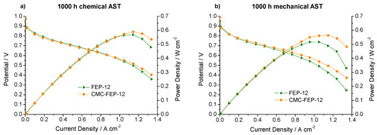
Figure 12.
Polarization and power density curves, obtained upon 1000 h of: chemical (a); and mechanical (b) AST for FEP-12 and CMC-FEP-12 assembled cells.
The surface layer of CMC seems to positively affect the mechanical resistance over the time: since the starting situation is the one of Figure 6a, it can be noticed that CMC-containing sample reacts to external stresses much better than FEP-12, since it shows better performance both after chemical and after mechanical AST. The values of reduction of the maximum output power density (referred to as ∆P) are listed in Table 2.
Table 2.
Variation of output power density upon ASTs.
For each GDM, mechanical AST is more detrimental than chemical one; indeed, it led to the highest losses in power. However, it is evident that the presence of CMC on the surface of MPLs dramatically reduces the degradation of samples: performances after ASTs were very close to those ones obtained for not-damaged GDMs containing CMC.
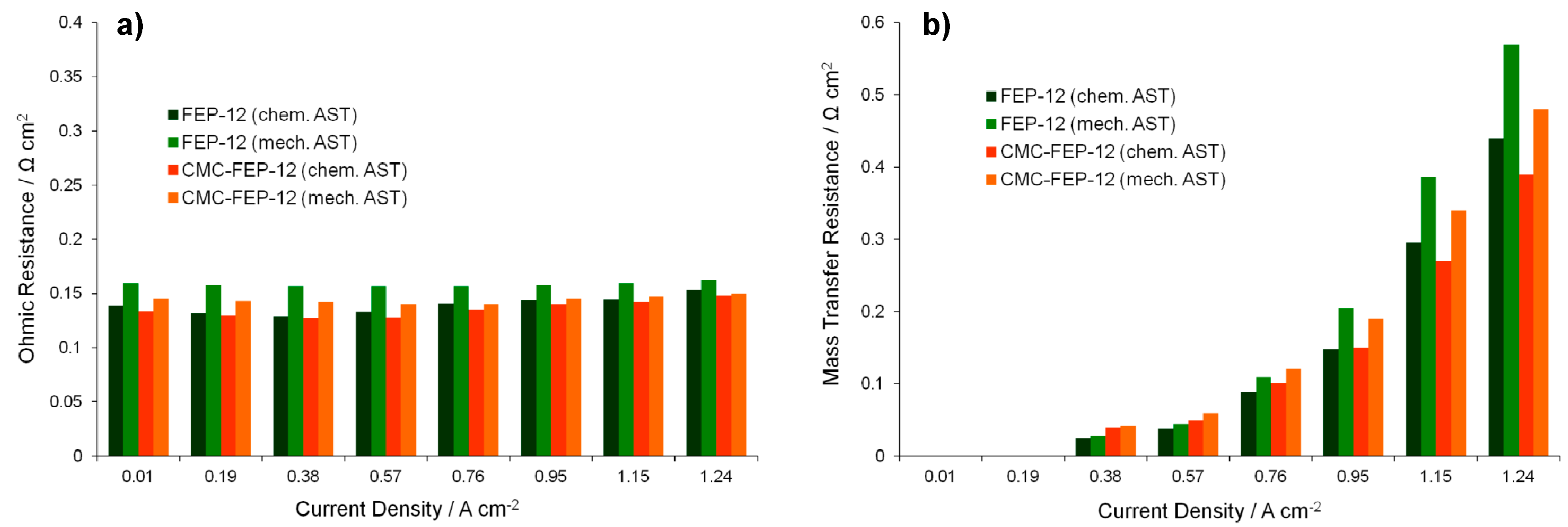
The effects of the stress tests can be even clearer by observing Figure 13 which reports the ohmic and the mass transfer resistances, i.e., the parameters which are mostly influenced by the GDMs features [5], after the total time of stress experiments.
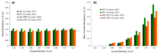
Figure 13.
Ohmic (a); and mass transfer resistances (b) as a function of the current density, obtained with 1000 h chemically and mechanically aged GDMs.
Again, mechanically aged samples, showing higher values of ohmic resistance, are the worst performing GDMs. This graph confirms the benefits which CMC could introduce: GDMs coated with a CMC layer show a lower ohmic resistance after ASTs than FEP-12 samples. This behavior is sharper for mechanically damaged GDMs, as it could have been hypothesized clearly from Figure 12; therefore, the CMC layer probably behaves like a binder which succeeds in reducing damages of GDMs surfaces keeping a good electrical contact between GDL and MEA, thus reducing ohmic resistances increase upon ASTs.
These findings and reasoning occur again when analyzing mass transfer resistance trend of the Figure 13b. The general trend for such parameter was followed: mass transfer resistances started appearing, with very low values, at medium-low current densities (in our cases at 0.38 A cm−2) and then they increased upon increasing current density due to a higher water production.
Diffusion resistance values also proved that the mechanical degradation affects more negatively the device performance than the chemical one. Again, because of the binder effect of the CMC-containing GDMs, such novel components were effective in improving water management at high current densities since lower resistances than samples FEP-12 were found.
This electrochemical behavior could be attributed to a deterioration of physical-chemical features of the GDMs, as it was demonstrated in Reference [5] for FEP-containing GDMs.
Static contact angle measurements (Figure 14) were also performed aiming to assess the effects of ASTs on samples resulting hydrophobicity.
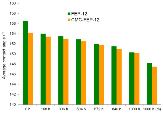
Figure 14.
Progression of the static contact angle over time for the chemically aged GDM, compared with the value measured for the mechanically aged one.
Despite of CMC hydrophilic feature, new GDMs showed a hydrophobicity which was close to that one of FEP-12 samples. Such measurements highlighted a progressive, but not sharp reduction of the hydrophobicity for stressed GDMs. This behavior confirms what was found in authors’ previous work [5] and it is useful to affirm that hydrophobicity is not the main characteristic to be tailored for having a proper water management; an effective adhesion between MPLs and GDLs must be pursued and the surface CMC in these novel GDMs seems to accomplish such target.
4. Conclusions
In this work, different amounts of FEP were used both for GDL and for MPL hydrophobic treatment aiming to optimize GDM composition for having efficient and durable materials.
Ex-situ chemical and mechanical accelerated stress tests (ASTs) were designed and performed to make degradation faster and to evaluate durability of such samples. The highest amount of FEP used in this work (12% by weight) led to achieve the best behavior in terms of hydrophobicity, polarization curve, cell efficiency and mass transport properties. In addition, lower ohmic resistances were obtained for such sample by EIS experiments, both for fresh and for degraded materials.
Then, a CMC layer was applied by spraying coating technique on the surface of the best performing FEP-based MPL to improve adhesion between the MPL and the macro-porous GDL substrate. The presence of CMC reduced overall fuel cell ohmic resistance at low relative humidity due to a better electrolyte hydration.
Chemical and mechanical ASTs showed a better durability for novel CMC-treated samples compared to GDMs containing only FEP, likely due to a binder effect which was introduced by CMC surface molecules. Indeed, such new components were able to dramatically reduce the change, upon ASTs, both in power density and in electrochemical parameters such as ohmic resistance and mass transfer resistance.
Hydrophobicity is reduced upon chemical and mechanical ASTs but still present, therefore it is thought that such feature is not the most important parameter to be optimized for having a satisfying durability but adhesion between MPLs and GDLs and mechanical resistance must be properly addressed and enhanced.
Supplementary Materials
The following are available online at www.mdpi.com/1996-1073/10/12/2063/s1.
Acknowledgments
This work is in memory of Angelo Tronconi who was able to imagine the future.
Author Contributions
Saverio Latorrata and Paola Gallo Stampino conceived and designed the experiments; Saverio Latorrata performed the experiments; Saverio Latorrata, Giovanni Dotelli and Cinzia Cristiani analyzed the data; Cinzia Cristiani and Giovanni Dotelli contributed materials and analysis tools; and Saverio Latorrata and Paola Gallo Stampino wrote the paper.
Conflicts of Interest
The authors declare no conflicts of interest.
References
- Park, S.; Lee, J.W.; Popov, B.N. A review of gas diffusion layer in PEM fuel cells: Materials and designs. Int. J. Hydrogen Energy 2012, 37, 5850–5865. [Google Scholar] [CrossRef]
- Wang, Y.; Chen, K.S.; Mishler, J.; Cho, S.C.; Adroher, X.C. A review of polymer electrolyte membrane fuel cells: Technology, applications, and needs on fundamental research. Appl. Energy 2011, 88, 981–1007. [Google Scholar] [CrossRef]
- Carrette, L.; Friedrich, K.A.; Stimming, U. Fuel Cells—Fundamentals and Applications. Fuel Cells 2001, 1, 5–39. [Google Scholar] [CrossRef]
- Wang, C.; Wang, S.B.; Peng, L.F.; Zhang, J.L.; Shao, Z.G.; Huang, J.; Sun, C.W.; Ouyang, M.G.; He, X.M. Recent Progress on the Key Materials and Components for Proton Exchange Membrane Fuel Cells in Vehicle Applications. Energies 2016, 9, 603. [Google Scholar] [CrossRef]
- Latorrata, S.; Stampino, P.G.; Cristiani, C.; Dotelli, G. Development of an optimal gas diffusion medium for polymer electrolyte membrane fuel cells and assessment of its degradation mechanisms. Int. J. Hydrogen Energy 2015, 40, 14596–14608. [Google Scholar] [CrossRef]
- Barbir, F. PEM Fuel Cells: Theory and Practice; Sustainable World Series; Academic Press: Cambridge, MA, USA, 2005; pp. 1–433. [Google Scholar]
- Katzel, J.; Markotter, H.; Arlt, T.; Klages, M.; Haussmann, J.; Messerschmidt, M.; Kardjilov, N.; Scholta, J.; Banhart, J.; Manke, I. Effect of ageing of gas diffusion layers on the water distribution in flow field channels of polymer electrolyte membrane fuel cells. J. Power Sources 2016, 301, 386–391. [Google Scholar] [CrossRef]
- Ji, M.B.; Wei, Z.D. A Review of Water Management in Polymer Electrolyte Membrane Fuel Cells. Energies 2009, 2, 1057–1106. [Google Scholar] [CrossRef]
- Latorrata, S.; Ponti, F.; Pelosato, R.; Gallo Stampino, P.; Cristiani, C.; Dotelli, G. Development of accelerated stress tests to assess durability of FEP- and carbon nanotubes-based gas diffusion media for PEM fuel cells. In Proceedings of the EMR Conference 2015, Madrid, Spain, 25–27 February 2015; p. 129. [Google Scholar]
- Owejan, J.P.; Trabold, T.A.; Jacobson, D.L.; Arif, M.; Kandlikar, S.G. Effects of flow field and diffusion layer properties on water accumulation in a PEM fuel cell. Int. J. Hydrogen Energy 2007, 32, 4489–4502. [Google Scholar] [CrossRef]
- Mishler, J.; Wang, Y.; Mukundan, R.; Spendelow, J.; Hussey, D.S.; Jacobson, D.L.; Borup, R.L. Probing the water content in polymer electrolyte fuel cells using neutron radiography. Electrochim. Acta 2012, 75, 1–10. [Google Scholar] [CrossRef]
- Ferreira, R.B.; Falcao, D.S.; Oliveira, V.B.; Pinto, A.M.F.R. Experimental study on the membrane electrode assembly of a proton exchange membrane fuel cell: Effects of microporous layer, membrane thickness and gas diffusion layer hydrophobic treatment. Electrochim. Acta 2017, 224, 337–345. [Google Scholar] [CrossRef]
- Antonacci, P.; Chevalier, S.; Lee, J.; Ge, N.; Hinebaugh, J.; Yip, R.; Tabuchi, Y.; Kotaka, T.; Bazylak, A. Balancing mass transport resistance and membrane resistance when tailoring microporous layer thickness for polymer electrolyte membrane fuel cells operating at high current densities. Electrochim. Acta 2016, 188, 888–897. [Google Scholar] [CrossRef]
- Wang, X.L.; Zhang, H.M.; Zhang, J.L.; Xu, H.F.; Tian, Z.Q.; Chen, J.; Zhong, H.X.; Liang, Y.M.; Yi, B.L. Micro-porous layer with composite carbon black for PEM fuel cells. Electrochim. Acta 2006, 51, 4909–4915. [Google Scholar] [CrossRef]
- Wang, Y.; Wang, C.Y.; Chen, K.S. Elucidating differences between carbon paper and carbon cloth in polymer electrolyte fuel cells. Electrochim. Acta 2007, 52, 3965–3975. [Google Scholar] [CrossRef]
- Weber, A.Z.; Darling, R.M.; Newman, J. Modeling two-phase behavior in PEFCs. J. Electrochem. Soc. 2004, 151, A1715–A1727. [Google Scholar] [CrossRef]
- Qi, Z.G.; Kaufman, A. Improvement of water management by a microporous sublayer for PEM fuel cells. J. Power Sources 2002, 109, 38–46. [Google Scholar] [CrossRef]
- Park, S.; Lee, J.W.; Popov, B.N. Effect of PTFE content in microporous layer on water management in PEM fuel cells. J. Power Sources 2008, 177, 457–463. [Google Scholar] [CrossRef]
- Wood, D.; Mukundan, R.; Borup, R. In-Plane Mass-Transport Studies of GDL Variation Using the Segmented Cell Approach. ECS Trans. 2009, 25, 1495–1506. [Google Scholar]
- Antolini, E.; Passos, R.R.; Ticianelli, E.A. Effects of the cathode gas diffusion layer characteristics on the performance of polymer electrolyte fuel cells. J. Appl. Electrochem. 2002, 32, 383–388. [Google Scholar] [CrossRef]
- Giorgi, L.; Antolini, E.; Pozio, A.; Passalacqua, E. Influence of the PTFE content in the diffusion layer of low-Pt loading electrodes for polymer electrolyte fuel cells. Electrochim. Acta 1998, 43, 3675–3680. [Google Scholar] [CrossRef]
- Latorrata, S.; Balzarotti, R.; Stampino, P.G.; Cristiani, C.; Dotelli, G.; Guilizzoni, M. Design of properties and performances of innovative gas diffusion media for polymer electrolyte membrane fuel cells. Prog. Org. Coat. 2015, 78, 517–525. [Google Scholar] [CrossRef]
- Latorrata, S.; Stampino, P.G.; Cristiani, C.; Dotelli, G. Novel superhydrophobic microporous layers for enhanced performance and efficient water management in PEM fuel cells. Int. J. Hydrogen Energy 2014, 39, 5350–5357. [Google Scholar] [CrossRef]
- Yuan, X.Z.; Li, H.; Zhang, S.S.; Martin, J.; Wang, H.J. A review of polymer electrolyte membrane fuel cell durability test protocols. J. Power Sources 2011, 196, 9107–9116. [Google Scholar] [CrossRef]
- Chun, J.H.; Jo, D.H.; Kim, S.G.; Park, S.H.; Lee, C.H.; Kim, S.H. Improvement of the mechanical durability of micro porous layer in a proton exchange membrane fuel cell by elimination of surface cracks. Renew. Energy 2012, 48, 35–41. [Google Scholar] [CrossRef]
- Wu, J.F.; Yuan, X.Z.; Martin, J.J.; Wang, H.J.; Zhang, J.J.; Shen, J.; Wu, S.H.; Merida, W. A review of PEM fuel cell durability: Degradation mechanisms and mitigation strategies. J. Power Sources 2008, 184, 104–119. [Google Scholar] [CrossRef]
- Yousfi-Steiner, N.; Mocoteguy, P.; Candusso, D.; Hissel, D. A review on polymer electrolyte membrane fuel cell catalyst degradation and starvation issues: Causes, consequences and diagnostic for mitigation. J. Power Sources 2009, 194, 130–145. [Google Scholar] [CrossRef]
- Latorrata, S.; Stampino, P.G.; Cristiani, C.; Dotelli, G. Novel Superhydrophobic Gas Diffusion Media for PEM Fuel Cells: Evaluation of Performance and Durability. Chem. Eng. Trans. 2014, 41, 241–246. [Google Scholar]
- Park, S.; Shao, Y.Y.; Viswanathan, V.V.; Liu, J.; Wang, Y. Non-kinetic losses caused by electrochemical carbon corrosion in PEM fuel cells. Int. J. Hydrogen Energy 2012, 37, 8451–8458. [Google Scholar] [CrossRef]
- Wu, B.B.; Zhao, M.; Shi, W.Y.; Liu, W.M.; Liu, J.G.; Xing, D.M.; Yao, Y.F.; Hou, Z.J.; Ming, P.W.; Gu, J.; et al. The degradation study of Nafion/PTFE composite membrane in PEM fuel cell under accelerated stress tests. Int. J. Hydrogen Energy 2014, 39, 14381–14390. [Google Scholar] [CrossRef]
- Zhang, S.S.; Yuan, X.Z.; Wang, H.J.; Merida, W.; Zhu, H.; Shen, J.; Wu, S.H.; Zhang, J.J. A review of accelerated stress tests of MEA durability in PEM fuel cells. Int. J. Hydrogen Energy 2009, 34, 388–404. [Google Scholar] [CrossRef]
- Zhao, M.; Shi, W.Y.; Wu, B.B.; Liu, W.M.; Liu, J.G.; Xing, D.M.; Yao, Y.F.; Hou, Z.J.; Ming, P.W.; Gu, J.; et al. Analysis of carbon-supported platinum through potential cycling and potential-static holding. Int. J. Hydrogen Energy 2014, 39, 13725–13737. [Google Scholar] [CrossRef]
- DOE. Cell Component Accelerated Stress Test Protocols for PEM Fuel Cells. Available online: http://www1.eere.energy.gov/hydrogenandfuelcells (accessed on 23 May 2016).
- D’Urso, C.; Oldani, C.; Baglio, V.; Merlo, L.; Arico, A.S. Towards fuel cell membranes with improved lifetime: Aquivion (R) Perfluorosulfonic Acid membranes containing immobilized radical scavengers. J. Power Sources 2014, 272, 753–758. [Google Scholar] [CrossRef]
- Rodgers, M.P.; Pearman, B.P.; Mohajeri, N.; Bonville, L.J.; Slattery, D.K. Effect of perfluorosulfonic acid membrane equivalent weight on degradation under accelerated stress conditions. Electrochim. Acta 2013, 100, 180–187. [Google Scholar] [CrossRef]
- Kreitmeier, S.; Schuler, G.A.; Wokaun, A.; Buchi, F.N. Investigation of membrane degradation in polymer electrolyte fuel cells using local gas permeation analysis. J. Power Sources 2012, 212, 139–147. [Google Scholar] [CrossRef]
- Park, S.; Shao, Y.Y.; Kou, R.; Viswanathan, V.V.; Towne, S.A.; Rieke, P.C.; Liu, J.; Lin, Y.H.; Wang, Y. Polarization Losses under Accelerated Stress Test Using Multiwalled Carbon Nanotube Supported Pt Catalyst in PEM Fuel Cells. J. Electrochem. Soc. 2011, 158, B297–B302. [Google Scholar] [CrossRef]
- Zhang, J.L.; Song, C.J.; Zhang, J.J. Accelerated Lifetime Testing for Proton Exchange Membrane Fuel Cells Using Extremely High Temperature and Unusually High Load. J. Fuel Cell Sci. Technol. 2011, 8. [Google Scholar] [CrossRef]
- Wu, J.F.; Martin, J.J.; Orfino, F.P.; Wang, H.J.; Legzdins, C.; Yuan, X.Z.; Sun, C. In situ accelerated degradation of gas diffusion layer in proton exchange membrane fuel cell Part I: Effect of elevated temperature and flow rate. J. Power Sources 2010, 195, 1888–1894. [Google Scholar] [CrossRef]
- Wu, J.F.; Yuan, X.Z.; Martin, J.J.; Wang, H.J.; Yang, D.J.; Qiao, J.L.; Ma, J.X. Proton exchange membrane fuel cell degradation under close to open-circuit conditions Part I: In situ diagnosis. J. Power Sources 2010, 195, 1171–1176. [Google Scholar] [CrossRef]
- Shao, Y.Y.; Wang, J.; Kou, R.; Engelhard, M.; Liu, J.; Wang, Y.; Lin, Y.H. The corrosion of PEM fuel cell catalyst supports and its implications for developing durable catalysts. Electrochim. Acta 2009, 54, 3109–3114. [Google Scholar] [CrossRef]
- Lapicque, F.; Belhadj, M.; Bonnet, C.; Pauchet, J.; Thomas, Y. A critical review on gas diffusion micro and macroporous layers degradations for improved membrane fuel cell durability. J. Power Sources 2016, 336, 40–53. [Google Scholar] [CrossRef]
- Ha, T.; Cho, J.; Park, J.; Min, K.; Kim, H.S.; Lee, E.; Jyoung, J.Y. Experimental study on carbon corrosion of the gas diffusion layer in polymer electrolyte membrane fuel cells. Int. J. Hydrogen Energy 2011, 36, 12436–12443. [Google Scholar] [CrossRef]
- Lee, C.; Merida, W. Gas diffusion layer durability under steady-state and freezing conditions. J. Power Sources 2007, 164, 141–153. [Google Scholar] [CrossRef]
- Spernjak, D.; Fairweather, J.; Mukundan, R.; Rockward, T.; Borup, R.L. Influence of the microporous layer on carbon corrosion in the catalyst layer of a polymer electrolyte membrane fuel cell. J. Power Sources 2012, 214, 386–398. [Google Scholar] [CrossRef]
- Yu, S.C.; Li, X.J.; Liu, S.; Hao, J.K.; Shao, Z.G.; Yi, B.L. Study on hydrophobicity loss of the gas diffusion layer in PEMFCs by electrochemical oxidation. Rsc Adv. 2014, 4, 3852–3856. [Google Scholar] [CrossRef]
- Schulze, M.; Wagner, N.; Kaz, T.; Friedrich, K.A. Combined electrochemical and surface analysis investigation of degradation processes in polymer electrolyte membrane fuel cells. Electrochim. Acta 2007, 52, 2328–2336. [Google Scholar] [CrossRef]
- Ha, T.; Cho, J.; Park, J.; Min, K.; Kim, H.S.; Lee, E.; Jyoung, J.Y. Experimental study of the effect of dissolution on the gas diffusion layer in polymer electrolyte membrane fuel cells. Int. J. Hydrogen Energy 2011, 36, 12427–12435. [Google Scholar] [CrossRef]
- Kim, S.; Ahn, B.K.; Mench, M.M. Physical degradation of membrane electrode assemblies undergoing freeze/thaw cycling: Diffusion media effects. J. Power Sources 2008, 179, 140–146. [Google Scholar] [CrossRef]
- Oszcipok, M.; Riemann, D.; Kronenwett, U.; Kreideweis, M.; Zedda, A. Statistic analysis of operational influences on the cold start behaviour of PEM fuel cells. J. Power Sources 2005, 145, 407–415. [Google Scholar] [CrossRef]
- Frisk, J.; Boand, W.; Kurkowski, M.; Atanasoski, R.; Schmoeckel, A. How 3M developed a new GDL construction for improved oxidative stability. In Proceedings of the 2004 Fuel Cell Seminar, San Antonio, TX, USA, 1–5 November 2004. [Google Scholar]
- Wood, D.; Davey, J.; Garzon, F.; Atanassov, P.; Borup, R.L. Mass-transport phenomena and long-term performance limitations in H2-air PEMFC durability testing. In Proceedings of the Fuel Cell Seminar, Palm Springs, CA, USA, 14–18 November 2005. [Google Scholar]
- Latorrata, S.; Stampino, P.G.; Cristiani, C.; Dotelli, G. Preparation, ex situ and in situ Characterization of Gas Diffusion Media Containing and Non-Containing Carboxymethylcellulose for PEM Fuel Cells. Fuel Cells 2015, 15, 463–471. [Google Scholar] [CrossRef]
- Stampino, P.G.; Omati, L.; Cristiani, C.; Dotelli, G. Characterisation of Nanocarbon-Based Gas Diffusion Media by Electrochemical Impedance Spectroscopy. Fuel Cells 2010, 10, 270–277. [Google Scholar] [CrossRef]
- Latorrata, S.; Stampino, P.G.; Amici, E.; Pelosato, R.; Cristiani, C.; Dotelli, G. Effect of rheology controller agent addition to Micro-Porous Layers on PEMFC performances. Solid State Ion. 2012, 216, 73–77. [Google Scholar] [CrossRef]
- Guilizzoni, M.; Stampino, P.G.; Cristiani, C.; Dotelli, G.; Latorrata, S. Formulation and Properties of Different Microporous Layers with Carboxymethylcellulose (CMC) Composition for PEM-FC. Chem. Eng. Trans. 2013, 32, 1657–1662. [Google Scholar]
- Wagner, N. Characterization of membrane electrode assemblies in polymer electrolyte fuel cells using a.c. impedance spectroscopy. J. Appl. Electrochem. 2002, 32, 859–863. [Google Scholar] [CrossRef]
- Boillot, M.; Bonnet, C.; Jatroudakis, N.; Carre, P.; Didierjean, S.; Lapicque, F. Effect of gas dilution on PEM fuel cell performance and impedance response. Fuel Cells 2006, 6, 31–37. [Google Scholar] [CrossRef]
- Barbir, F. PEM Fuel Cells: Theory and Practice; Academic Press: Amsterdam, The Netherlands, 2013; p. 518. [Google Scholar]
- Kim, S.; Jeong, B.H.; Hong, B.K.; Kim, T.S. Effects of hydrophobic agent content in macro-porous substrates on the fracture behavior of the gas diffusion layer for proton exchange membrane fuel cells. J. Power Sources 2014, 270, 342–348. [Google Scholar] [CrossRef]


© 2017 by the authors. Licensee MDPI, Basel, Switzerland. This article is an open access article distributed under the terms and conditions of the Creative Commons Attribution (CC BY) license (http://creativecommons.org/licenses/by/4.0/).