Design and Selection of Innovative Primary Circulation Pumps for GEN-IV Lead Fast Reactors

 ,
,  ,
,
Abstract
:1. Introduction
2. Background
2.1. Lead as Liquid Metal Coolant for Fast Reactor
- LFR can, in principle, operate at higher temperature than SFR, increasing thermal efficiency and ensuring a substantially higher safety margin
- Primary system pressurization is not necessary, as it must be done in the case of water; safety of the system is improved as the probability of loss of coolant accident is practically eliminated.
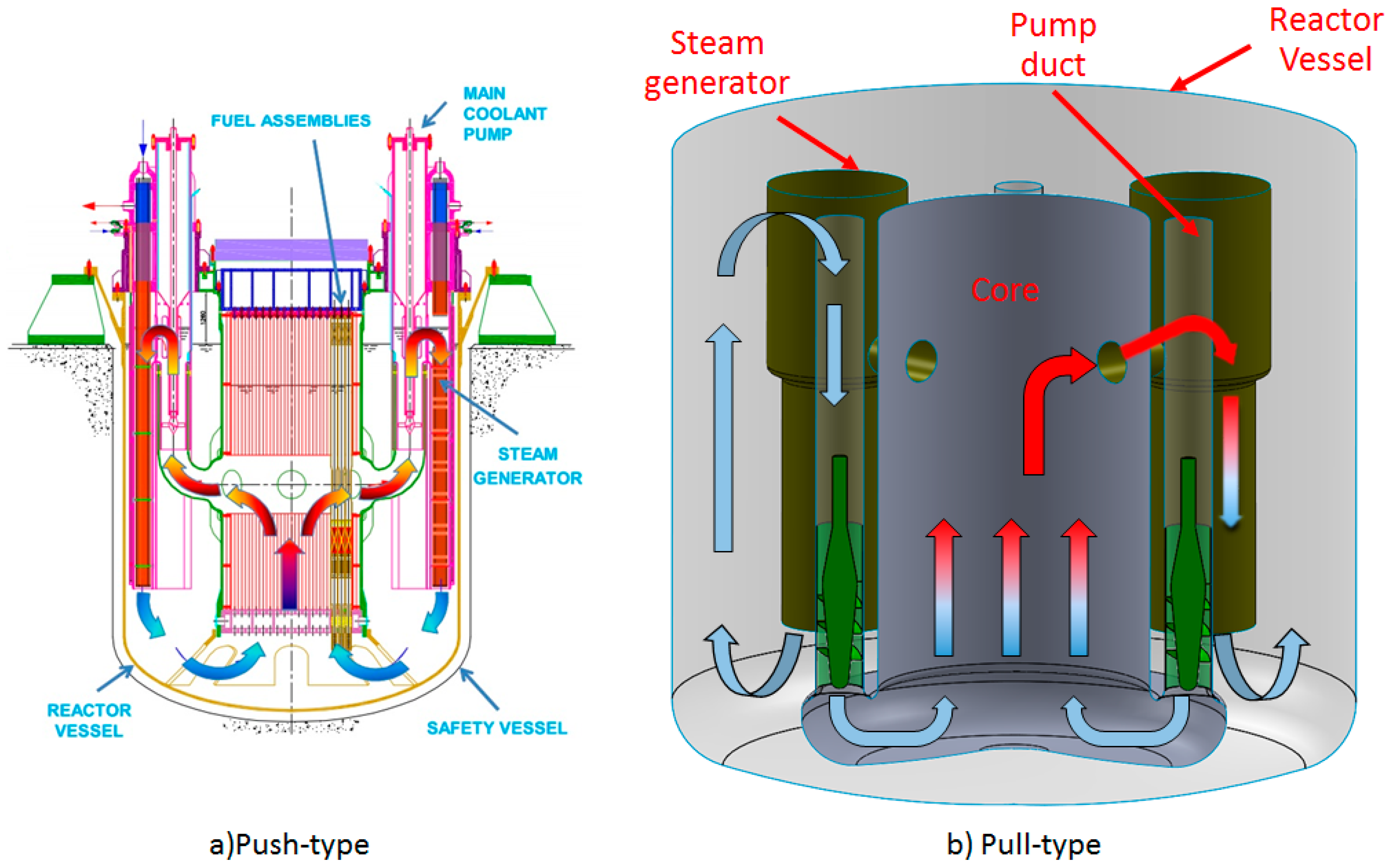
- It does not react with air and water, therefore the intermediate loop can be removed, and the steam generators can be installed directly within the Reactor Vessel (RV). In case of coolant losses, the requirements will be less stringent
- Very high boiling point, hence the presence of voids or core uncover are reduced
- Density greater than the fuel, therefore, a core catcher is not required to deal with a core melting accident: there is no risk of return to criticality after meltdown
- Low absorption cross section and low moderating power, therefore a very compact fuel assembly is not necessary, then the passage section in the fuel assembly is large enough to maintain a low speed, low pressure drop, reduce pumping power and to obtain a large capacity to sustain NC.
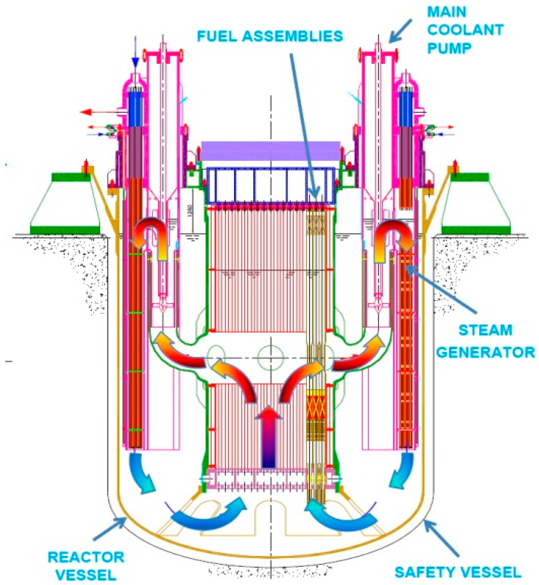
2.2. ALFRED (Advanced Lead Fast Reactor European Demonstrator)
3. Results
- (a)
- The minimization of maximum velocity on the blade or in the neck section: at the driver tip for jet pump and on the peripheral sections or at the tip of the blade in the crew and semi-axial configurations
- (b)
- The minimization of the pressure loss at pump off in locked rotor conditions: this is considered a very important requirement to allow the establishment of the natural circulation; for some configurations (like the jet pump) the issue is solved at design level but, for the screw and the blade pump, a particular design of the blade and an accurate sizing of the inlet and outlet section is required to minimize pressure losses in natural circulation.
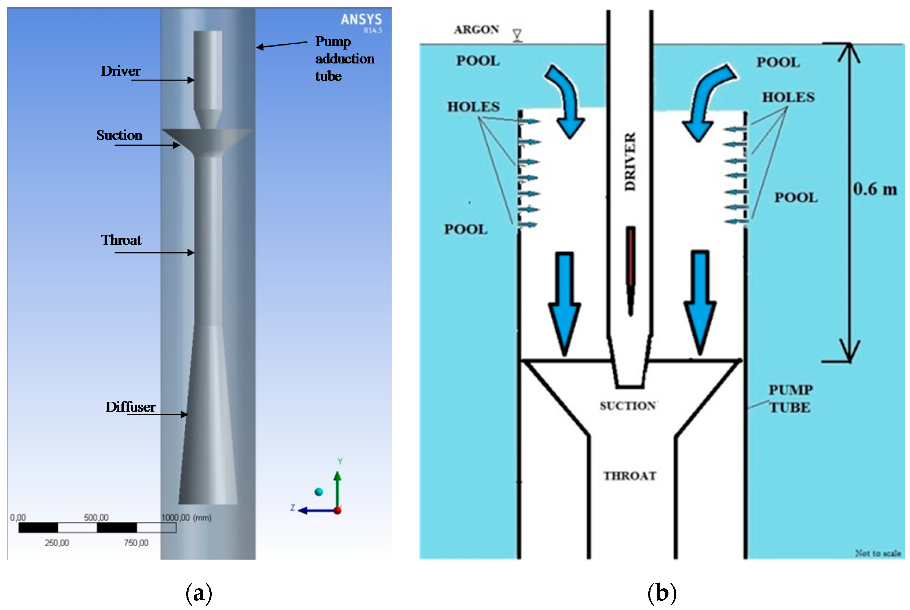
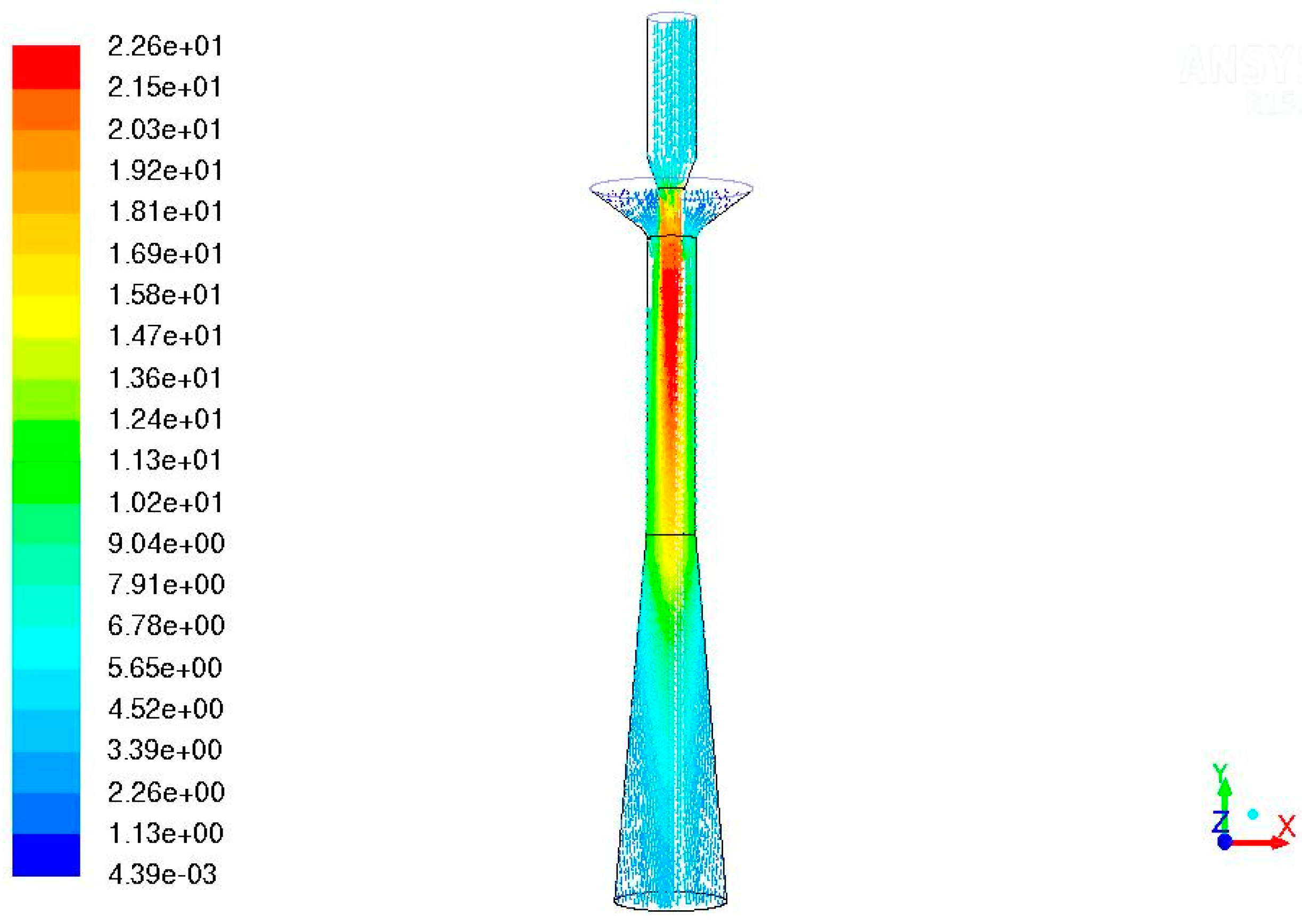
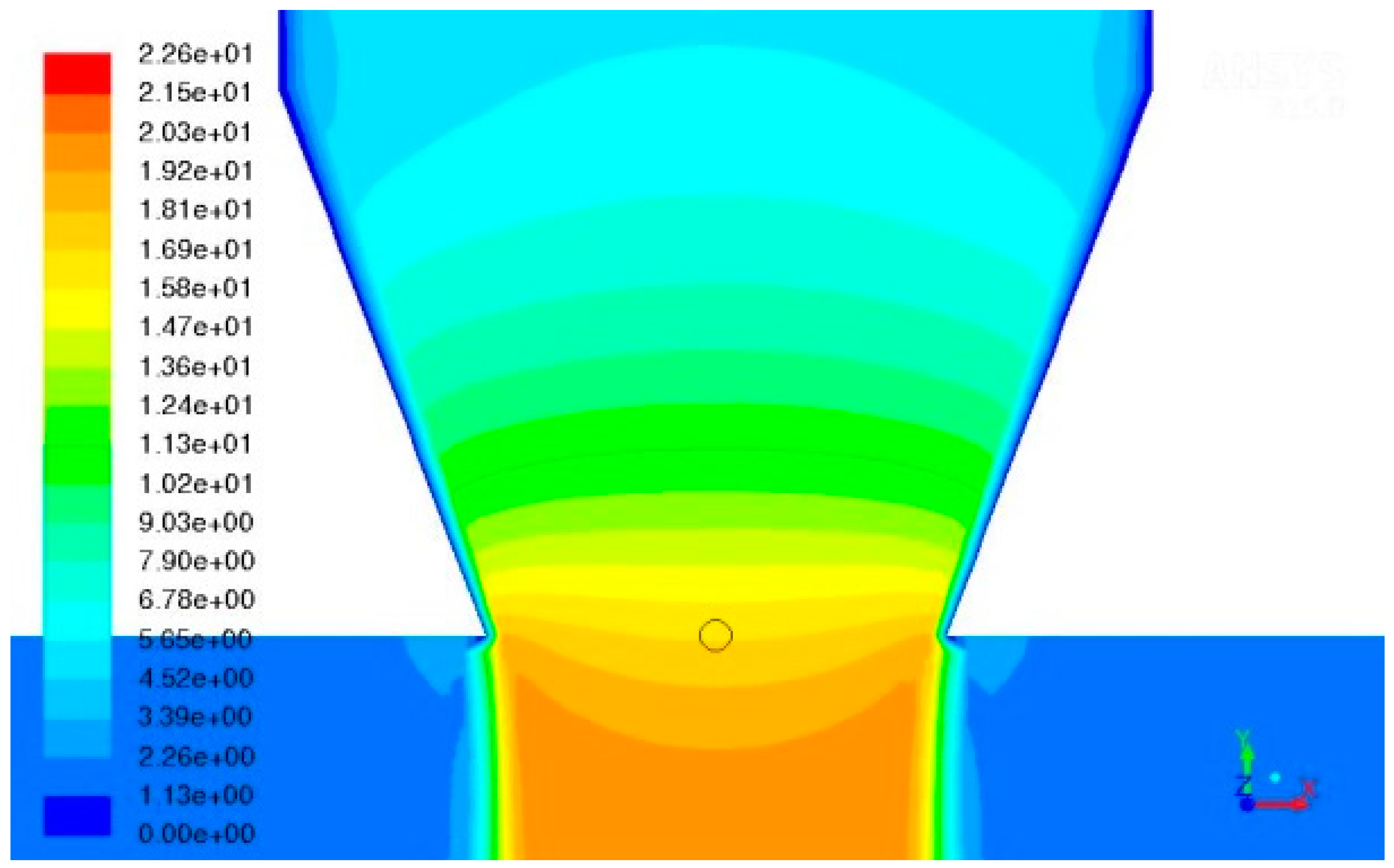
3.1. Theoretical and CFD Simulation of the Jet Pump
- The pump is placed inside the pump tube, which has a diameter of 0.6 m and a longitudinal length of 8 m
- The pump operates with lead entering the tube at 400 °C from the top, near the free surface of the pool, and/or from holes in the upper part of the tube
- The pressure at inlet and outlet are affected by the hydrostatic head
- The pump must ensure a head of at least 1.5 bar to provide the required coolant circulation and compensate the pressure losses in the circuit
- The volumetric mass flow rate must be 0.31 m3/s (3274 kg/s) at each pump
- Proper provisions shall be applied to minimize the pressure loss at NC conditions.
- The inlet mass flow rate at suction: this parameter has been evaluated until it remains constant
- The convergence of the residuals, evaluating the residuals trend during the simulation: it is considered acceptable a convergence of at least 1.0 × 10⁻⁵.
- The liquid lead velocity of 15 m/s at the driver’s tip. While present technology supplies various surface treatments to deal with the erosion phenomena caused by lead, the long-term sustainability of a jet pump working with a driver requiring a maximum velocity of 15 m/s is at least questionable. It is not currently possible to give assurance that this device could respect the durability in these conditions without structural damages
- An operative pressure of at least 23 bar for the driver. The authors are not aware of any general-purpose or especially engineered pump elaborating liquid lead and producing such a pressure. Possibly, the design of such a pump is of the same order of technological difficulty as the jet pump it is supposed to drive.
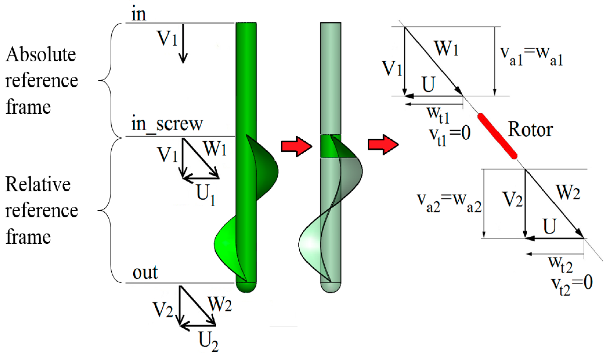
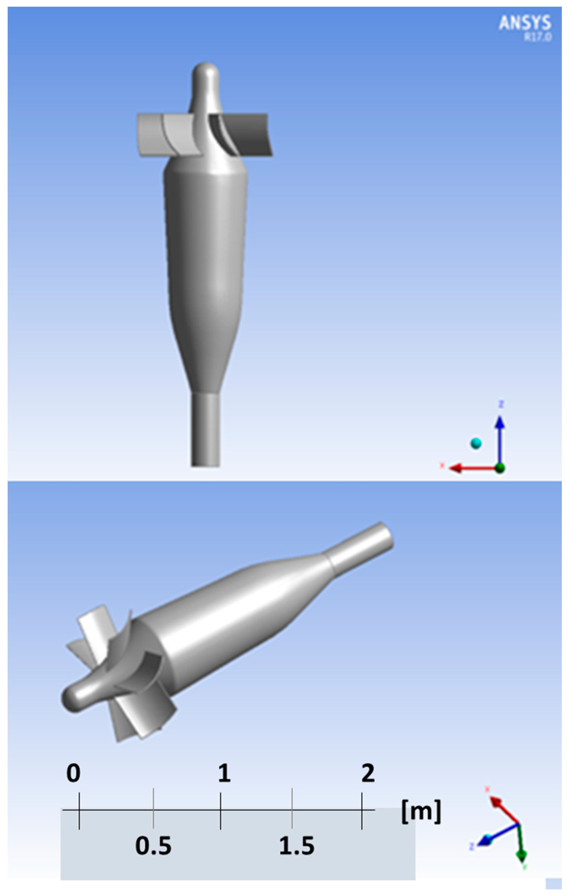
3.2. Theoretical and CFD Simulation of the Archimedean Pump
- Enabling the coolant NC in accidental or only locked rotor conditions
- Removing the heat from the core even in the case of failure of any (Design Basis Scenario) or all (Station Black-out Scenario) of the eight pumps.
- Rotational speed: the velocity inside the pump shall not exceed 10 m/s, due to erosion phenomena
- Pump duct’s diameter: the diameter shall be smaller than 1.2 m, to limit the diameter of the vessel, that contain each component
- Duct’s pump length: about 5 m from the pool’s free surface to the location of the impeller, due to safety requirements in terms of possible entrainment of gas in the flow, which in the case this gas reaches the core it could produce unexpected positive reactivity peak.
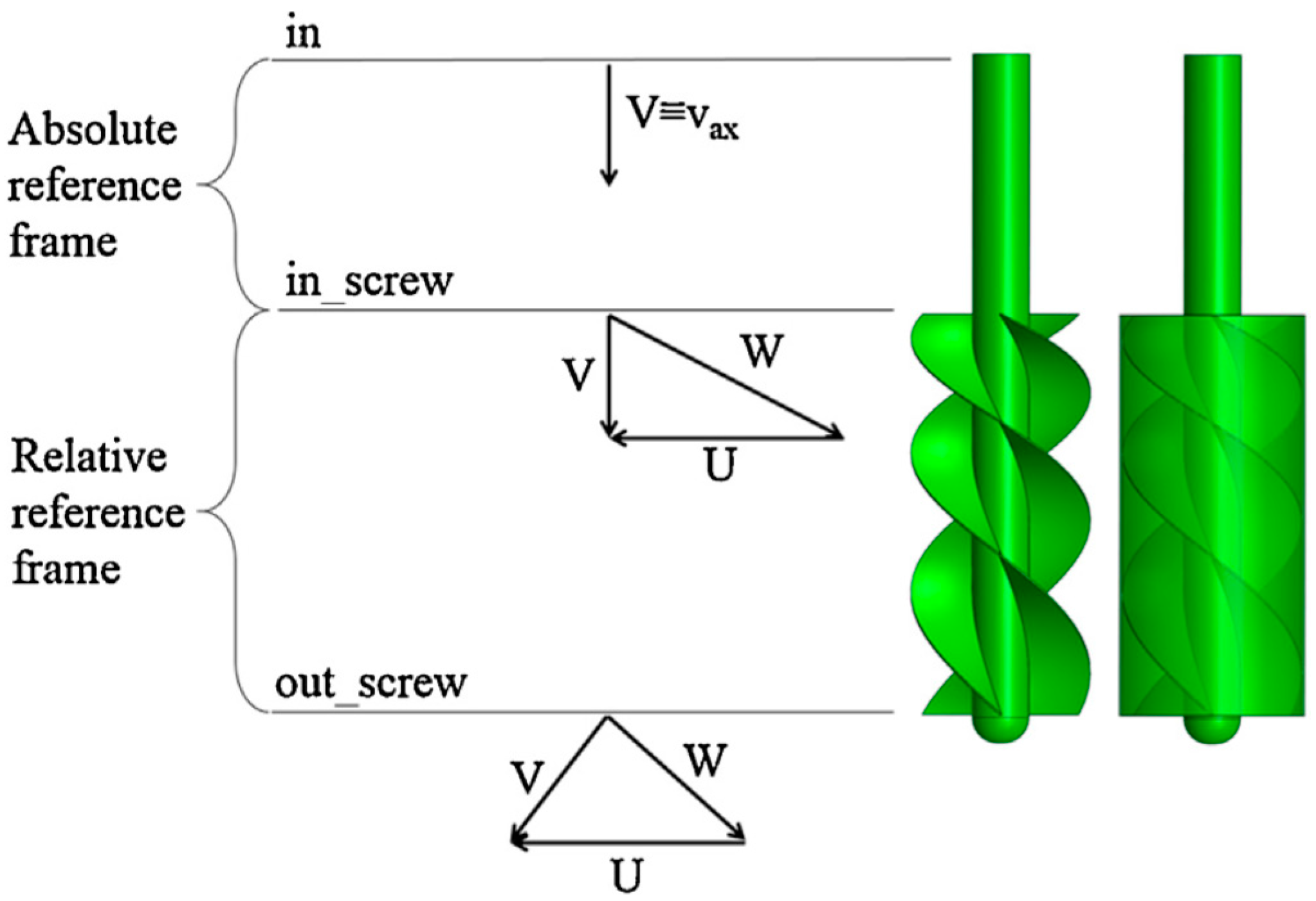
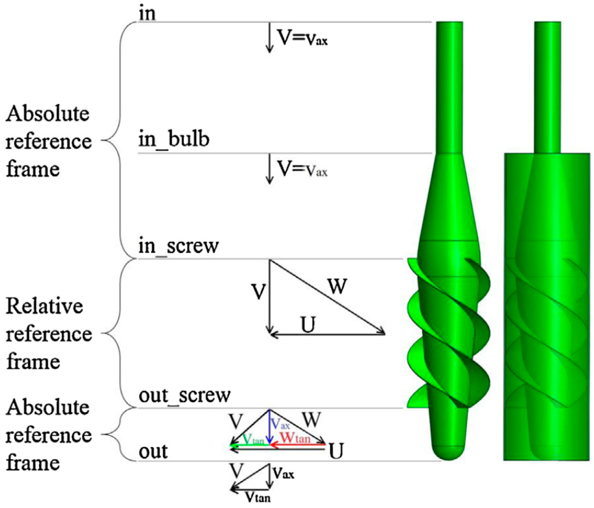
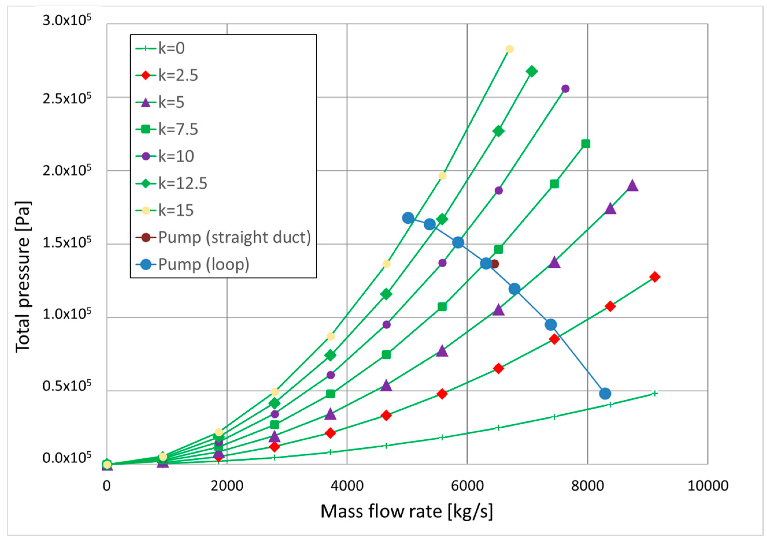
- By deflecting the flow via a change of the hub diameter of the screw pump (Figure 9). Doing so, the flow increases its absolute velocity moving from the section in bulb to the section in screw. Then, according to the canonical equations [19], the static pressure decreases in this portion of the pump, although passing from the section in screw to the section out screw the static pressure increases more than the previous decrease. So, this Archimedean pump with variable hub diameter can generate the required increase of pressure.
- f = Darcy friction factor
- L/D = geometrical loop sizes
- Kcurv = concentrated pressure losses coefficient of the curves
- Kpj = concentrated pressure losses coefficient of porous jump (pressure jump coefficient).
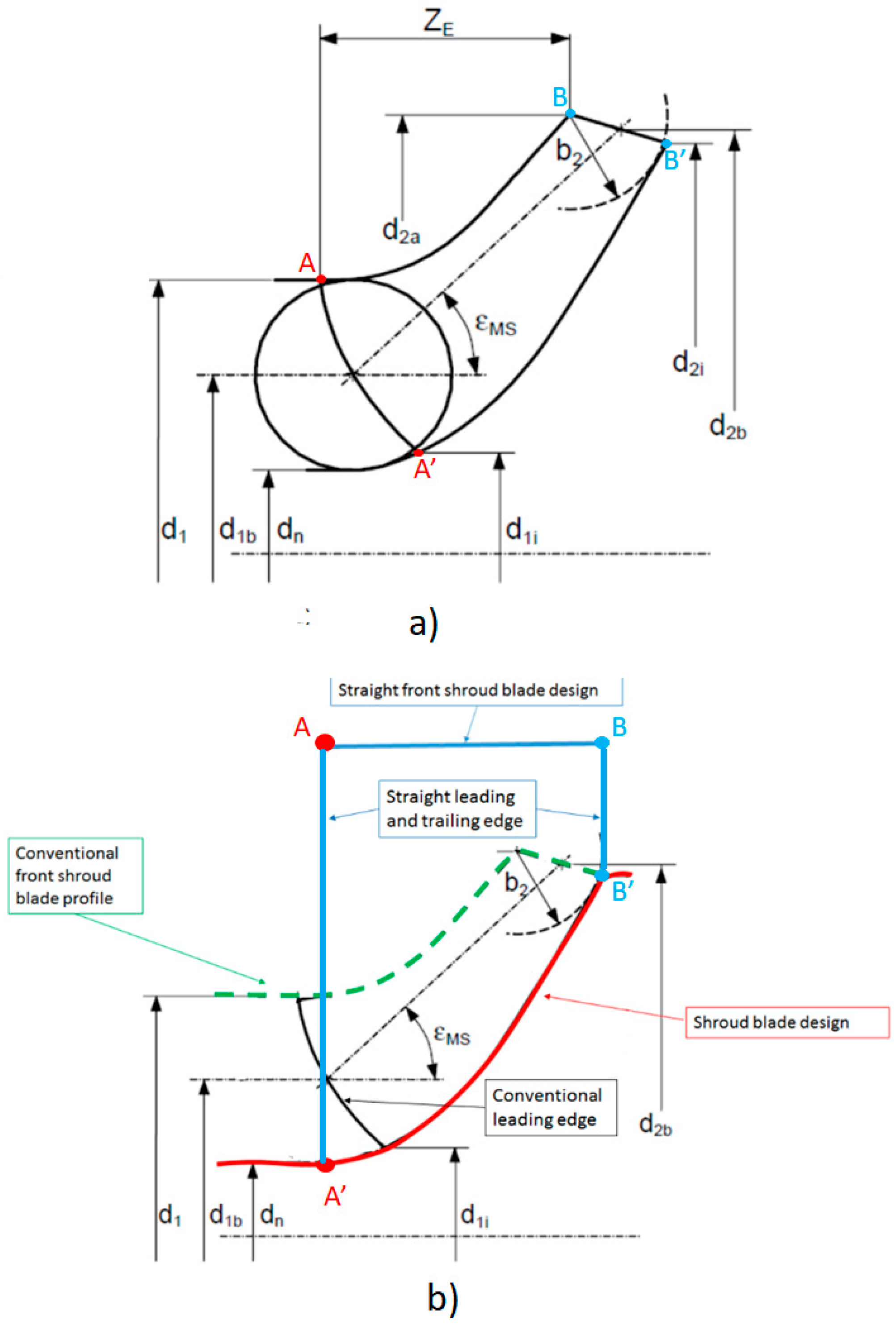
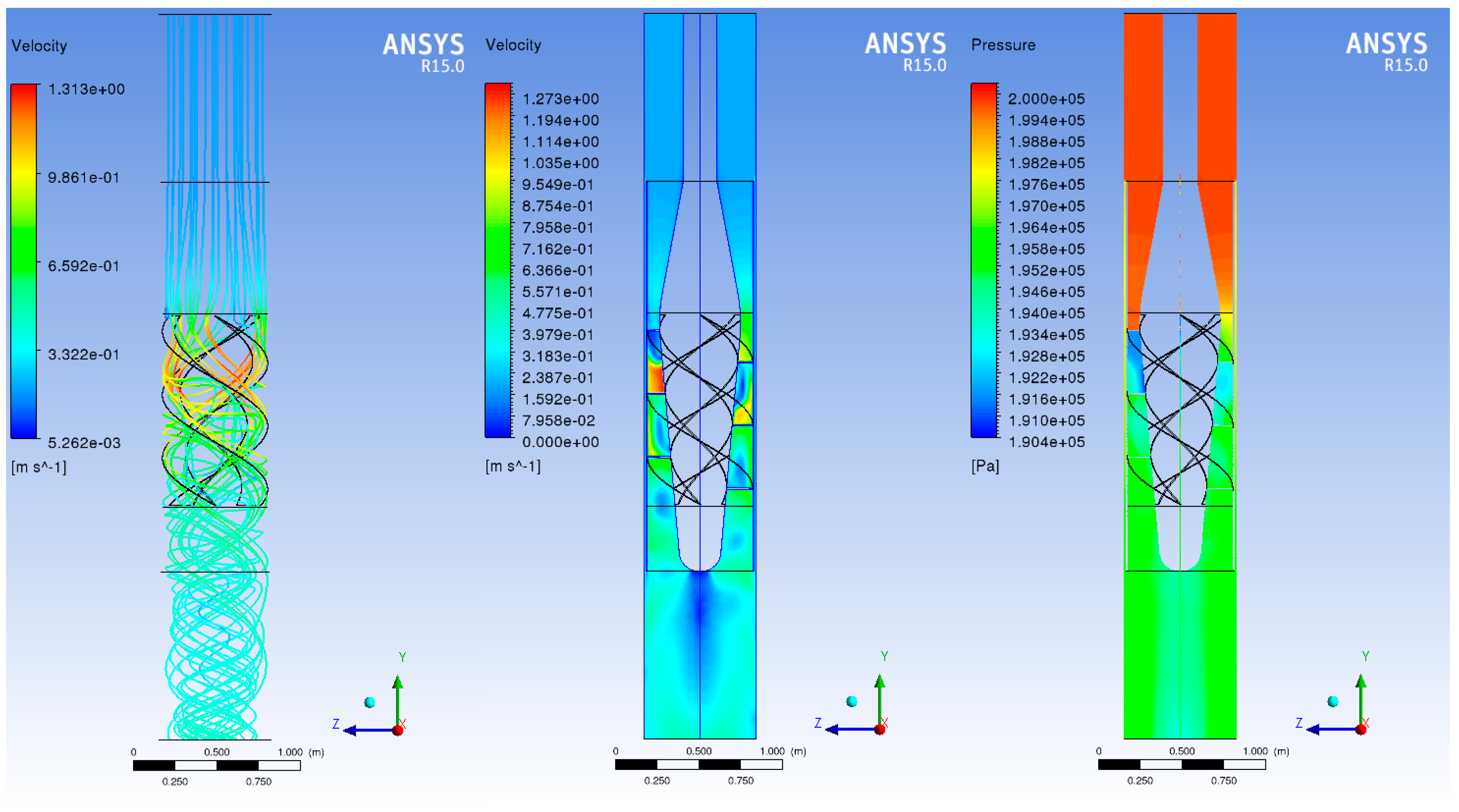
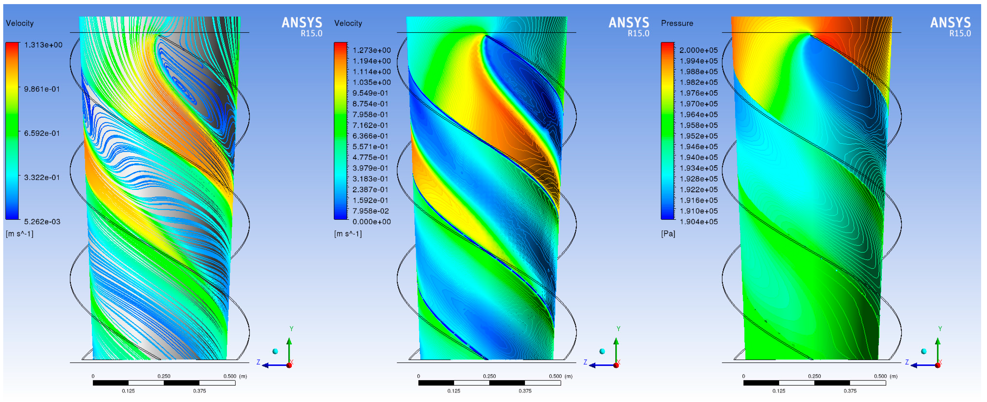
3.3. Theoretical and CFD Simulation of the Blade Pump
- The largest section at the inlet (A-A’ arc of Figure 16a) vs. segment A-A’ of Figure 16b and the outlet (B-B’ segment of Figure 16a) vs. segment B-B’ of Figure 16b section: this reduces the velocity of the flow, the consequent corrosion phenomena and structural load that are due to the high specific weight of the molten lead
- The straight trailing and leading edge: the high inertia of the molten lead flow makes negligible the smallest scale geometry details (like high curvature elements or small fillet) regarding flow deviations.
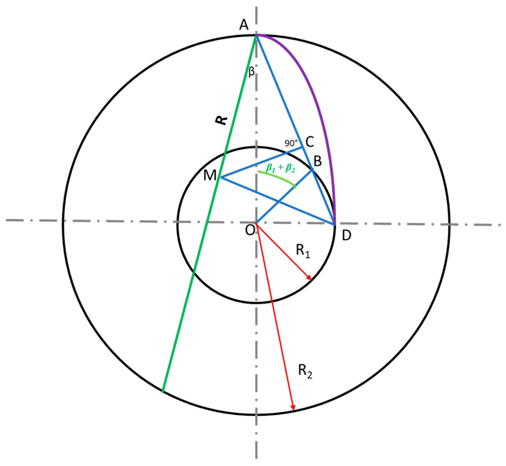
- To construct vane profile
- To draw a single radius circular arc using the calculated angle β1, β2 and radii R1, R2.
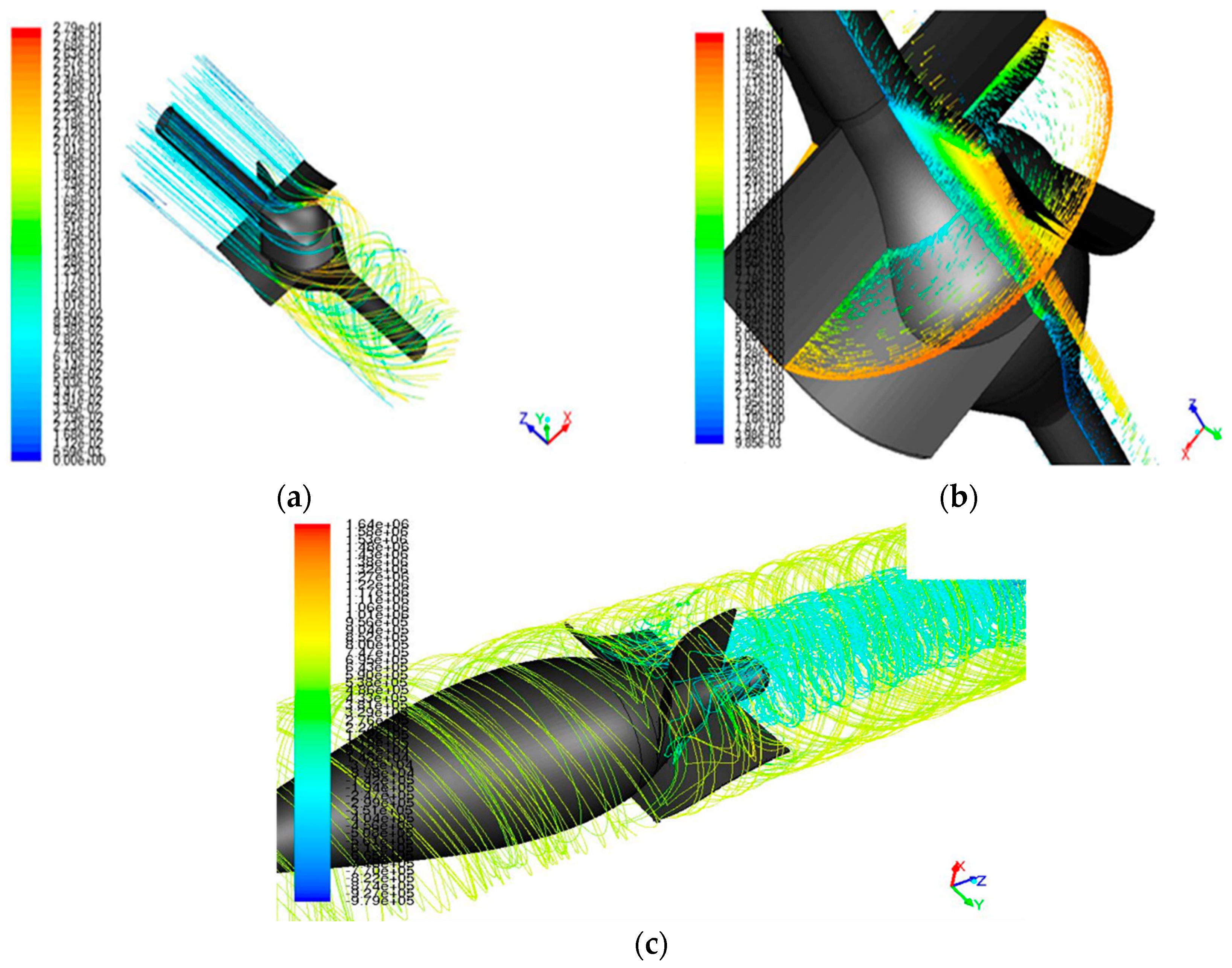
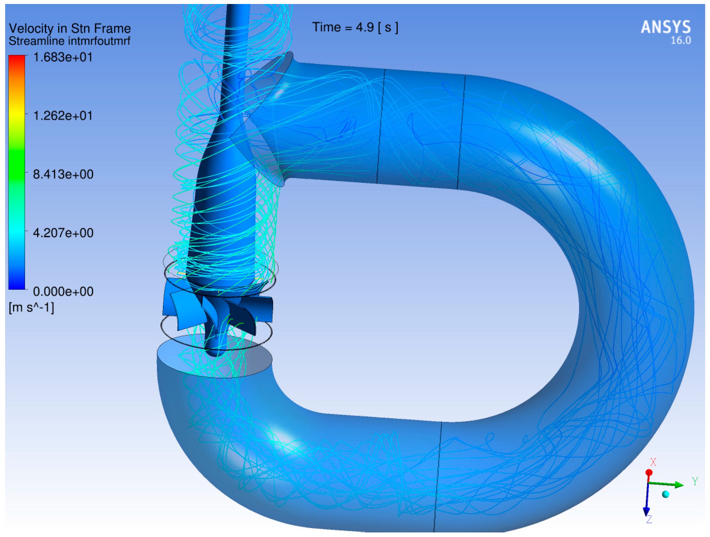
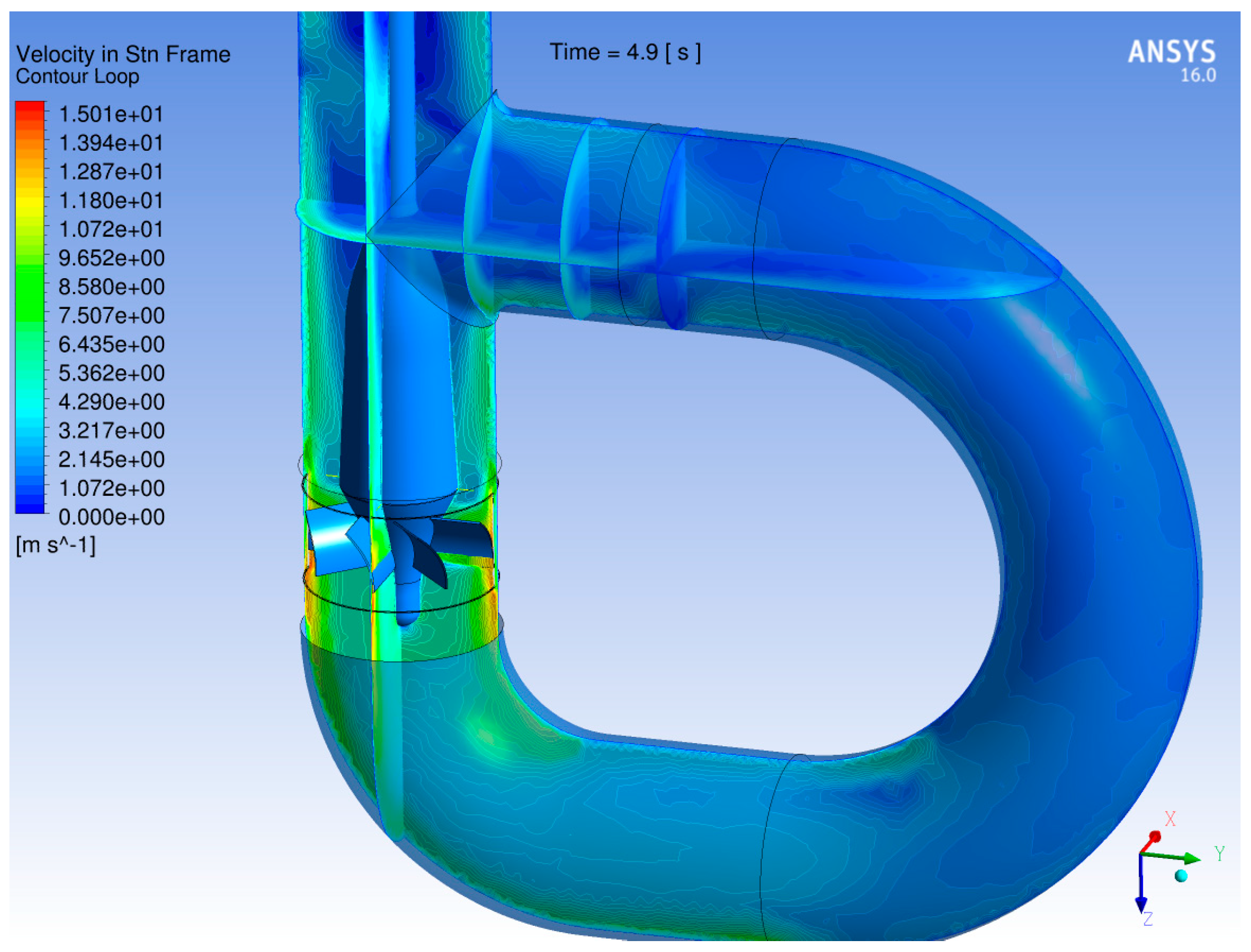
- The flow leaving the rotor (at the pump’s outlet) is swirled and in correspondence of the T-junction results in a very “chaotic” velocity field. Consequently, the flow entering the steam generator is very irregular with potential problems of uneven coverage of the tube bundle, different thermal loads on the tube bundle and intermittent flow
- The pre-rotation imposed by the impeller to the incoming flow may propagate to the flow leaving the core
4. Discussion
- Jet Pump
- ○
- The liquid lead velocity at the driver’s tip is beyond the current technology for sustained operations
- ○
- The pressure required for the driver is beyond the current technology for sustained operations
- Archimedean (screw) Pump
- ○
- The mechanical connection of the screw to the hub requires welding, a processing technique presenting a number of challenges when applied in flowing liquid lead
- ○
- The self-centering of the pump’s beam inside the duct presents significant mechanical challenges
- Blade Pump
- ○
- The flow downstream the pump presents a significant swirling component
- ○
- The pre-rotation of the flow upstream of the rotor may impact on the flow field exiting from the core
5. Materials and Methods
5.1. General Considerations and CFD Analysis of Selected Pumps
- Mass flow rate = 6450 kg/s = 2200 m3/h
- Pump differential pressure = 1.5 bar ( head = 1.48 m).
- Generate the design mass flow rate and differential pressure keeping the minimum velocity inside the pump to limit erosion phenomena
- Minimize the flow resistance, when the pumps is non-rotating, to reduce the obstacles for the onset of NC of the fluid in accidental situation
- Have a self-centering effect inside th pump duct to overcome the absence of a bearing under the pump.
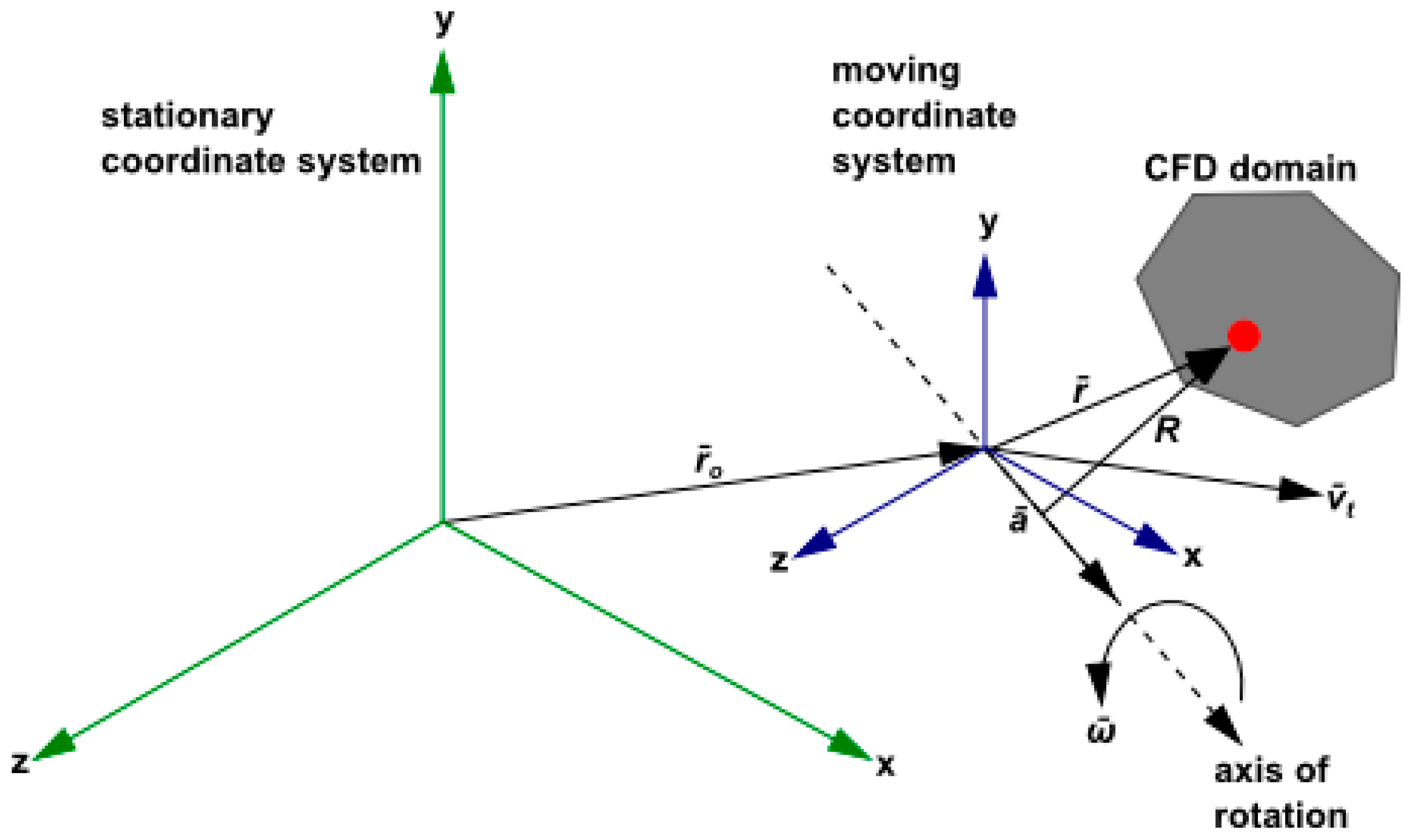
5.2. A Short Introduction to the CFD Model Developed and Multiple Reference Frame CFD Model Approach for Rotating Frame
- Expressing the momentum equations using the relative velocities as dependent variables (known as the relative velocity formulation)
- Expressing the momentum equations using the absolute velocities as dependent variables in the momentum equations (known as the absolute velocity formulation).
- Conservation of mass:
- Conservation of momentum:
- Conservation of energy:
6. Conclusions
Acknowledgments
Author Contributions
Conflicts of Interest
References
- Castelliti, D.; Lomonaco, G. A preliminary stability analysis of MYRRHA primary heat exchanger two-phase tube bundle. Nucl. Eng. Des. 2016, 305, 179–190. [Google Scholar] [CrossRef]
- Borreani, W.; Bruzzone, M.; Chersola, D.; Firpo, G.; Lomonaco, G.; Palmero, M.; Panza, F.; Ripani, M.; Saracco, P.; Viberti, C.M. Preliminary thermal-fluid-dynamic assessment of an ADS irradiation facility for fast and slow neutrons. Int. J. Heat Technol. 2017, 35, S186–S190. [Google Scholar] [CrossRef]
- Panza, F.; Firpo, G.; Lomonaco, G.; Osipenko, M.; Ricco, G.; Ripani, M.; Saracco, P.; Viberti, C.M. New infrastructure for studies of transmutation and fast systems concepts. EPJ Web Conf. 2017, 153, 05003. [Google Scholar] [CrossRef]
- Lomonaco, G.; Borreani, W.; Bruzzone, M.; Chersola, D.; Firpo, G.; Palmero, M.; Panza, F.; Ripani, M.; Saracco, P.; Viberti, C.M. Initial thermal-hydraulic assessment by OpenFOAM and FLUENT of a subcritical irradiation facility. Therm. Sci. Eng. Prog. 2017. under review. [Google Scholar]
- International Atomic Energy Agency (IAEA). Nuclear Power Reactors in the World; Reference Series No. 2; IAEA: Vienna, Austria, 2013. [Google Scholar]
- Alemberti, A.; Lomonaco, G.; Borreani, W.; Magugliani, F. Theoretical and numerical investigation of three designs for a primary circulation pump evolving liquid lead for GEN-IV reactors. In Proceedings of the IV ISTC NIKIET “Innovative Designs and Technologies of Nuclear Power”, Moscow, Russia, 27–30 September 2016. [Google Scholar]
- Cerullo, N.; Lomonaco, G. Generation IV reactor designs, operation and fuel cycle. In Nuclear Fuel Cycle Science and Engineering; Crossland, I., Ed.; Woodhead Publishing: Cambridge, UK, 2012; pp. 333–395. [Google Scholar] [CrossRef]
- Nuclear Energy Agency. Handbook on Lead-Bismuth Eutectic Alloy and Lead Properties, Materials Compatibility, Thermal-Hydraulics and Technologies; Nuclear Energy Agency: Boulogne-Billancourt, France, 2015; Available online: https://www.oecd-nea.org/science/pubs/2015/7268-lead-bismuth-2015.pdf (accessed on 30 September 2017).
- Menter, F.R. Zonal two equation k-ω Turbulence models for aerodynamic flows. In Proceedings of the 23rd Fluid Dynamics, Plasmadynamics, and Lasers Conference, Orlando, FL, USA, 6–9 July 1993. AIAA Paper 93-2906. [Google Scholar]
- Tennekes, H.; Lumley, J.L. A First Course in Turbulence, 1st ed.; MIT Press: Cambridge, MA, USA, 1972; ISBN 9780262200196. [Google Scholar]
- Hirsch, C. Numerical Computation of Internal and External Flows: The Fundamentals of Computational Fluid Dynamics, 2nd ed.; Butterworth-Heinemann: Oxford, UK, 2007; ISBN 9780750665940. [Google Scholar]
- Borreani, W. Thermo-Hydraulic Analysis by Different CFD Codes of Some Components of the Primary System of Gen-IV Lead-Cooled Demonstrator ALFRED. Ph.D. Thesis, University of Genova, Genoa, Italy, 2017. [Google Scholar]
- ANSYS. Available online: http://www.ansys.com/Products/Fluids/ (accessed on 30 September 2017).
- The RELAP5-3D Code Development Team. RELAP5-3D© Code Manual Volume I: Code Structure, System Models and Solution Methods; INEEL-EXT-98-00834, Revision 2.3; Idaho National Laboratory: Idaho Falls, ID, USA, 2005.
- Mangialardo, A.; Borreani, W.; Lomonaco, G.; Magugliani, F. Numerical investigation on a jet pump evolving liquid lead for GEN-IV reactors. Nucl. Eng. Des. 2014, 280, 608–618. [Google Scholar] [CrossRef]
- Cunningham, R.G. Jet pump theory. In Pump Handbook, 3rd ed.; Karassik, I.J., Messina, J.P., Cooper, P., Heald, C.C., Eds.; McGraw-Hill: New York, NY, USA, 2007. [Google Scholar]
- El-Sawaf, I.A.; Halawa, M.A.; Younes, M.A.; Teaima, I.R. Study of the different parameters that influence on the performance of water jet pump. In Proceedings of the 15th International Water Technology Conference (IWTC 15), Alexandria, Egypt, 31 March–2 April 2011. [Google Scholar]
- Lizzoli, M.; Borreani, W.; Devia, F.; Lomonaco, G.; Tarantino, M. Preliminary CFD assessment of an experimental test facility operating with heavy liquid metals. Sci. Technol. Nucl. Install. 2017, 2017, 1949673. [Google Scholar] [CrossRef]
- Ferrini, M.; Borreani, W.; Lomonaco, G.; Magugliani, F. Design by theoretical and CFD analyses of a multi-blade screw pump evolving liquid lead for a Generation IV LFR. Nucl. Eng. Des. 2016, 297, 276–290. [Google Scholar] [CrossRef]
- Gülich, J.F. Centrifugal Pumps, 3rd ed.; Springer: Berlin, Germany, 2014. [Google Scholar]
- Sahu, G.K. Pumps; New Age International Ltd.: New Delhi, India, 2005; ISBN 81-224-1224-6. [Google Scholar]
- Srinivasan, K.M. Rotodynamic Pumps (Centrifugal and Axial); New Age International: New Delhi, India, 2008. [Google Scholar]
- Nesbitt, B. Handbook of Pumps and Pumping; Elsevier: Amsterdam, The Netherlands, 2006; ISBN 9781856174763. [Google Scholar]


| Coolant | H2O (155 bar, 573 K) | Na (1 bar, 673 K) | Pb (1 bar, 673 K) | |
|---|---|---|---|---|
| Proprieties | ||||
| Density (kg/m3) | 727 | 856 | 10563 | |
| Tmelting (K) | - | 371 | 601 | |
| Tboiling (K) | 618 | 1156 | 2023 | |
| Heat capacity (J/(m3·K)) | 3.9 × 10⁶ | 1.1 × 10⁶ | 1.5 × 10⁶ | |
| Dynamic viscosity (Pa·s) | 0.09 × 10⁻³ | 0.28 × 10⁻³ | 2.23 × 10⁻³ | |
| Thermal Conductivity (W/mK) | 0.6 | 72 | 17 | |
| Vapor pressure (Pa) | 8.6 × 10⁶ | 52 | 2.8 × 10⁻⁵ | |
| Parameter | Value |
|---|---|
| Power | 300 MWth |
| Primary coolant | Lead |
| Primary system | Pool type, compact |
| Primary side lead temperature | 400 ÷ 480 °C |
| Primary coolant circulation (at power) | Forced (mechanical pumps) |
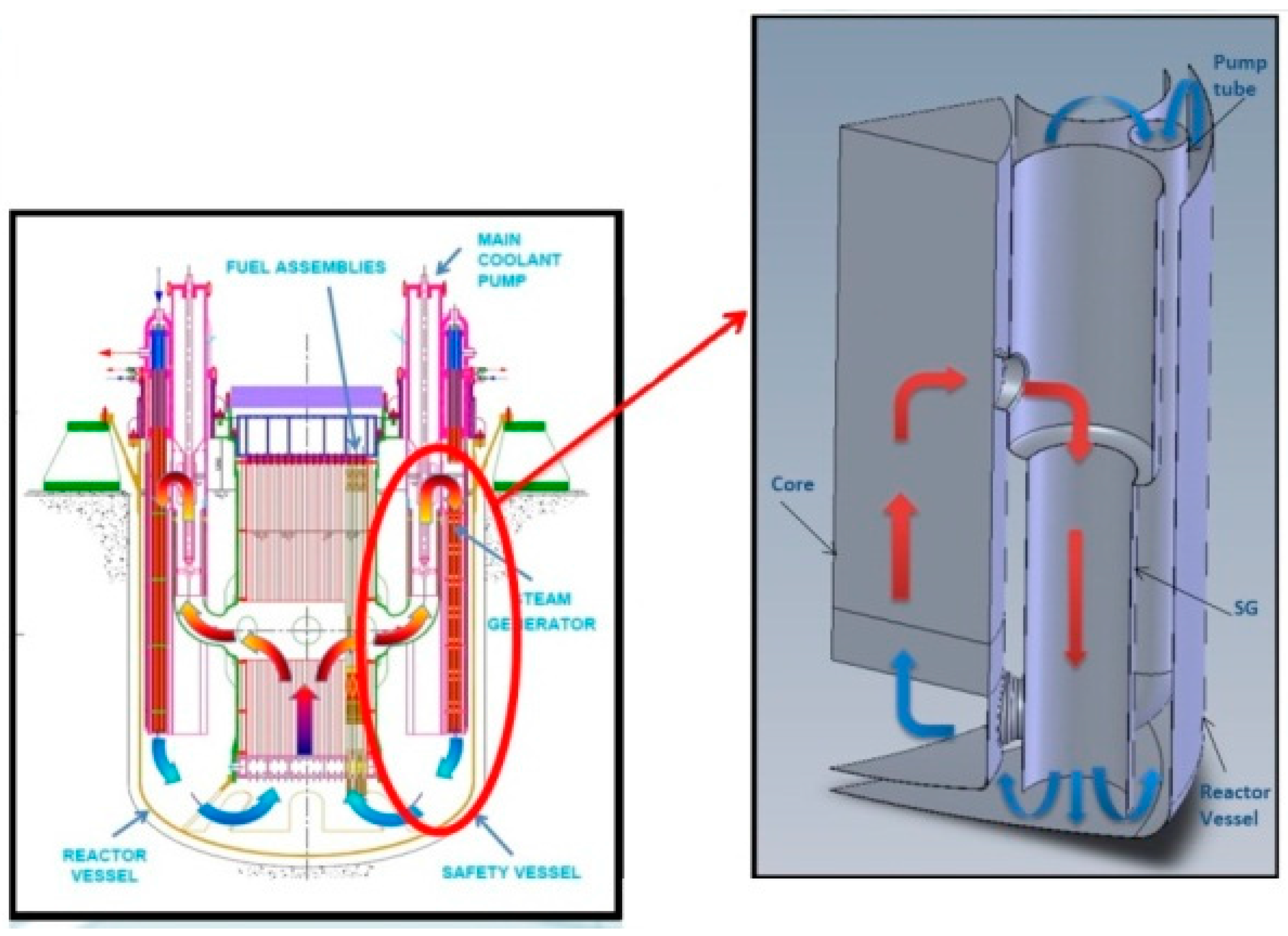
| Primary pump | 8, mechanical, removable, located in hot leg inside the inner vessel |
| Steam generator | 8, once-through, removable, integrated in the main vessel |
| Secondary cycle | Water superheated steam at 180 bar, 335 ÷ 450 °C |
| Decay heat removal | 2, independent, redundant and diverse DHR systems |
| Overall efficiency | 40% (or higher) |
| Internals | All internals removable |
| Density (kg/m3) | ρ = 11441 − 1.2795 × T |
| Dynamic viscosity (Pa·s) | µ = 4.55 × 10⁻⁴ × e(1069/T) |
| Case | (kg/s) | (kg/s) | M | N | Ptotsuction (bar) | Ptotdriver (bar) |
|---|---|---|---|---|---|---|
| Reference case | 2202 | 1250 | 1.76 | 0.229 | 1.63 | 26.3 |
| Optimal case | 2010 | 1310 | 1.53 | 0.28 | 1.63 | 23 |
© 2017 by the authors. Licensee MDPI, Basel, Switzerland. This article is an open access article distributed under the terms and conditions of the Creative Commons Attribution (CC BY) license (http://creativecommons.org/licenses/by/4.0/).
Share and Cite
Borreani, W.; Alemberti, A.; Lomonaco, G.; Magugliani, F.; Saracco, P. Design and Selection of Innovative Primary Circulation Pumps for GEN-IV Lead Fast Reactors. Energies 2017, 10, 2079. https://doi.org/10.3390/en10122079
Borreani W, Alemberti A, Lomonaco G, Magugliani F, Saracco P. Design and Selection of Innovative Primary Circulation Pumps for GEN-IV Lead Fast Reactors. Energies. 2017; 10(12):2079. https://doi.org/10.3390/en10122079
Chicago/Turabian StyleBorreani, Walter, Alessandro Alemberti, Guglielmo Lomonaco, Fabrizio Magugliani, and Paolo Saracco. 2017. "Design and Selection of Innovative Primary Circulation Pumps for GEN-IV Lead Fast Reactors" Energies 10, no. 12: 2079. https://doi.org/10.3390/en10122079
APA StyleBorreani, W., Alemberti, A., Lomonaco, G., Magugliani, F., & Saracco, P. (2017). Design and Selection of Innovative Primary Circulation Pumps for GEN-IV Lead Fast Reactors. Energies, 10(12), 2079. https://doi.org/10.3390/en10122079