Abstract
Tip clearance between blade end and shroud is inevitable in pump operation and of great importance on pump energy performance and pressure fluctuation. As the tip clearance size increases, the head and efficiency of the mixed flow pump drop accordingly. The simulation results show that the development of a leakage vortex is observed as the tip clearance increases, and the trajectory of this leakage vortex remains in the same direction along the blade suction side for different tip clearances. With the increase in tip clearance size, the intensity of the leakage vortex is enhanced, and the separation between the main leakage vortex and the secondary leakage vortex is also strengthened. The leakage separation angle near the blade tip remains at the same value of 10° for different tip clearance sizes. As for the spectrum analysis, the maximum amplitudes of pressure fluctuations dramatically increase in the impeller when the tip clearance increases from 0.0 mm to 1.0 mm, and the dominant frequencies go from 145 Hz to 184 Hz due to the considerable leakage flow.
1. Introduction
Mixed flow pumps have the characteristics of wide operation ranges and high efficiency. Therefore, they are widely used in the fields of water conservancy, hydropower engineering, urban water supply systems, power plant cooling systems and so on. The leakage flow caused by the tip clearance and its interaction with the main flow leads to a complex vortex structure and unstable flow in the impeller, which will reduce the energy performance of the pump.
To reveal the influence of blade tip clearance size on energy performance and flow patterns in pumps, related experimental and numerical studies and analyses have been conducted. In the early experimental research, the five-hole probe was widely used. Kang et al. [1,2] measured the flow field in tip clearance of a plane cascade by the five-hole probe method, and found that the vorticity of the tip vortex increased rapidly near the leading edge and reached its maximum value at a short distance downstream. Matsunuma [3] monitored the clearance leakage flow of an unshrouded axial-flow turbine cascade through the five-hole probe technique, and found that tip leakage flow generated a large high total pressure loss region. Recently, the LDV and PIV technologies which have the ability to capture the details of complicated flow fields have rapidly developed. Jang [4] investigated the vortex structure in a propeller fan using LDV measurements and then proposed three vortex structures including the tip vortex, leading edge separation vortex and tip leakage vortex. Wernet et al. [5] used PIV measurements to characterize the behavior of the rotor tip clearance flow in an axial compressor. The results showed that high flow rate led to a larger tip clearance vortex and larger flow blockage in the passage than that of the design flow rate. Wu and Miorini [6,7,8,9] also took PIV measurements on the flow structures in the tip region of a water-jet pump rotor, and analyzed the rollup process of a tip leakage vortex. The above studies mainly focused on the vortex structure and development, but the relation among them, energy performance and operation stability still has not been studied sufficiently.
Not only has lots of experimental research focused on the characteristics of tip clearance, but also numerous numerical simulations had been conducted to capture the detailed performance of tip clearance, especially with the rapid improvement of numerical methods. Zhang et al. [10,11,12] numerally investigated the tip leakage vortex structure and trajectory in an axial flow pump by combining the shear stress transport k-ω turbulence model with a cavitation model. Yang et al. [13] used the standard k-ε turbulence model to investigate the effect of the radial gap between impeller tips and volute tongue on efficiency and pressure pulsation of pumps used as turbines. The result showed that the rotor stator interaction of a rotating impeller and stationery volute would cause high frequency fluctuation in the volute and low frequency fluctuation in the impeller. Feng et al. [14] used a k-ω turbulence model to investigate the influence of tip clearance on pressure fluctuation in an axial flow water pump and found that the tip clearance would magnify the pressure fluctuation in the impeller while having a tiny effect in the diffuser. With the development of computational capacity for computers and improvement of computational accuracy of numerical method, large eddy simulation has been applied in the numerical simulation of tip clearance flow. You et al. [15,16] captured the flow characteristics of tip clearance vortex in detail by the large eddy simulation and illustrated that the regions of strong pressure fluctuation were highly correlated with the vortex structure in the tip leakage flow. The studies above performed numerical simulations on tip clearance flow and its effects on pump efficiency and pressure fluctuations. However, the tip clearances in those studies remain unchanged, while in actual operation, the tip clearance will increase greatly due to the abrasion. Therefore the tip clearance size factor should be taken into consideration in any research about the characteristics of tip clearance.
Studies on the complex flow in the tip clearance region, especially with consideration of different tip clearance sizes, are of great significance for the operating efficiency and stability of a mixed-flow pump, so in the present research a systematic investigation into the influence of tip clearance size on energy performance and pressure fluctuation for a mixed-flow pump was conducted.
2. Physical Model and Computational Mesh
2.1. Physical Model of Mixed-Flow Pump
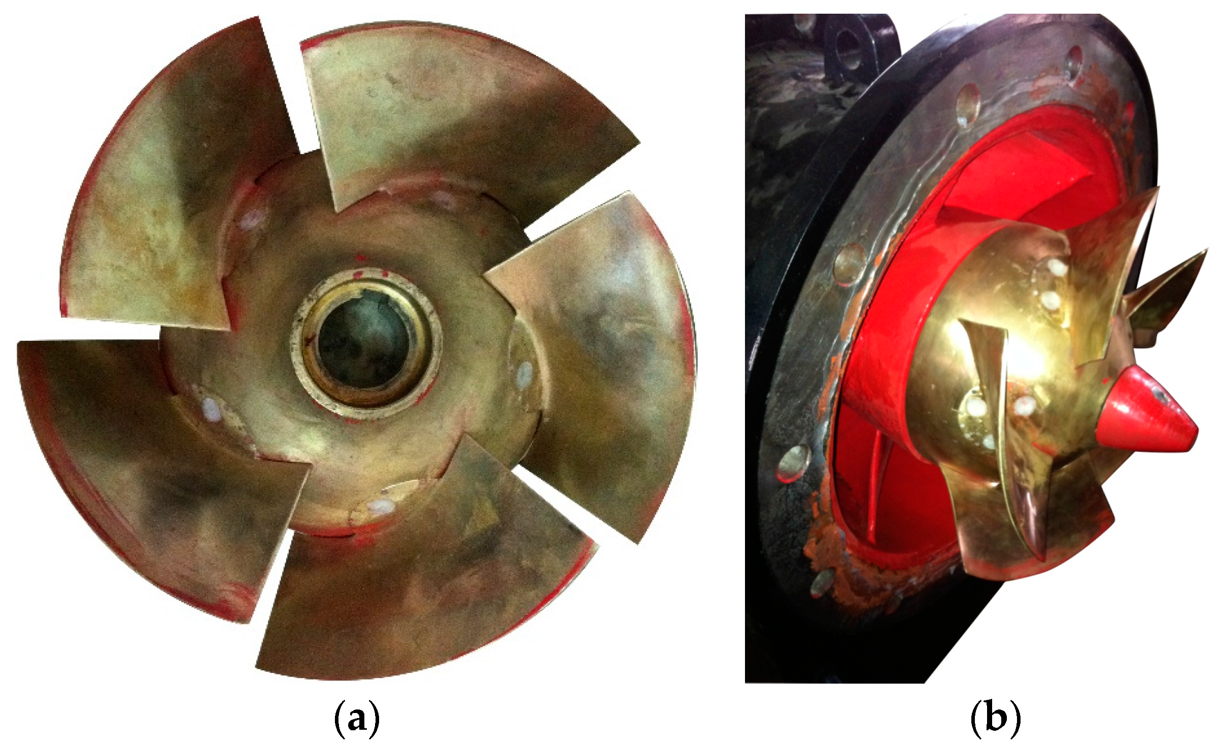
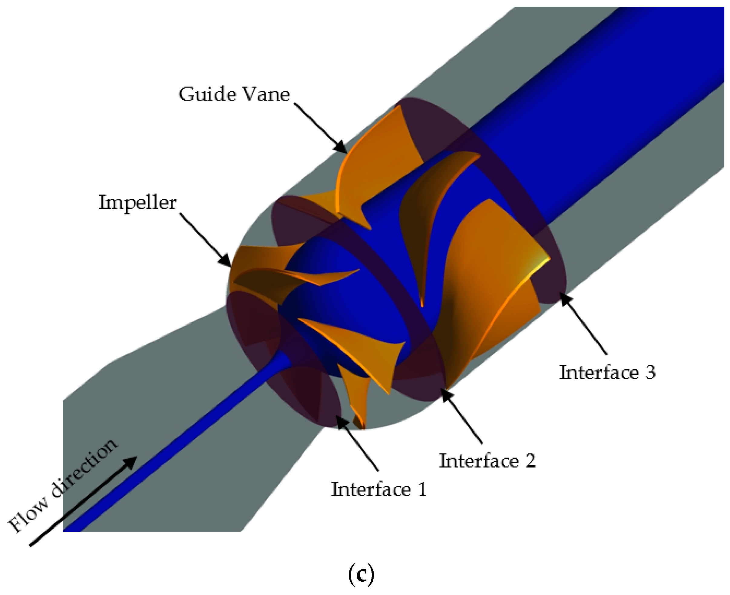
The tested mixed-flow pump was designed by the direction and inverse iteration design method [17,18,19,20]. This design method is based on the fluid continuity and motion equations and solves for the meridional velocity taking the effects of the blade shape on the flow into account. The blade shape is drawn by point-by-point integration with blade thickening and smoothing using conformal mapping. The impeller and computation domain of the mixed-flow pump are shown in Figure 1, and the main design parameters of the mixed-flow pump are listed in Table 1.
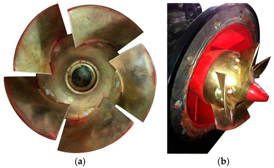
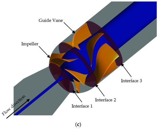
Figure 1.
Impeller and computation domain of the mixed-flow pump. (a) Impeller from upstream; (b) Impeller from downstream; (c) Computation domain.

Table 1.
Parameters for the mixed-flow pump.
2.2. Computational Mesh of Mixed-Flow Pump
The software ICEM (ANSYS Inc., Pittsburgh, PA, USA) is employed in the present paper to generate the structured mesh with hexahedron blocks for the whole computational domain. In mesh generation, the impeller and guide vane are both divided into a single channel and then the single channel is periodically rotated around the z-axis to combine as a whole.
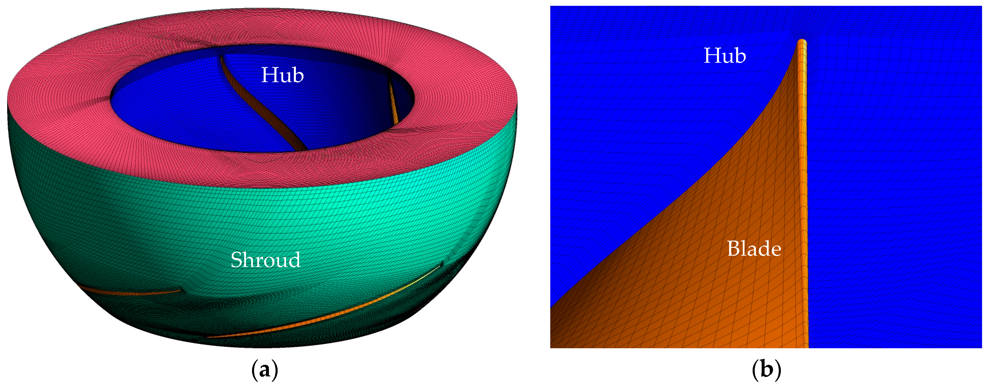
Figure 2 shows the mesh of the impeller, the O topology and partial blade encryptions, which are adopted for the purpose of higher precision in our simulation. In addition, there are nine nodes arranged near the blade root to accurately capture the flow details. Mesh quality is evaluated by the determinant (≥0.41 in impeller and ≥0.56 in guide vane) and aspect ratio (≤24.3 in impeller and ≤15.5 in guide vane), and the results show that the generated structured mesh is suitable to conduct the calculation in the present work.
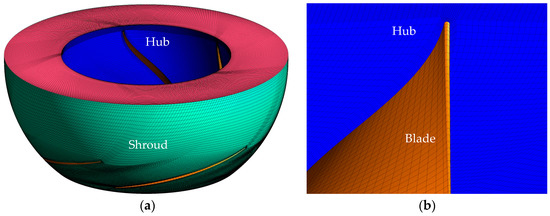
Figure 2.
Mesh of the impeller domain and topology. (a) Impeller domain; (b) O topology and encryption of blade.
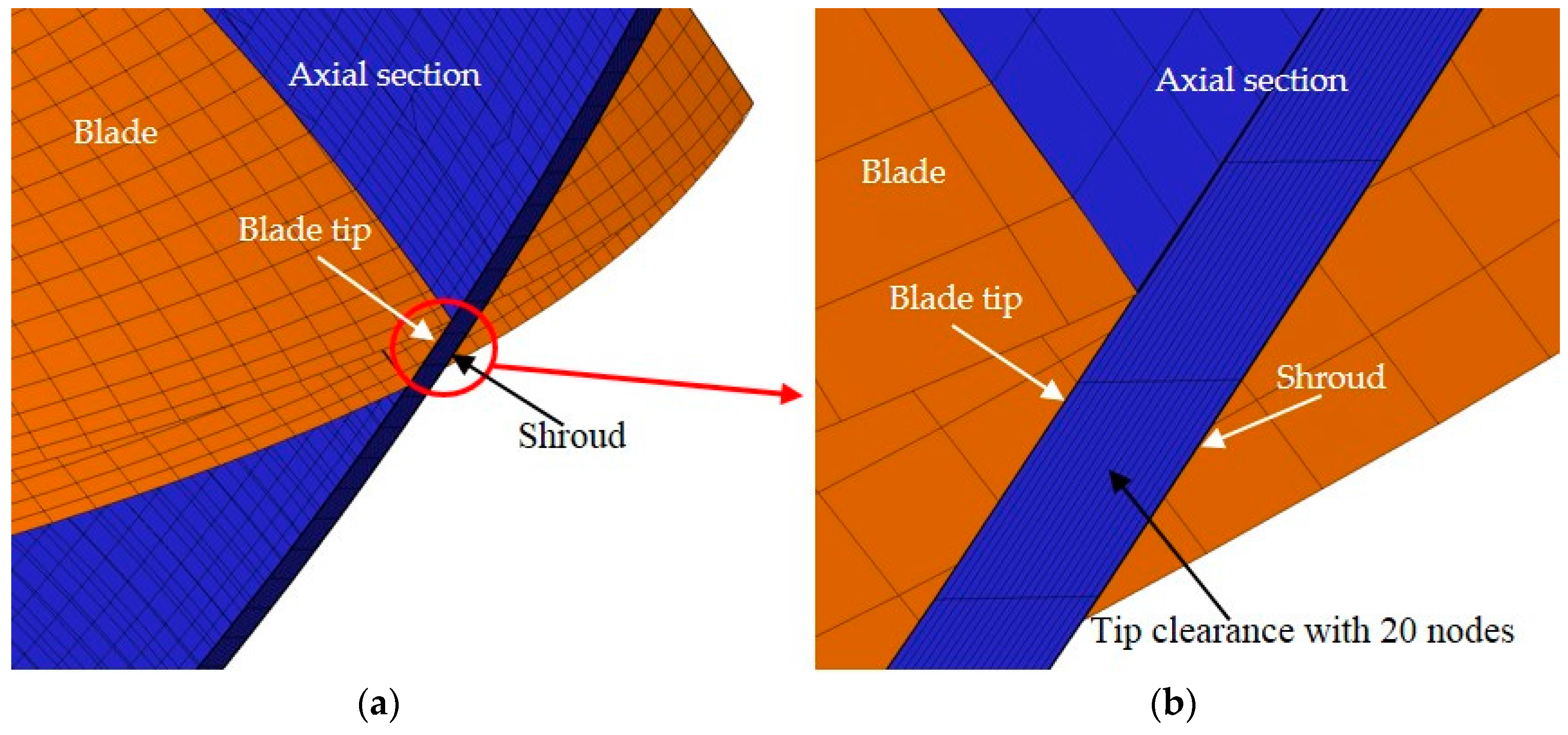
Figure 3 shows the local mesh encryption in tip clearance region, where δ is the tip clearance size. Figure 3a shows the axial section cutting the middle edge of a blade, and Figure 3b shows the local mesh details in tip clearance region. There are 20 nodes arranged in the tip clearance region to accurately capture the complex flow characteristics in this region.
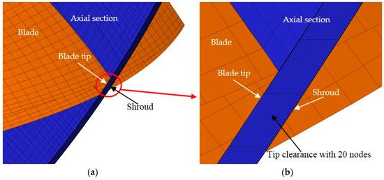
Figure 3.
Local mesh encryption in tip clearance region. (a) Axial section; (b) Mesh in tip clearance region.
3. Numerical Method and Setting
3.1. Numerical Method
The computation fluid dynamics software CFX 14.5 (ANSYS Inc., Pittsburgh, PA, USA) and the RNG k-ε turbulence model are employed in the present work. The boundary conditions are set as the total pressure at pump inlet, the mass flow rate at pump outlet and no slip wall at walls. The methods of frozen rotor and transient rotor stator are applied to coupling the rotational and stationary domains for steady and unsteady calculations, respectively [21,22,23,24].
Taking the results of the steady simulation as the initial flow field, the unsteady simulation is conducted to monitor the pressure fluctuation in the mixed-flow pump. The convergence criterion is defined as the root-mean-square residual being below 1 × 10⁻⁵.
3.2. Independence Test of Mesh Number and Time Step
To work out the minimum mesh size and the reasonable number of mesh elements is important in numerical simulation [25], so tests of the effect of the local mesh refinement in the tip clearance zone and mesh independence with total mesh number are conducted. Four sets of meshes with mesh elements from 1,862,056 to 6,235,158 are employed to validate the mesh number independence. Table 2 shows that the variation of pump head and efficiency is slight with ΔH/H1 ≤ 0.01 and Δη/η1 ≤ 0.004. Therefore, comprehensively considering calculation cost and accuracy, Mesh 2 with 3,380,806 elements is used in the present work.

Table 2.
Pump head H and efficiency η versus mesh elements.
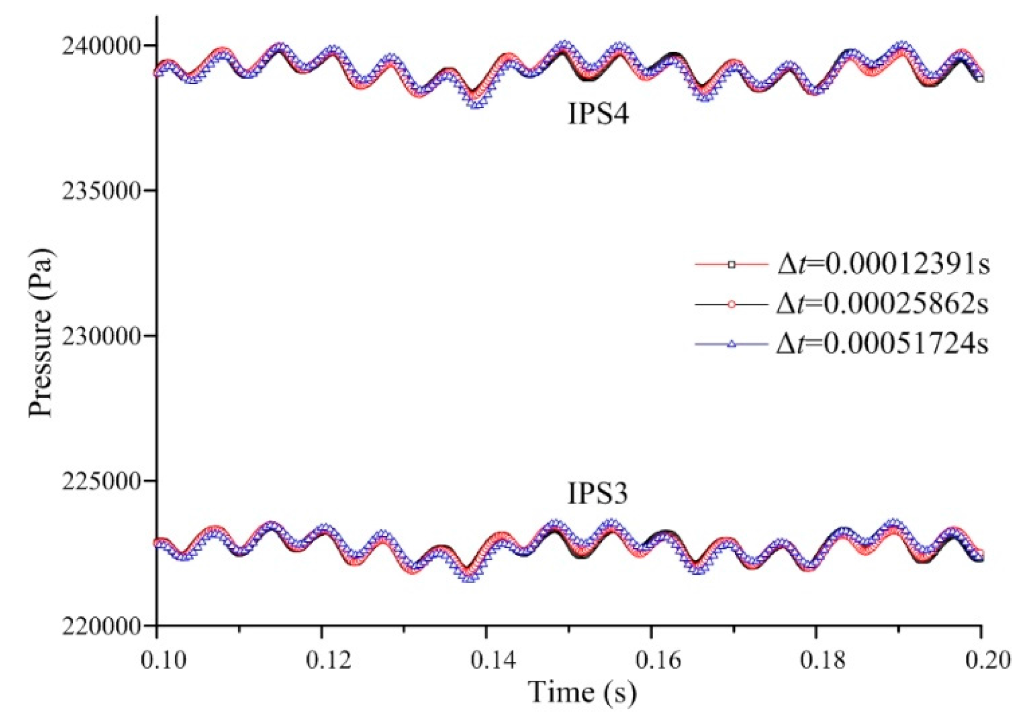
The revolution period of the impeller is T = 60/1450 s = 0.04137931 s. Three different time steps are set as 1.2931 × 10⁻⁴ s, 2.5862 × 10⁻⁴ s and 5.1724 × 10⁻⁴ s, which are 1/320 T, 1/160 T and 1/80 T, respectively, to validate the time step independence. Figure 4 shows the time histories of pressure on two monitoring points IPS3 and IPS4, which are located at the middle chord of the blade pressure side. It can be seen that the pressure fluctuation curves match perfectly at both positions, which indicates that the influence of time step Δt on calculation result can be neglected. Considering the calculation cost and accuracy, a time step of 2.5862 × 10⁻⁴ s is used in the present work.

Figure 4.
Time histories of pressure fluctuation on IPS3 and IPS4.
3.3. Simulation Accuracy Validation
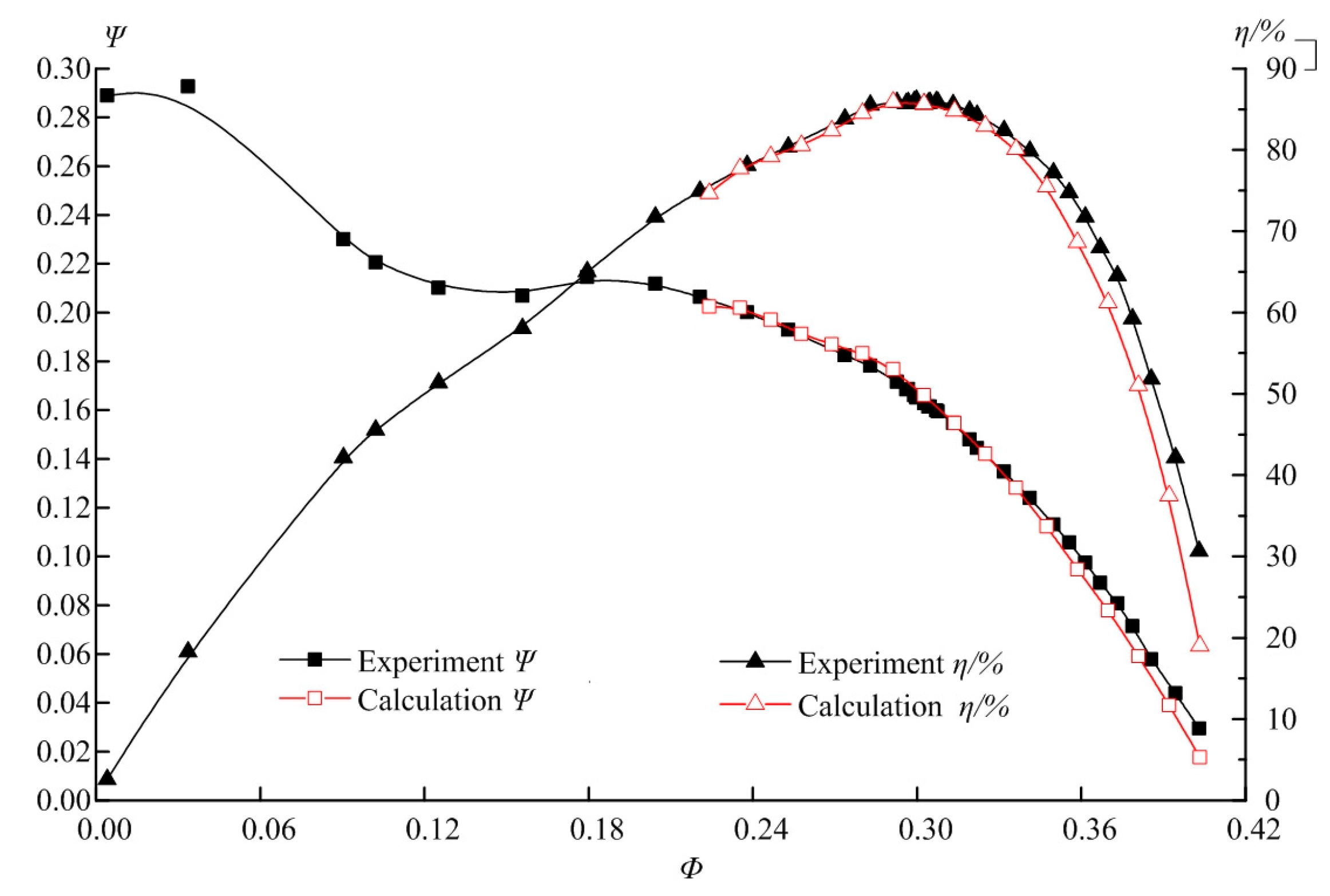
The experiment of tested pump is carried out on the test apparatus at Beifang Investigation, Design & Research Co., Ltd., Tianjin, China and the test bench mainly consists of a water supply section, a pump section and an exhaust section. The pump flow rate is measured by an electromagnetic flowmeter (LDG-500S, Shanghai Guanghua Instrument Co., Ltd, Shanghai, China), with a measurement error in the range of ±0.2%. The pump head is tested by two pressure transmitters (V15712-HD1A1D7D, Newsruipu Instrument Co., Ltd, Zhengzhou, China) with measurement errors in the range of ±0.1%. The pump torque and the rotational speed are measured by a torque speed sensor (JCZL2-500, Powerlink, Instrument Co., Ltd, Changsha, China) with a measurement error in the range of ±0.1%. On the basis of random error of this test rig, which is in the range of ±0.1%, the comprehensive error of pump performance measurement is estimated to be within ±0.28% through uncertainty analysis of the system. Considering the main flow rate range and the test range of the pump, the simulation is carried out at 17 working points. Figure 5 shows the comparison of performance curves of head and efficiency between the experiment and simulation results. The simulation performance curve is in remarkable agreement with the experiment result, especially in the vicinity of design condition, which validates the accuracy and reliability of the numerical method. The flow rate and head are normalized by specific flow rate and specific head , where u2 is the circumferential velocity at the impeller outlet.
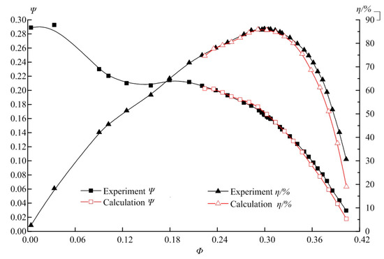
Figure 5.
Comparison of pump performance between experiment and calculation results.
4. Result and Discussion
4.1. Energy Performance of Mixed-Flow Pump with Different Tip Clearance Sizes
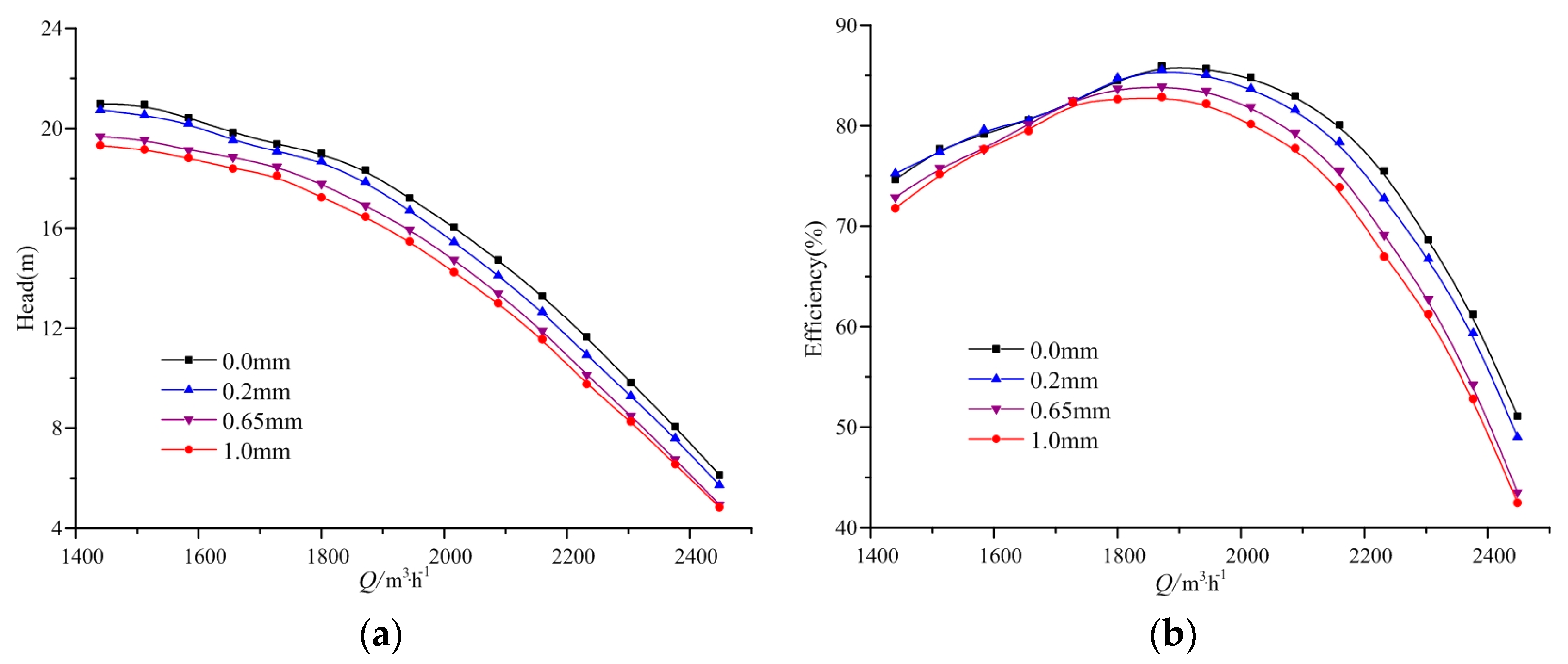
Figure 6 shows the variation of pump head and efficiency with different tip clearance sizes. The results show that the pump head decreases gradually with increasing flow rate, and when the flow rate is beyond 1800 m3/h, the relationship between flow rate and head is nearly linear. For different tip clearances, the pump head decreases with the increasing tip clearance at all flow rates, and the variation trend of the efficiency is similar as that of the head, except for the points below 1728 m3/h, where the flow pattern is more complicated than that of the design and large flow rates. This indicates that the tip clearance has a significant impact on the energy performance of mixed-flow pumps, and the influence level is different under different flow rates.
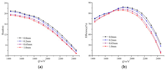
Figure 6.
Variation of pump head and efficiency for different tip clearance sizes. (a) Variation of head; (b) variation of efficiency.
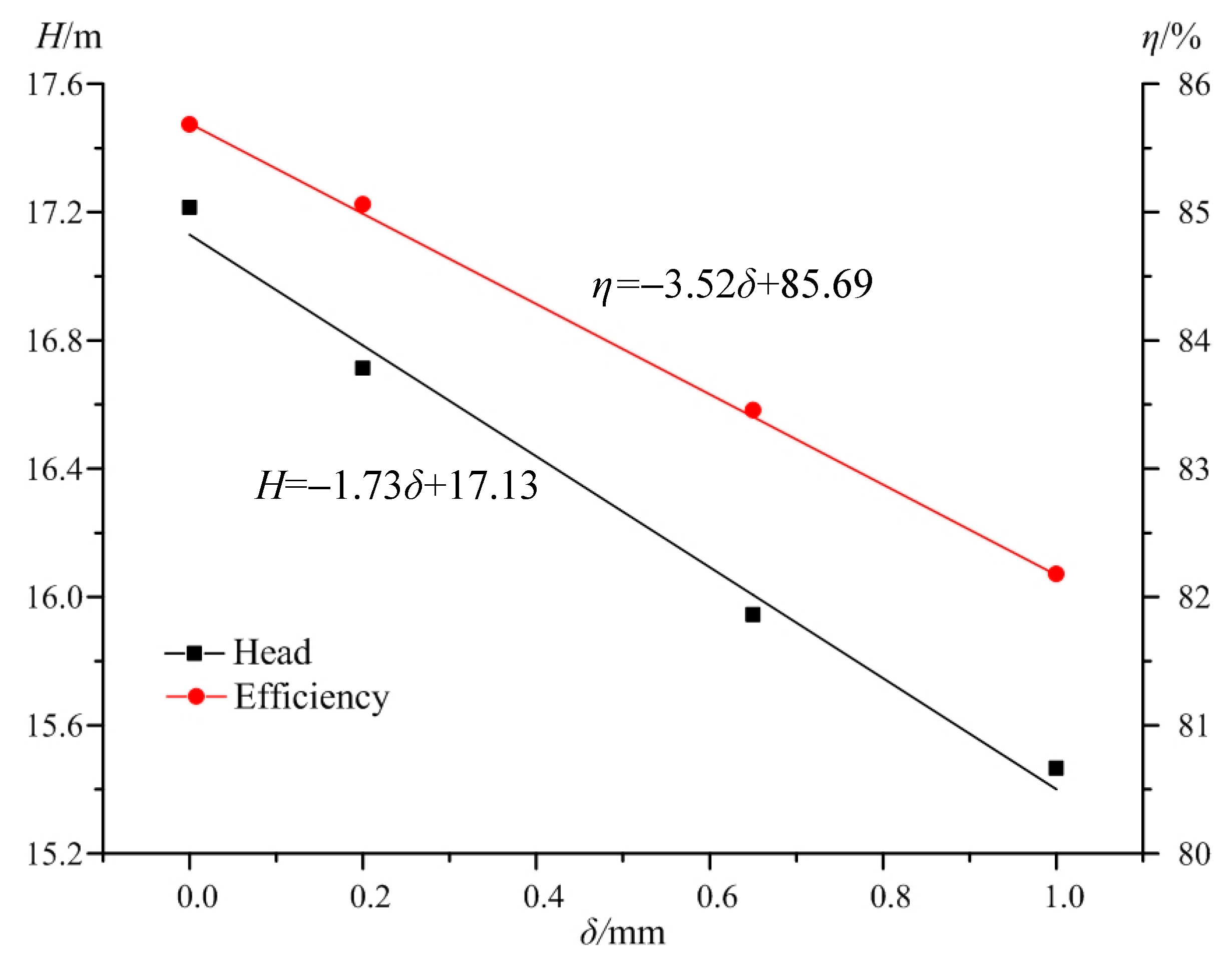
Figure 7 shows the variations of pump head and efficiency with different tip clearance sizes at the design flow rate. With the increasing tip clearance size, the pump head and efficiency decrease accordingly with a nearly linear rule. Therefore, the relationship between pump head and tip clearance size and that between pump efficiency and tip clearance size can be expressed by two first-order fitting formulas: H = −1.73δ + 17.13 and η = −3.52δ + 85.69, respectively.
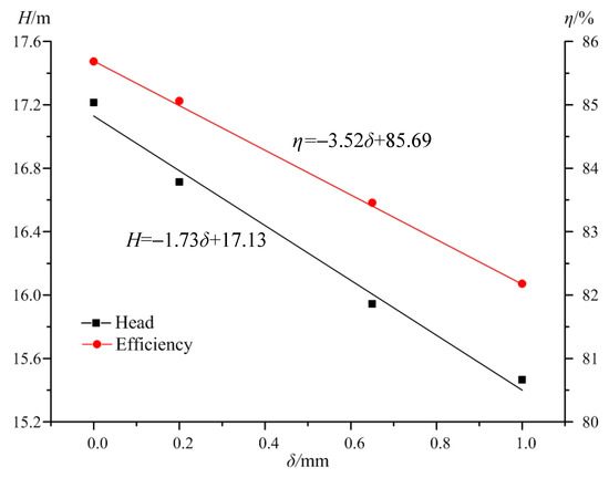
Figure 7.
Pump head and efficiency with different tip clearance sizes at design flow rate.
4.2. Flow Pattern in Tip Clearance Region
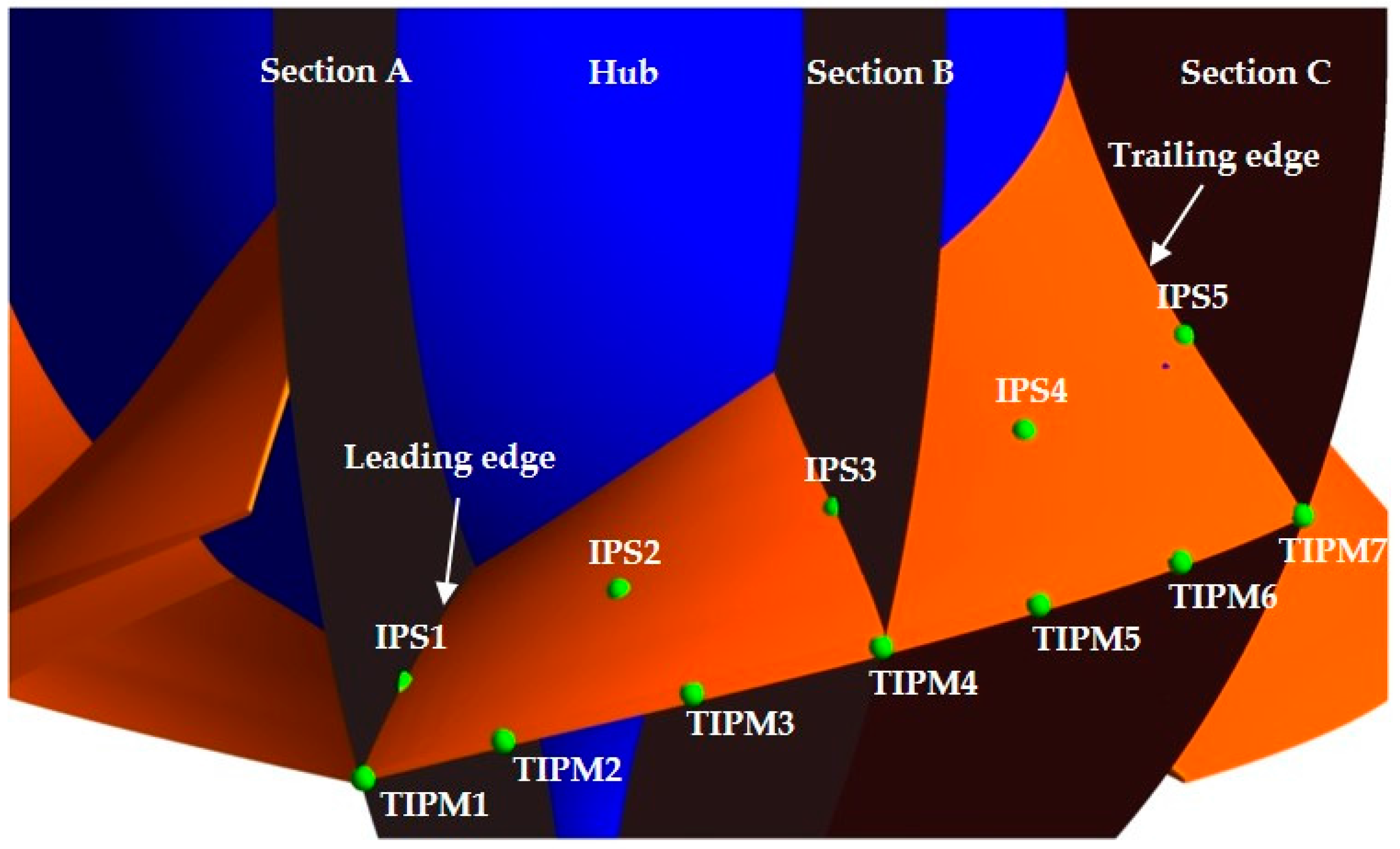
Figure 8 shows the axial sections and monitoring points in the impeller. Sections A, B and C are the axial sections cutting the blade leading edge, middle edge and trailing edge, respectively. Five points are named as IPS1–5 on the blade pressure side and another five points are named as ISS1–5 on the blade suction side corresponding to the same positions of IPS1–5. Seven points on the blade tip are labelled as TIPM1–7. The number of monitoring points is sequentially ordered from blade leading edge to trailing edge as shown in Figure 8.
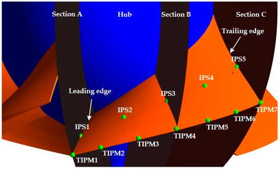
Figure 8.
Axial sections and monitoring points in impeller.
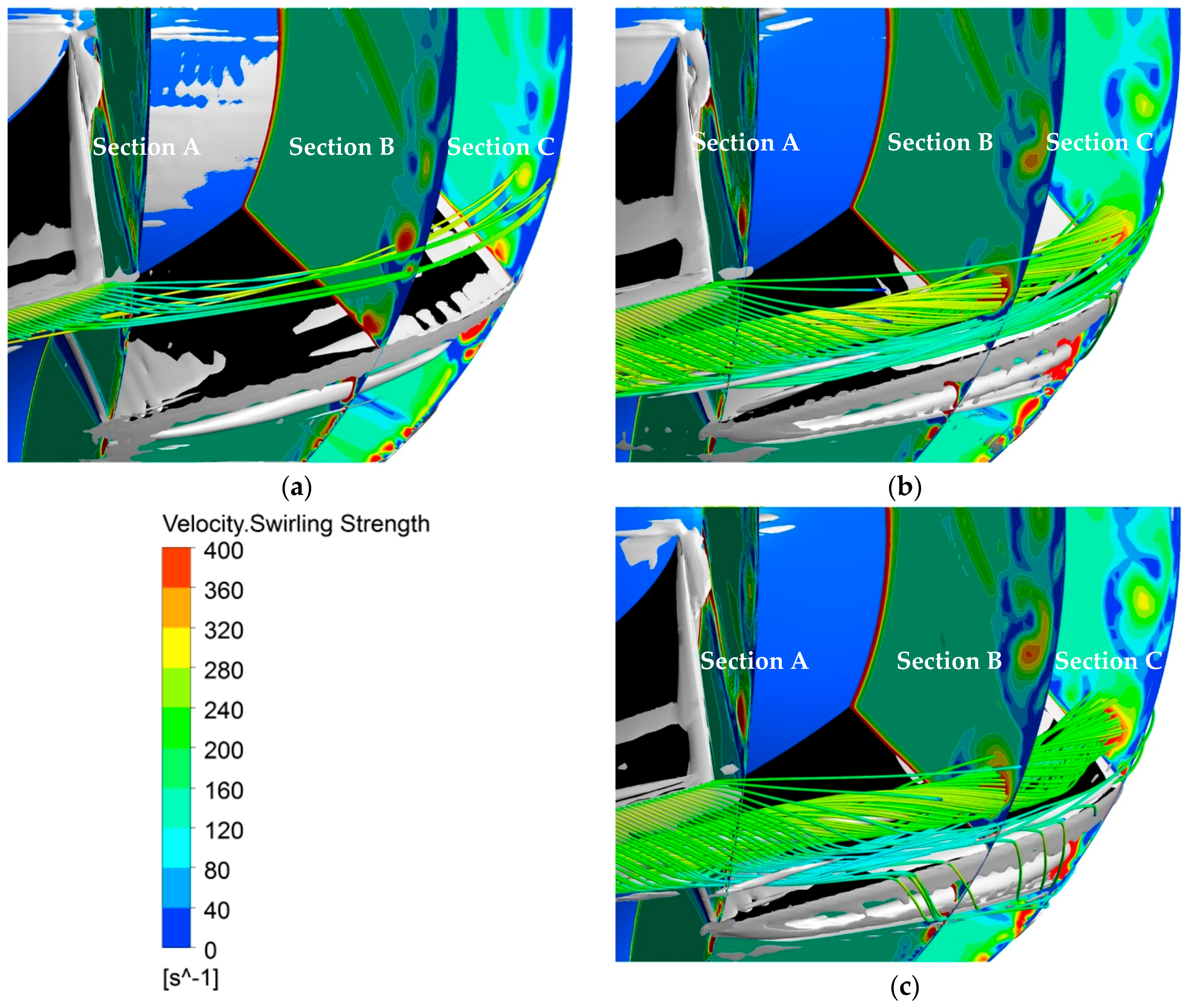
Figure 9 shows the three dimensional streamlines and velocity swirling strength distribution on Sections A, B and C. To analyze the formation and development of the three dimensional tip leakage vortex in the blade to blade channel and tip clearance region, the streamlines are released from the blade tip. The vorticity is defined by the Q criterion.
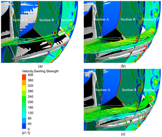
Figure 9.
Streamline, velocity swirling strength and vorticity (Q = 5 × 10⁵ s−2) in impeller. (a) δ = 0.2 mm; (b) δ = 0.65 mm; (c) δ = 1.0 mm.
Under the condition of δ = 0.2 mm, the main and secondary leakage vortexes are very thin, thus the impact on the main flow is weak. When δ = 0.65 mm, the main leakage vortex is significantly enhanced and the secondary leakage vortex also grows. The entrainment effect of the leakage vortex greatly strengthens, and then most streamlines wrap around the leakage vortex. Meanwhile, the position of the maximum value of velocity swirling strength moves towards the flow channel center thus strengthening the pressure fluctuations in a larger region. Under the conditon δ = 1.0 mm, the main leakage vortex is further enhanced, and the second leakage vortex gradually converges with the main vortex. Nearly all the streamlines wrap around the leakage vortex and extend to the next flow passage along the tip clearance.
As the tip clearance size increases, the separation between the main leakage vortex and the secondary leakage vortex becomes intense, and more leakage flow crosses through the tip clearance. The curl strength of the streamlines is also intensified and makes the flow pattern in channel more disordered, thus strengthening the pressure fluctuations in the pump.
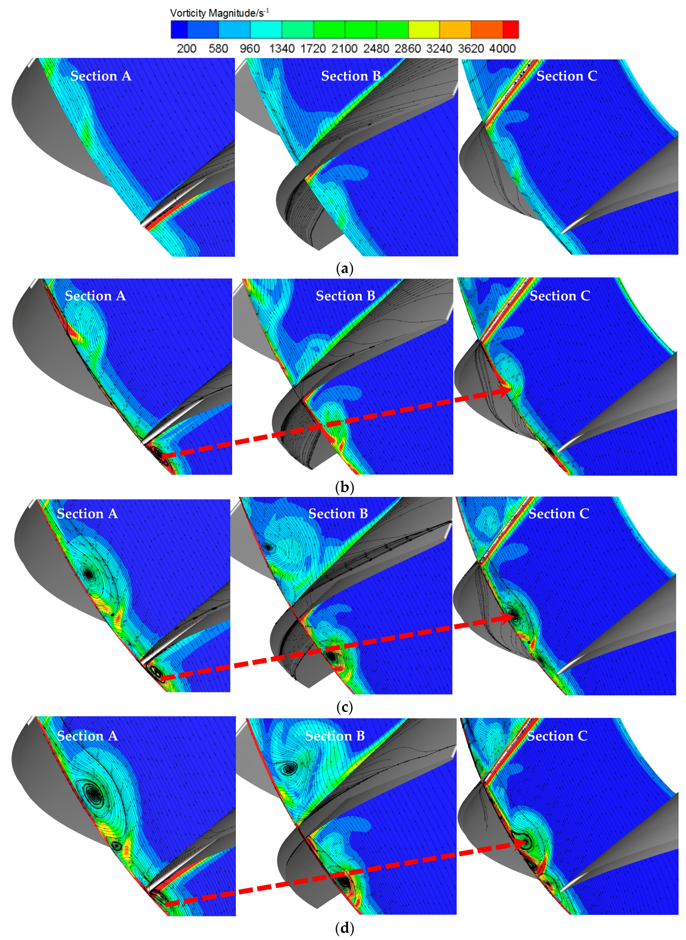
Figure 10 shows the streamline distribution on Section A, Section B and Section C for a blade. In Figure 10a, the streamlines on the axial sections are fluent and homogeneous at the three locations of leading edge, middle edge and trailing edge. When the tip clearance increases to δ = 0.2 mm, 0.65 mm and 1.0 mm, the leakage flow and leakage vortex appear in tip clearance region as shown in Figure 10b–d. As the tip clearance size increases, the leakage vortex rapidly develops along the flow direction.
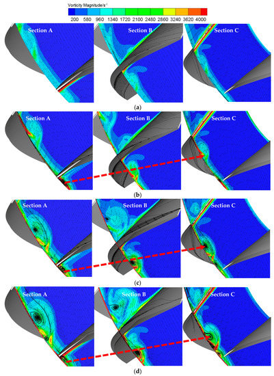
Figure 10.
Streamline and vortex distribution on axial sections. (a) δ = 0.0 mm; (b) δ = 0.2 mm; (c) δ = 0.65 mm; (d) δ = 1.0 mm.
On Section A, as shown in Figure 10b–d, the vortex upstream of the tip remains nearly the same when the tip clearance size increases, while the vortex downstream of the tip drastically develops. The vortex core is formed at δ = 0.2 mm, and becomes strong at δ = 0.65 mm. Then it splits into two cores at δ = 0.65 mm and 1.0 mm. On Section B, as shown in Figure 10b–d, the vortex is not obvious at δ = 0.2 mm, but the leakage flow crossing the tip clearance can be observed. At δ = 0.65 mm and 1.0 mm, the vortex downstream of the tip rapidly expands to the flow channel and greatly influences the main flow. On Section C, as shown in Figure 10b–d, the vortex appears downstream of the tip, and the number of vortex cores increases from one to three as δ increases from 0.2 mm to 1.0 mm.
As the tip clearance size increases, the leakage vortex rapidly develops to the flow channel center, and has a considerable effect on the main flow in a region about 50% of the blade to the blade channel at δ = 1.0 mm. The significant leakage vortex at δ = 1.0 mm will result in the extremely disordered flow pattern and violent pressure fluctuations in the impeller.
For δ = 0.2 mm, 0.65 mm and 1.0 mm, the trajectories of the vortex core from Section A to Section C are nearly the same, as shown in Figure 10b–d. This phenomenon might be affected by the blade geometry and operating flow rate.
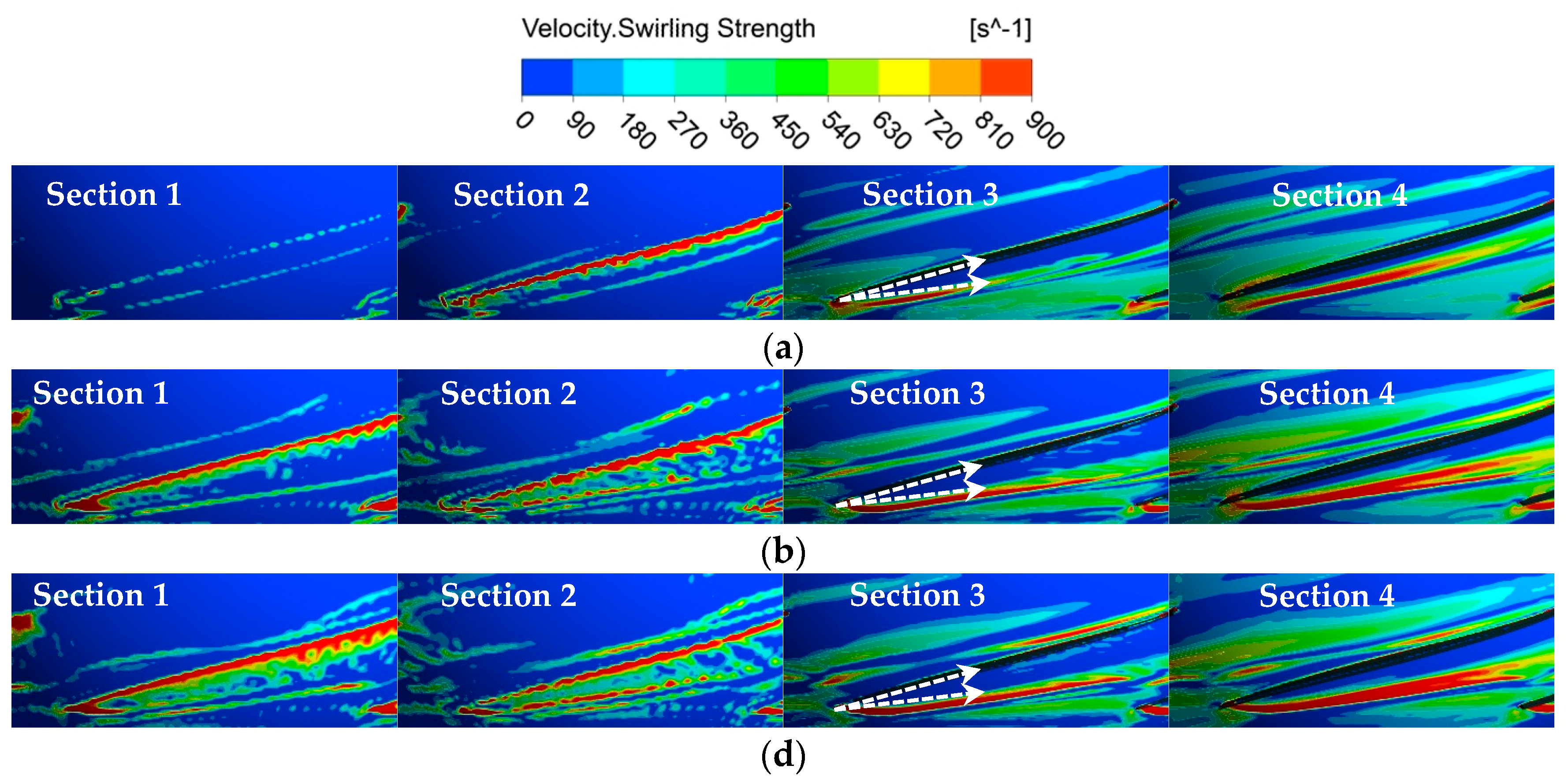
Figure 11 shows the velocity swirling strength on different circumferential sections, including Section 1 at the middle span of tip clearance height, Section 2 at blade tip, Section 3 at r/R = 99% and Section 4 at r/R = 98%, where R is the radius of corresponding shroud and r is the radius of the selected section. The radii of Sections 3 and 4 are less than that of blade tip, so the two sections will cut the blade.
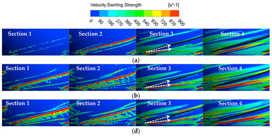
Figure 11.
Velocity swirling strength distribution on different circumferential sections. (a) δ = 0.2 mm; (b) δ = 0.65 mm; (c) δ = 1.0 mm.
As the tip clearance size increases, it is obvious that the velocity swirling strength becomes stronger at the same circumferential section. On Sections 1 and 2 in the tip clearance, two separate vortexes are obvious in the vicinity of the blade tip, and even a third leakage vortex can be clearly observed when the clearance increases to δ = 1.0 mm. The vortex region disperses as δ increases, which causes the leakage vortex to develop into the channel interior and affect a larger region when the tip clearance increases. On Sections 3 and 4, the black part represents the blade. It is shown that the leakage vortex is mainly below the blade and the main leakage vortex region becomes wider and longer as δ increases.
The leakage separation angle is defined as the angle between the main leakage vortex and blade on the circumferential section. It is shown that the leakage separation angle remains at the same value of 10° as the tip clearance increases on Section 3, which means that the direction of the leakage flow in the vicinity of blade tip is mainly affected by the blade stacking law. However, on Section 4 of r/R = 98%, a bit farther away from the blade tip than Section 3, the leakage separation angle significantly increases from δ = 0.2 mm to δ = 1.0 mm. It is seen that the leakage flow close to the impeller center quickly propagates and blends with the increasing tip clearance, so the pump with a larger tip clearance has clearly deteriorated performance due to the serious mixing process of the main flow and the leakage flow.
Another phenomenon is that there is a bifurcation in the main leakage flow on Section 4 when the tip clearance increases to δ = 0.65 mm and δ = 1.0 mm, and this phenomenon corresponds to the streamline separation as shown in Figure 9. The separated leakage flow goes through the tip to the blade suction side. The pressure of the leakage flow is low due to the vortex, and when this leakage flow arrives at the blade suction side, the pressure in this region will reduce even more. This large pressure difference between the blade pressure side and suction side in a blade to blade channel may induce a secondary flow from the high pressure side to the low pressure side, and this undesired phenomenon will greatly deteriorate the flow field and decrease the pump performance.
4.3. Pressure Fluctuation in Mixed-Flow Pump
Table 3 shows the flow conditions for the transient simulation under different tip clearance sizes. Taking the results of the steady simulation as the initial flow field, the transient calculation is conducted for more than 15 impeller revolutions, and the data of the last 10 cycles is used to perform the Fast Fourier Transform (FFT). Then the frequency characteristics of the pressure fluctuations on the monitoring points are obtained.

Table 3.
Flow conditions for transient simulation.
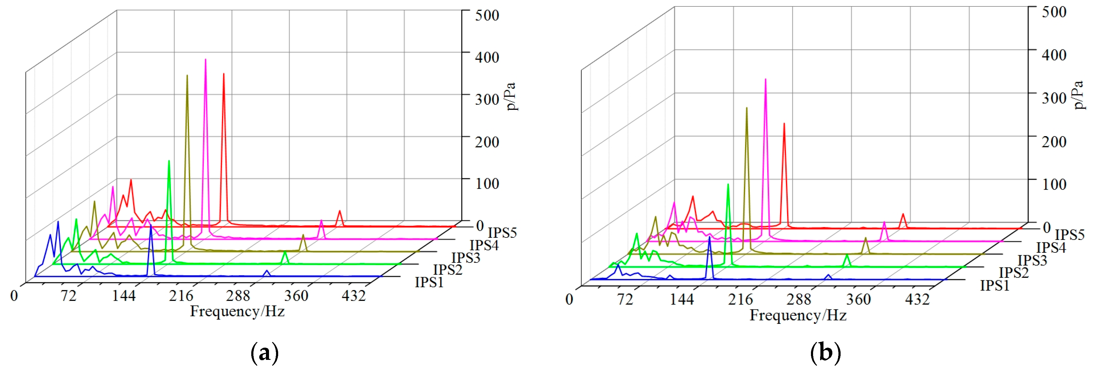
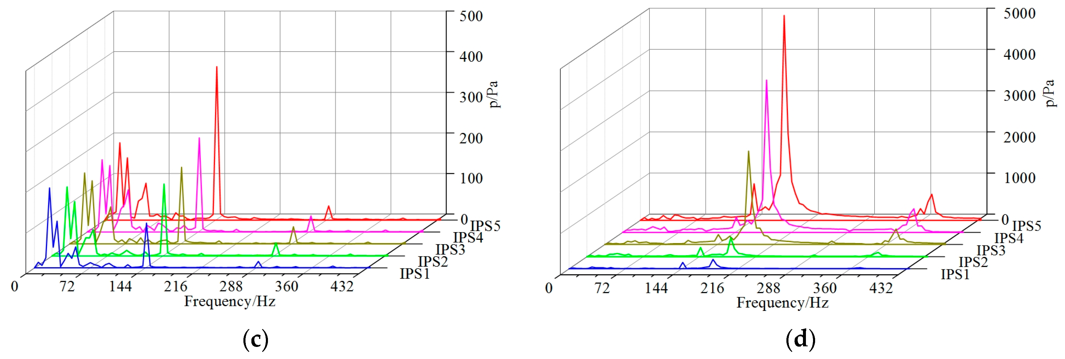
Figure 12 shows the pressure fluctuation spectra on monitoring points IPS1–IPS5 on the blade pressure side. For tip clearances of 0.0 mm, 0.2 mm and 0.65 mm, the dominant frequencies are mainly 145 Hz, corresponding to six times the impeller rotation frequency, which is closely related to the rotor stator interaction between the impeller and guide vane. For different tip clearance sizes, as the pressure increases due to the power input from the main shaft, the maximum amplitudes of the dominant frequencies synchronously increase from IPS1 to IPS4, but the maximum amplitudes drop at IPS5 for δ = 0.0 mm and δ = 0.2 mm, which can be ascribed to the jet wake flow structure at the impeller outlet. For a tip clearance of 1.0 mm, the amplitudes of the dominant frequencies are significantly enhanced, especially at the blade trailing edge. The reason is that the pressure fluctuation is not only influenced by the impeller rotation, but also by the leakage flow. When the tip clearance size increases to 1.0 mm, the leakage flow is greatly strengthened and the flow pattern becomes more complicated.
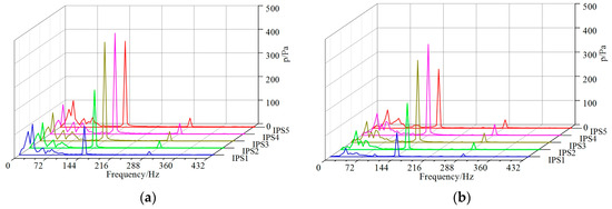
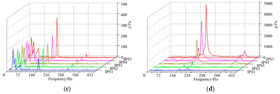
Figure 12.
Spectrum analysis of pressure fluctuations on IPS1–IPS5. (a) δ = 0.0 mm; (b) δ = 0.2 mm; (c) δ = 0.65 mm; (d) δ = 1.0 mm.
Table 4 shows the dominant frequencies and maximum amplitudes of the pressure fluctuations on IPS1–5 and ISS1–5. In comparison to the blade pressure side, the maximum amplitudes of the monitoring points on the suction side are lower, except for the case of ISS1. The reason is that the leakage vortex is strong at this position and this induces a larger pressure fluctuation than that at IPS1; the detailed flow pattern has been discussed in Section 4.2. For δ = 1.0 mm, the dominant frequencies on IPS1–5 and ISS1–5 increase to 184 Hz, which is related to the enhanced leakage flow. The last column of Table 4 clearly shows that all pressure fluctuations at δ = 1.0 mm have larger energy than that of other tip clearance sizes, and the degree of increase is severe.

Table 4.
Spectrum analysis of pressure fluctuations on IPS1–5 and ISS1–5.
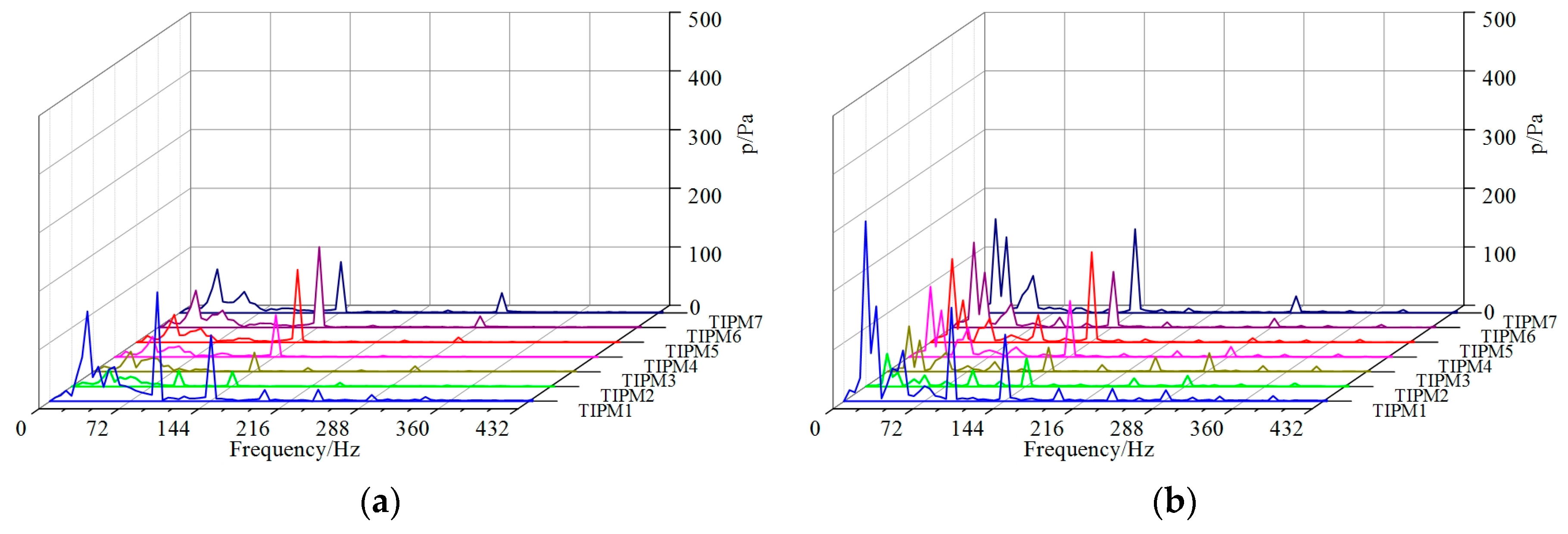
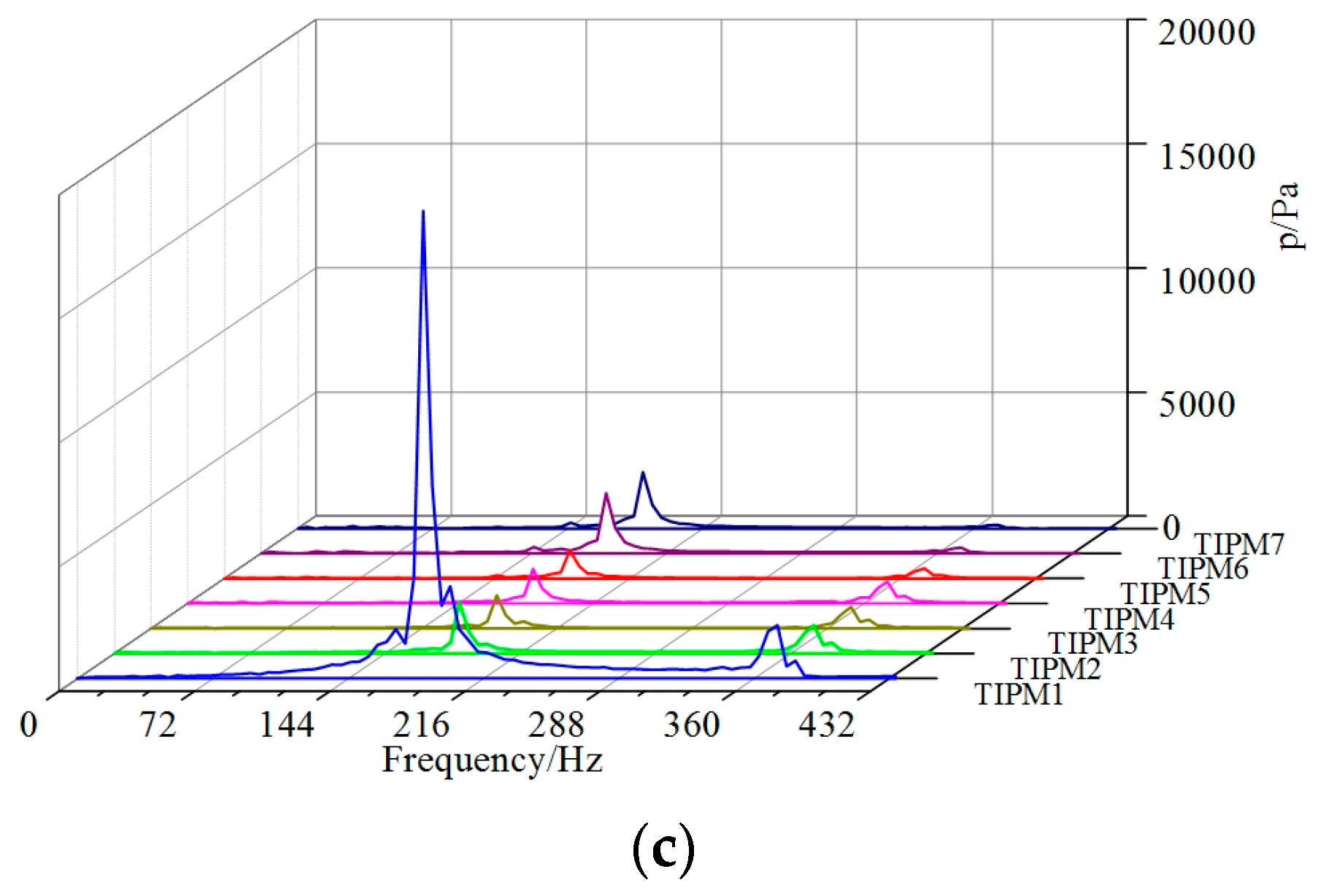
Figure 13 shows the pressure fluctuation spectra at monitoring points TIPM1-TIPM7 on the blade tip. For δ = 0.2 mm and δ = 0.65 mm, the high amplitudes are mainly concentrated at low frequencies, while for δ = 1.0 mm, the dominant frequencies move to 184 Hz, and the variation trend is the same as that of blade due to the complicated flow pattern. Meanwhile, the maximum amplitudes of the dominant frequencies greatly increase when the tip clearance size reaches 1.0 mm.
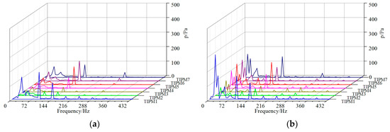
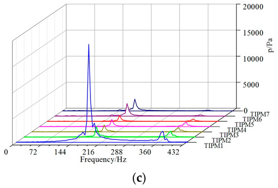
Figure 13.
Spectrum analysis of the pressure fluctuations on TIPM1–TIPM7. (a) δ = 0.2 mm; (b) δ = 0.65 mm; (c) δ = 1.0 mm.
Table 5 shows the dominant frequencies and maximum amplitudes of the pressure fluctuations on TIPM1-TIPM7. The last column of Table 5 clearly shows that all pressure fluctuations at δ = 1.0 mm have larger energy than that of other tip clearance sizes. The maximum magnification occurs on TIPM1, which is induced by the severe leakage vortex at the blade leading edge at δ = 1.0 mm.

Table 5.
Spectrum analysis of pressure fluctuations on TIPM1–TIPM7.
5. Conclusions
A systematic investigation into the influence of tip clearance size on energy performance and pressure fluctuation for a mixed-flow pump is conducted in the present research. Based on the numerical simulation and analysis results, the following main conclusions can be drawn:
- (1)
- With the increase of tip clearance size, the pump head and efficiency decrease. The relationship between pump head and tip clearance size and that between pump efficiency and tip clearance size are expressed by two first-order fitting formulas.
- (2)
- Obvious leakage flow induces a leakage vortex, which greatly intensifies when the tip clearance size increases, and further affects the main flow in blade to blade channel. The leakage separation angle near the blade tip remains at the same value of 10° for different tip clearance sizes.
- (3)
- The maximum amplitudes of the pressure fluctuations dramatically increase in the impeller, especially on the blade tip when the tip clearance size increases from 0.0 mm to 1.0 mm, and the dominant frequencies also grow from 145 Hz to 184 Hz due to the considerable leakage flow.
Acknowledgments
This work has been supported by the Tsinghua University Initiative Scientific Research Program (Grant number 2014z21041), the Beijing Natural Science Foundation (Grant number 3164045), and the National Natural Science Foundation of China (Grant numbers 51579006, 51679122).
Author Contributions
Yabin Liu and Lei Tan conceived and designed the experiments and simulations; Yabin Liu, Yue Hao and Yun Xu performed the experiments and simulations; Yabin Liu and Lei Tan analyzed the data and wrote the paper.
Conflicts of Interest
The authors declare no conflict of interest.
References
- Kang, S.; Hirsch, C. Experimental study on the three-dimensional flow within a compressor cascade with tip clearance: Part I—Velocity and pressure fields. J. Turbomach. 1993, 115, 435–443. [Google Scholar] [CrossRef]
- Kang, S.; Hirsch, C. Experimental study on the three dimensional flow within a compressor cascade with tip clearance: Part II—The tip leakage vortex. J. Turbomach. 1993, 115, 444–450. [Google Scholar] [CrossRef]
- Matsunuma, T. Effects of Reynolds number and freestream turbulence on turbine tip clearance flow. J. Turbomach. 2006, 128, 166–177. [Google Scholar] [CrossRef]
- Jang, C.M. Analysis of Vortical Flow Field in a Propeller Fan by LDV Measurements and LES—Part I: Three-dimensional vortical flow structures. J. Fluids Eng. 2001, 123, 748–754. [Google Scholar] [CrossRef]
- Wernet, M.P.; Van Zante, D.; Strazisar, T.J.; John, W.T.; Prahst, P.S. Characterization of the tip clearance flow in an axial compressor using 3-D digital PIV. Exp. Fluids 2005, 39, 743–753. [Google Scholar] [CrossRef]
- Wu, H.; Miorini R, L.; Tan, D.; Katz, J. Turbulence within the tip-leakage vortex of an axial waterjet pump. AIAA J. 2012, 50, 2574–2587. [Google Scholar] [CrossRef]
- Wu, H.; Tan, D.; Miorini, R.L.; Katz, J. Three-dimensional flow structures and associated turbulence in the tip region of a waterjet pump rotor blade. Exp. Fluids 2011, 51, 1721–1737. [Google Scholar] [CrossRef]
- Wu, H.; Miorini, R.L.; Katz, J. Measurements of the tip leakage vortex structures and turbulence in the meridional plane of an axial water-jet pump. Exp. Fluids 2011, 50, 989–1003. [Google Scholar] [CrossRef]
- Miorini, R.L.; Wu, H.; Katz, J. The internal structure of the tip leakage vortex within the rotor of an axial waterjet pump. J. Turbomach. 2012, 134, 031018. [Google Scholar] [CrossRef]
- Zhang, D.S.; Shi, W.; van Esch, B.P.M.B.; Shi, L.; Dubuisson, M. Numerical and experimental investigation of tip leakage vortex trajectory and dynamics in an axial flow pump. Comput. Fluids 2015, 112, 61–71. [Google Scholar] [CrossRef]
- Zhang, D.S.; Shi, W.; Pan, D.; Dubuisson, M. Numerical and experimental investigation of tip leakage vortex cavitation patterns and mechanisms in an axial flow pump. J. Fluids Eng. 2015, 137, 121103. [Google Scholar] [CrossRef]
- Zhang, D.S.; Shi, L.; Shi, W.; Zhao, R.; Wang, H.; van Esch, B.P.M.B. Numerical analysis of unsteady tip leakage vortex cavitation cloud and unstable suction-side-perpendicular cavitating vortices in an axial flow pump. Int. J. Multiph. Flow 2015, 77, 244–259. [Google Scholar] [CrossRef]
- Yang, S.S.; Liu, H.L.; Kong, F.Y.; Xia, B.; Tan, L. Effects of the radial gap between impeller tips and volute tongue influencing the performance and pressure pulsations of pump as turbine. J. Fluids Eng. 2014, 136, 054501. [Google Scholar] [CrossRef]
- Feng, J.; Luo, X.; Guo, P.; Wu, G. Influence of tip clearance on pressure fluctuations in an axial flow pump. J. Mech. Sci. Technol. 2016, 30, 1603–1610. [Google Scholar] [CrossRef]
- You, D.; Wang, M.; Moin, P.; Wang, M. Study of tip-clearance flow in turbomachines using large-eddy simulation. Comput. Sci. Eng. 2004, 6, 38–46. [Google Scholar]
- You, D.; Wang, M.; Moin, P.; Mittal, R. Vortex dynamics and low-pressure fluctuations in the tip-clearance flow. J. Fluids Eng. 2007, 129, 1002–1014. [Google Scholar] [CrossRef]
- Tan, L.; Cao, S.; Wang, Y.; Zhu, B. Direct and inverse iterative design method for centrifugal pump impellers. Proc. Inst. Mech. Eng. Part A J. Power Energy 2012, 226, 764–775. [Google Scholar] [CrossRef]
- Bing, H.; Cao, S. Three-dimensional design method for mixed flow pump blades with controllable blade wrap angle. Proc. Inst. Mech. Eng. Part A J. Power Energy 2013, 227, 567–584. [Google Scholar] [CrossRef]
- Tan, L.; Zhu, B.; Cao, S.; Bing, H.; Wang, Y. Influence of blade wrap angle on centrifugal pump performance by numerical and experimental study. Chin. J. Mech. Eng. 2014, 27, 171–177. [Google Scholar] [CrossRef]
- Bing, H.; Cao, S. Parametrization of blade leading and trailing edge positions and its influence on mixed- flow pump performance. Proc. Inst. Mech. Eng. Part C J. Mech. Eng. Sci. 2014, 228, 703–714. [Google Scholar] [CrossRef]
- Tan, L.; Zhu, B.; Cao, S.; Wang, Y.; Wang, B. Numerical simulation of unsteady cavitation flow in a centrifugal pump at off-design conditions. Proc. Inst. Mech. Eng. Part C J. Mech. Eng. Sci. 2014, 228, 1994–2006. [Google Scholar]
- Tan, L.; Zhu, B.; Wang, Y.; Cao, S.; Gui, S. Numerical study on characteristics of unsteady flow in a centrifugal pump volute at partial load condition. Eng. Comput. 2015, 32, 1549–1566. [Google Scholar] [CrossRef]
- Qu, W.; Tan, L.; Cao, S.; Wang, Y.; Xu, Y. Numerical investigation of clocking effect on a centrifugal pump with inlet guide vanes. Eng. Comput. 2016, 33, 465–481. [Google Scholar] [CrossRef]
- Hao, Y.; Tan, L.; Liu, Y.; Zhang, J.; Zhu, B. Energy Performance and Radial Force of a Mixed-Flow Pump with Symmetrical and Unsymmetrical Tip Clearances. Energies 2017, 10, 57. [Google Scholar] [CrossRef]
- Carravetta, A.; Fecarotta, O.; Ramos, H. Numerical simulation on pump as turbine: Mesh reliability and performance concerns. In Proceedings of the International Conference on Clean Electrical Power, Ischia, Italy, 14–16 June 2011; pp. 169–174.
© 2017 by the authors. Licensee MDPI, Basel, Switzerland. This article is an open access article distributed under the terms and conditions of the Creative Commons Attribution (CC BY) license ( http://creativecommons.org/licenses/by/4.0/).

