1. Introduction
With the rapid increase in the number of multimedia-capable and internet-connected devices, there is an increasing need for further development of wireless technology in order to meet these demands. The most common means of data consumption are watching high-definition (HD) videos and accessing cloud-based services. Most of the data consumption has been observed to occur in indoor environments, where users consume data using their smart devices at their residence, in shopping malls, in aircrafts, and in other vehicles. This high demand of data usage is expected to continue to grow in the foreseeable future. With highly-congested radio frequency (RF) bands, visible light communication (VLC) is considered to be a supplementary technology that can be adopted to bridge the gap between user demand and capacity.
VLC uses light emitting diodes (LEDs) to accomplish illumination and data communication. VLC has shown potential to be an integral part of the upcoming 5G network. While the market has continued to push the limits of the network data rate and capacity offered to users, the wireless communication industry has found it difficult to meet these demands. It is estimated that for 5G networks, there will be a thousand-fold increase in data traffic [
1]. In order to meet these demands, 5G networks will have to rely on more efficient technology. It is highly likely that it will incorporate smaller cells (atto-cells), utilize additional spectrum resources, employ techniques to ensure communication is more energy efficient, and have a provision for heterogeneous network (Het-Net) integration [
2].
In comparison to traditional RF wireless communication, VLC has many favorable characteristics [
3]; for example, it provides a spectrum of visible light for free, it can be securely used for indoor transmission as light cannot penetrate solid objects, it can be deployed wherever LEDs are installed [
4], and it usually has a high signal-to-noise ratio (SNR) due to its high illumination requirements.
VLC can provide a high bandwidth density, which can help in bridging the gap between the demand and supply of high bandwidth that currently affects RF-based networks. Considering these favorable characteristics, VLC is currently best suited to assist Het-Nets in 5G networks, making it a promising supplementary technology for 5G systems that can be deployed as an affordable commercial product for smart homes in the near future. However, it has various new challenges that will spark interesting new research in the future [
5,
6].
1.1. Related Work
There is a currently a limited amount of work on multi-user full-duplex VLC systems in the current literature. The authors in [
7,
8] proposed color shift-keying (CSK)-based downlink multi-user schemes; however, the proposed schemes were not bidirectional. Researchers in [
9], addressed the bidirectional issue by proposing time division duplexing (TDD), however, this was implemented only for a single-user environment. Recently a new user allocation scheme for bidirectional multi-user access for VLC networks was proposed by authors of [
10,
11]. However, this scheme limited the operation of its users to their respective color cluster, thus making it difficult for the user to be mobile. Apart from the aforementioned papers, other work that has been proposed includes the deployment of LEDs on the room ceiling to control the SNR fluctuation for multi-user scenarios [
12], a code division multiple access (CDMA)-based multi-user VLC transmission scheme [
13], and a multi-user VLC scheme based on channel control [
14,
15]. The authors in [
16] proposed a new single gallium nitride (GaN)-on-silicon platform that helps in making an in-plane full-duplex VLC system operate at the same frequency on a single chip. The authors in [
17] provided a complementary technology for the internet of vehicles that can use VLC as a full-duplex system to assist the vehicles in better communicating with other vehicles and traffic signs. Several other applications of VLC are in underwater communications [
18], localization and tracking [
19], and visible light communication local area networks (VLN) [
20].
With the introduction of the Internet of Things (IoT), smart homes have become a very active area of discussion and research. In [
21], the authors proposed a real-time evaluation of energy management systems for smart hybrid home microgrids. Özkan [
22] developed an appliance-based control for home power management systems. Other authors [
23,
24,
25] focused on energy management and power consumption in smart cities. Zhang et al. [
26] and Jiang et al. [
27] proposed energy efficient schemes for non-cooperative cognitive radio networks. Although there have been major advances in relevant research areas such as smart grids, smart cities, and radio networks, there has been limited research on increasing the energy efficiency and minimizing power consumption for VLC systems in smart homes. Hence, there is a need for a robust multi-user full-duplex VLC system that can be easily integrated in smart home applications.
1.2. Contribution
In this paper, a multi-user full-duplex VLC system is proposed which supports multi-user full-duplex communication. The main contributions of this paper are as follows:
A multi-user full-duplex VLC system is proposed.
The system is capable of handling both user devices and smart devices.
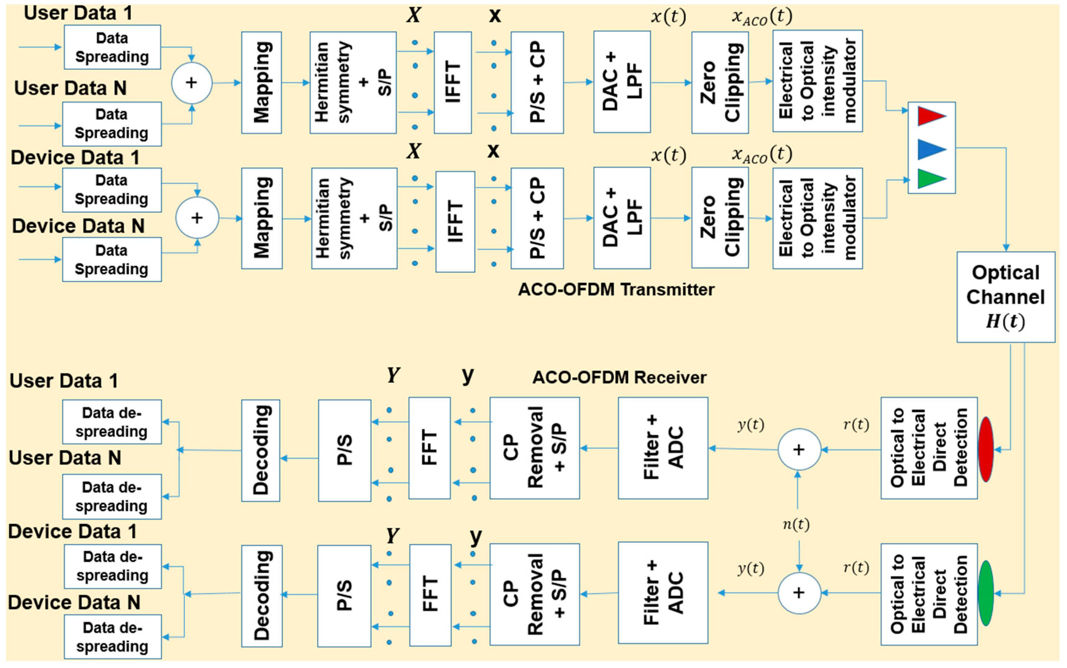
The downlink section of the system separates the data based on the type of user. A red light is used to transmit user data while green light is used for smart device data. Asymmetrically clipped optical orthogonal frequency-division multiplexing (ACO-OFDM) is used as the modulation scheme to cater to multiple users and minimize interference.
A resource allocation scheme is also implemented to efficiently assign resources during downlink transmission.
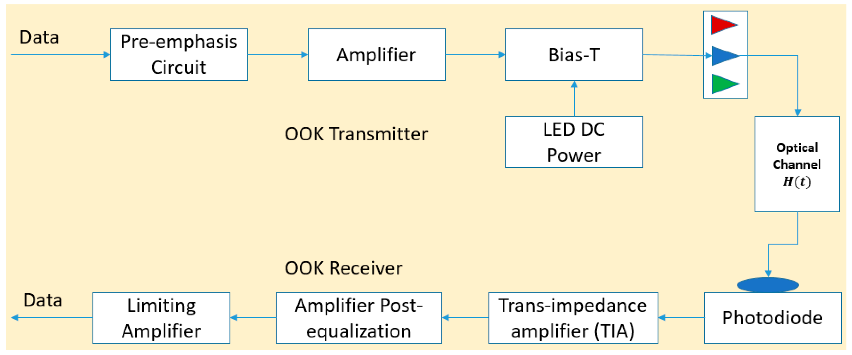
The uplink section of the system uses blue light to transmit both user and smart device data. The modulation scheme used is on-off keying (OOK).
Pulse amplitude modulation (PAM)-OOK is used to efficiently assign resources during uplink transmission.
The performance of the system is analyzed and an in-depth cost-power evaluation is provided to test for feasibility.
The proposed system is compared with other available systems such as traditional Wi-Fi and hybrid VLC-Wi-Fi implementations.
The rest of the paper is outlined as follows.
Section 2 discusses the VLC system model.
Section 3 describes in detail the proposed multi-user full-duplex VLC system designed for a smart home. In
Section 4, the resource allocation scheme is explained. In
Section 5, the cost and energy evaluation is presented. In
Section 6, results of the proposed system along with the evaluation of the cost and power consumption is discussed. In
Section 7, conclusions based on the results are provided.
2. System Model
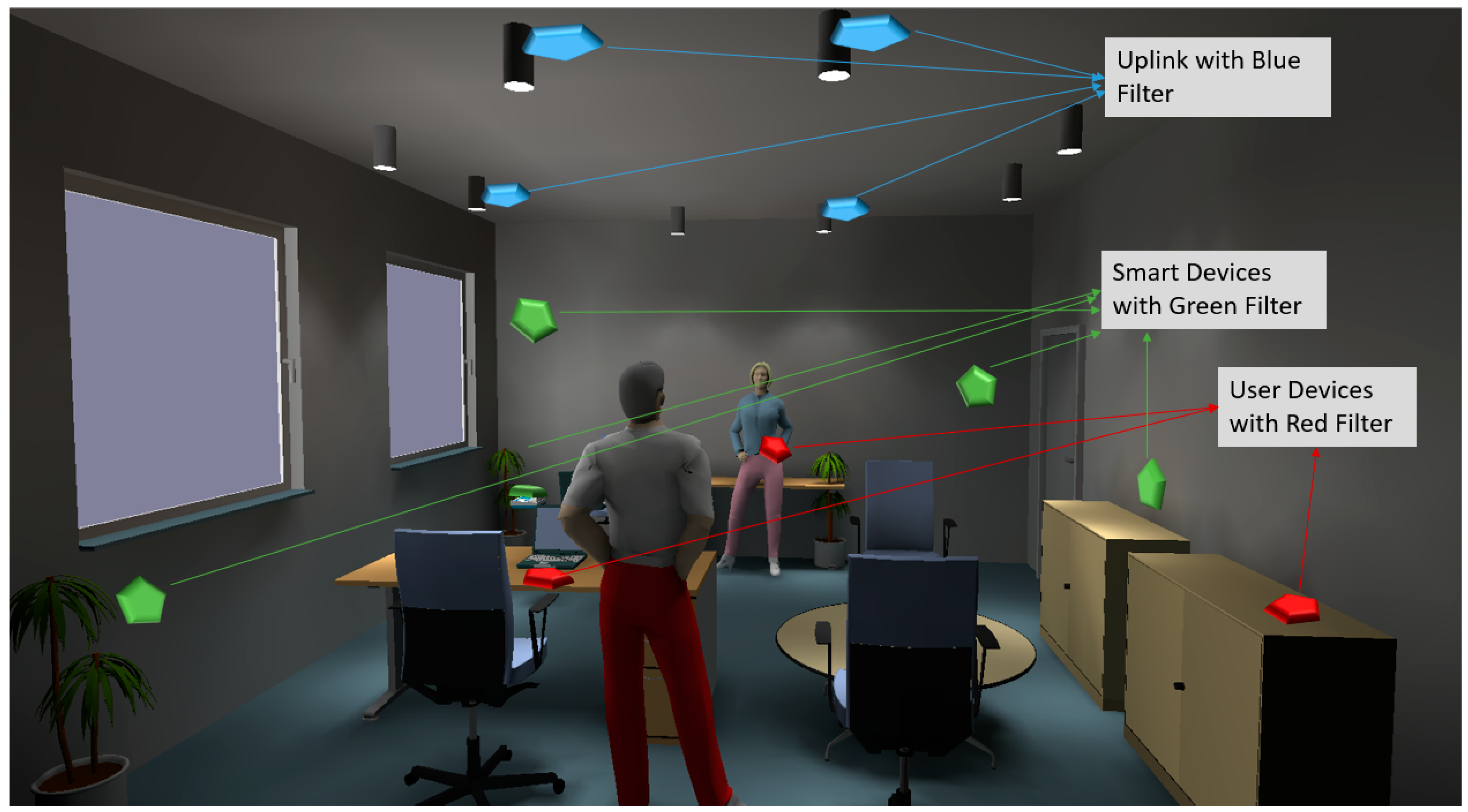
The proposed multi-user full-duplex VLC system for smart homes is shown in
Figure 1. For a particular smart home scenario, there are two types of traffic that mainly need to be taken into consideration: traffic from the user data and from smart devices. In order to account for these two types of traffic and ensure transmission occurs without any interruption, a well-defined mechanism needs to be implemented. The system can best be understood if it is broken into two sections: uplink and downlink. In this section, a simple overview of the two sections is given, followed by a more detailed description in
Section 3.
Since red-green-blue (RGB) LEDs are used in the proposed communication system, three primary channels are available for use. Red and green lights are chosen over blue light as the latter has a shorter wavelength, which means it travels a comparatively shorter distance before being scattered. The proposed system is divided into downlink and uplink sections, the majority of data used by the users and devices flows in the downlink section. To ensure that the system is robust, red and green light are used for user data and device data respectively. Unmodulated blue light is used for downlink transmission. The intensity of the three lights is controlled so that the output light is white, making it easy for the human eye to adjust to the environment such that people can continue their daily tasks without interruption. Receivers present in the downlink section are equipped with red or green optical filters so that the user data and the device data are separated. To ensure simplicity in the system design, the ACO-OFDM scheme is used to modulate the signal on the downlink channel. A brief description of ACO-OFDM is given in
Section 3.
A phosphorus LED, which is a blue LED coated with a phosphorus layer to emit white light, is used in the uplink section. Blue is chosen over red or green to avoid interference between uplink and downlink transmission. Receivers present in the uplink section are equipped with blue optical filters to receive incoming data. An OOK scheme is chosen as the uplink modulation scheme as it simplifies the system design, ensures robust performance and helps uplink devices like smartphones, which have limited power resources, to extend their battery life and efficiently utilize their computational power.
The channel and LED deployment designed for use in smart homes is given in [
28]. Results obtained in [
29] show that circular LED deployment provides best average received optical power distribution (ROPD) on the receiving plane. It performs better than traditional rectangular- and array-based deployment of LEDs on the ceiling. Additionally, the number of LEDs required in this configuration is lower than that required by traditional deployment techniques, thus reducing the power consumption and deployment cost. Moreover, it utilizes particle swarm optimization (PSO) to create room specific deployment to ensure that every room obtains the minimum luminosity required as per the IEEE 802.15.7 VLC Standard [
30]. Consequently, it has been chosen as part of our system design, as shown in
Figure 1.
4. Resource Allocation for Downlink and Uplink
The proposed system is divided into two sections, namely, downlink and uplink. In this section, the resource allocation scheme used for each is discussed. Before discussing the proposed system, let us briefly discuss the resource allocation scheme used in traditional systems, traditional Wi-Fi and hybrid VLC-Wi-Fi that we will compare the proposed system with. The resource allocation scheme used for traditional Wi-Fi is based on the latest IEEE 802.11ac Standard [
33]. The hybrid VLC-Wi-Fi system uses a cooperative load balancing scheme, which was recently introduced in [
34]. Their system is divided into two sections: downlink and uplink. The downlink section is based on a hybrid VLC and Wi-Fi system while the uplink section is based on the traditional Wi-Fi system. Cooperative load balancing that achieves proportional fairness is implemented by using a dual decomposition method. The detailed architecture of the two mentioned systems is discussed in
Section 5. In
Section 4.1 and
Section 4.2, the resource allocation scheme for the downlink section and the uplink section is described respectively.
4.1. Downlink
In this section, ACO-OFDM, which is the resource allocation scheme used in the downlink section, is discussed. The LEDs installed on the ceiling are given a unique identification (ID) number (LEDID). Since OFDM is used, each LEDID is divided into subcarriers, which are further divided into different resource blocks (RBs). The users can send their data on the RBs allocated to them. Every RB within a specific LEDID is unique; however, the same RB can be used by different LEDIDs. This can result in co-channel interference. The signal-to-interference ratio (SNIR) of a user who has been allocated an RB of an LEDID can be expressed as follows:
where
is the responsivity of the PD,
is the channel gain between the user
and the LEDID,
is the transmission power of the LEDID for a given RB, and
is the cumulative noise power. The cumulative noise power is given by:
where
,
is the ambient light intensity,
is the noise bandwidth,
is Boltzmann’s constant,
is the absolute temperature, and
is the amplifier gain.
The utility function is constructed based on the user and what type of transmission is required. Since there are two types of users present in this system, the quality of service (QoS) differs based on the type of device trying to access the system. The utility function should primarily reduce the transmission power required and cater to the needs of the user or smart device. Secondarily, it should try to extend the battery life of the associated mobile device(s), provide high data rates, and reduce interference in the multi-user environment. Each user or device has their own independent utility function based on their QoS requirements and the value of the aforementioned parameters. The utility function that accounts for the above parameters is given by:
where
is the number of users served by the LED,
is the bandwidth available, and
is the efficiency function. The efficiency function represents the probability of a successful packet transmission.
The proposed algorithm is called non-cooperative resource allocation (NRA) and is defined in
Table 1. It is decentralized and determines the user or device LEDID selection and resource allocation in a distributed manner. It is iterative and has a low complexity. It consists of two parts. The first part is the selection of the LEDID. This is based on the maximum gain selection (MGS) policy. The second part is the resource allocation where the RBs are allocated depending on their QoS requirements. The second part is iterative and it will keep repeating the algorithm until it converges to a unique solution. The user is assumed to have perfect knowledge of the channel matrix
, i.e., the channel between the user/device and the LED.
4.2. Uplink
For the uplink section, PAM-OOK, a fairly simple resource allocation scheme, is deployed. OOK allows the users to be separated on the basis of their amplitudes. A lookup table is created which has all the information about the users/devices. In the simulations conducted, there were a minimum of 15 user/devices and a maximum of 30 user/devices. Consequently, a 5-bit encoder was sufficient to allocate a unique amplitude to each user/device. Using PAM, each user is assigned a different amplitude level and using the lookup table the receiver is able to differentiate between different users/devices. The composite signal is transmitted to the uplink section and the receiver decodes the signal and separates the user data using the lookup table. In this way, a low-cost multi-user PAM-OOK is implemented which can cater up to 32 users and deliver acceptable performance for full-duplex multi-user VLC system.
5. Cost and Energy Evaluation
To deploy a multi-user full-duplex VLC system in the market, it must be both cost and power efficient. The proposed system is compared with two other systems that are commercially available and have been widely reviewed in the existing literature. The first system is the traditional Wi-Fi system that is currently one of the most widely used wireless systems in the world. The second system is the hybrid VLC-Wi-Fi system that is currently being widely studied and researched [
34]. In this system, the downlink transmission can either be carried out using VLC or Wi-Fi but the uplink transmission is always based on Wi-Fi technology. This design was aimed at resolving issues that affect uplink transmission in VLC systems and ensures uninterrupted connection for the user or device. In this section, we compare the proposed system to the aforementioned systems and present analysis of the simulations results in
Section 6.
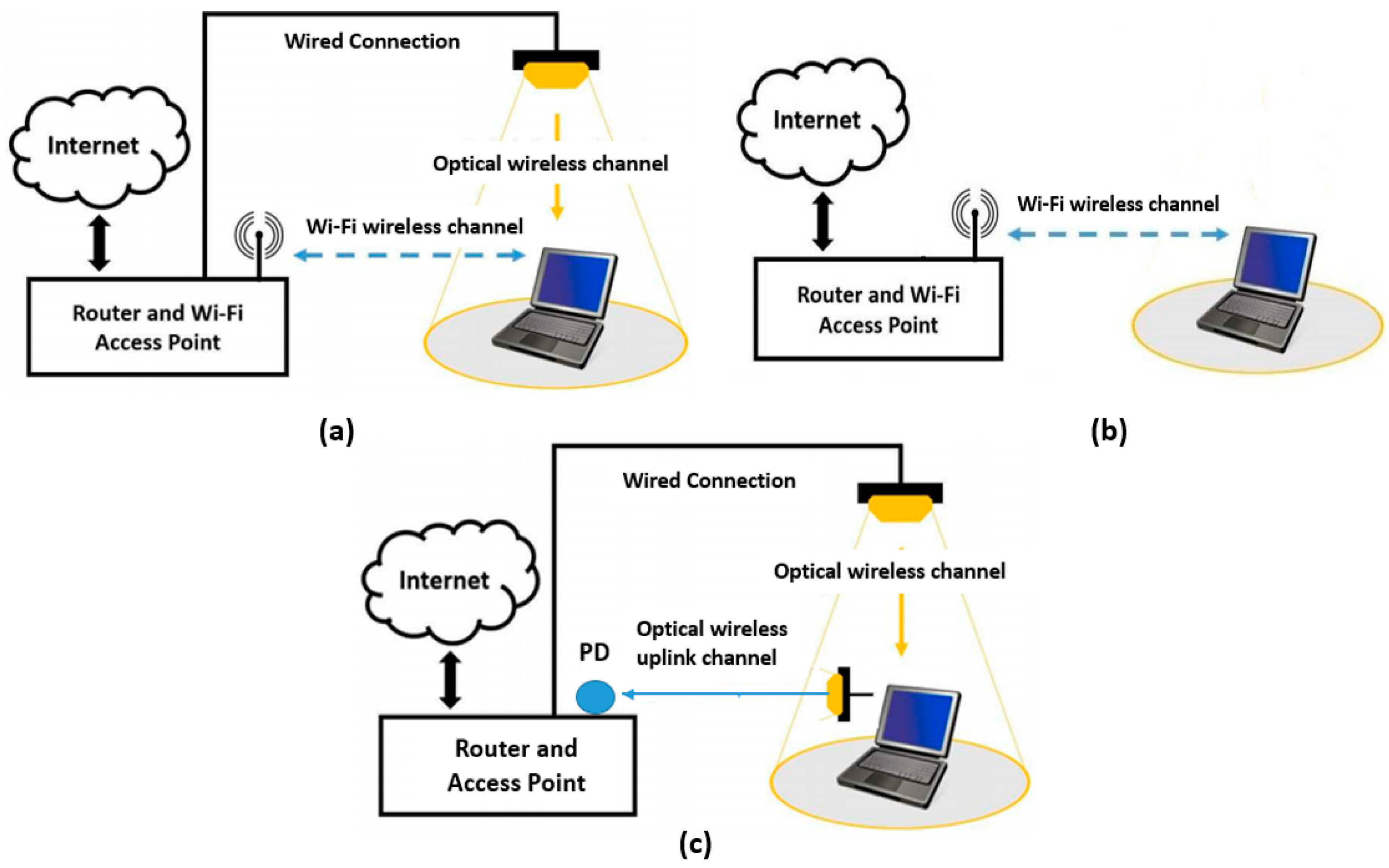
The architecture of the two systems is described as follows. The simple Wi-Fi system consists of a router with a wireless access point. The router is connected to the wide area network (WAN) and using RF radiation, transmits and receives data. A simple Wi-Fi system is shown in
Figure 4a. On the other hand, a hybrid VLC-Wi-Fi system utilizes both technologies to achieve a robust system performance. The downlink transmission can be based either on VLC or Wi-Fi, while the uplink transmission is based on Wi-Fi. The hybrid system is depicted in
Figure 4b.
Figure 4c shows the depiction of the proposed system.
In order to implement a VLC system, the use of signal processing unit (SPU) is essential. The nature and scope of the signal processing required depends on the size of the home and the number of users. This study presents different types of SPUs, whose architecture differ based on processing power, cost, and power consumption. Since VLC systems are yet to be commercially available, unlike Wi-Fi systems, the initial installation cost that is included in the simulation and the results is an approximate value. As is the case when any new product is launched, the initial equipment price will be high when VLC is launched but as it becomes more common, the price will also decrease substantially. This is similar to what was observed when Wi-Fi was initially introduced in 1999.
In this study, the SPUs with different architectures are used and comparatively studied. The architecture of SPU can differ with respect to the number of cores and general-purpose input-output (GPIO) registers it offers. This can significantly affect the processing speed and power consumption of the whole system. As the number of cores increase, the performance of the unit increases but the cost and power consumed also increase and vice-versa. Thus, the SPU has to be carefully designed to ensure optimum balance.
Table 2 presents several SPU architectures with different cost, power, and processing power. Since this paper is related to smart home technologies, architecture 1 will be used for simulation purposes. Both hybrid and full-duplex VLC systems use the same architecture and the results and analysis are given in
Section 6.
As per
Table 2, architecture 1 has one core and four GPIO registers. This is the most basic, low cost, and power-efficient processing unit. Since the number of sub-channels is not yet defined in the VLC standard, it is safe to assume that there are 32 sub-channels. Therefore, with the architecture 1 processing unit,
users and devices can be accommodated. This is more than enough for a smart home application.
Table 3 provides the power consumption of an average American household. The table only shows devices that have the potential to use VLC in the future.
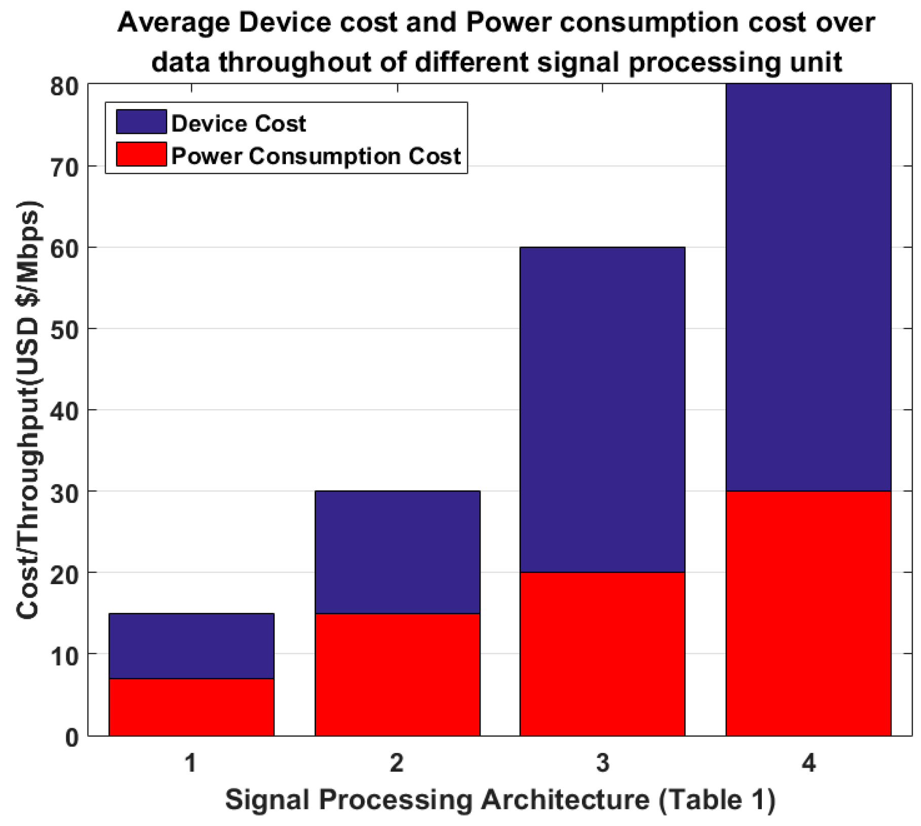
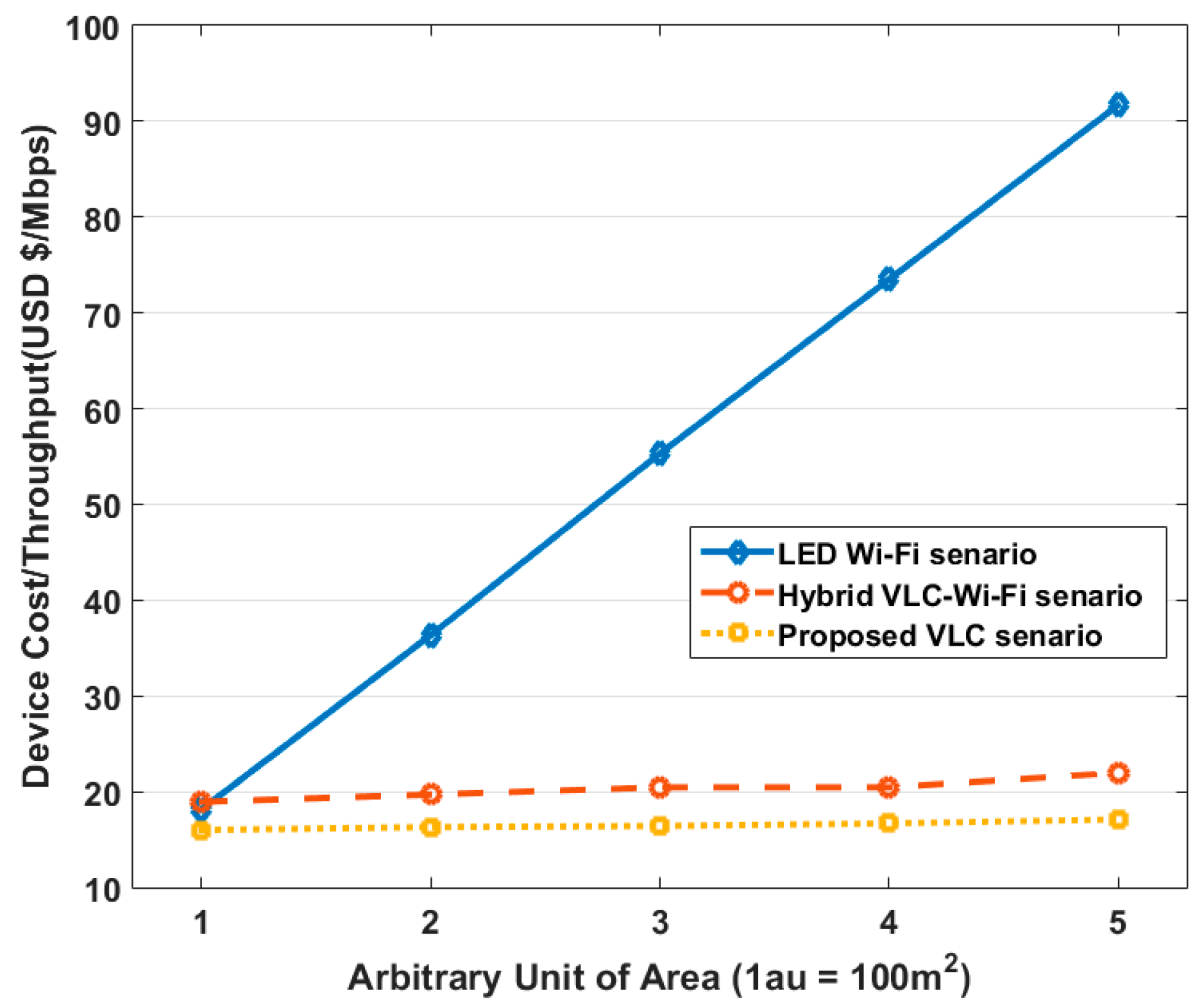
The performance evaluation of the three systems in terms of device cost and power consumption against data throughput is carried out. No commercial VLC products are currently available, which makes a comparison on the basis of cost and power consumption difficult. Consequently, we develop a criterion to illustrate the potential comparison between the three systems. For the hybrid VLC-Wi-Fi system and the proposed full-duplex VLC system, the cost of the SPU, which is typically used for commercial telecommunication system implementation and is based on the Texas Instrument digital signal processing (DSP) board series C6000, is approximated [
34]. The computation of the device cost and power consumption includes the cost of maintenance and electricity used in the long run. The indoor VLC environment simulation model is taken from [
29]. Other simulation parameters are discussed in
Section 6.
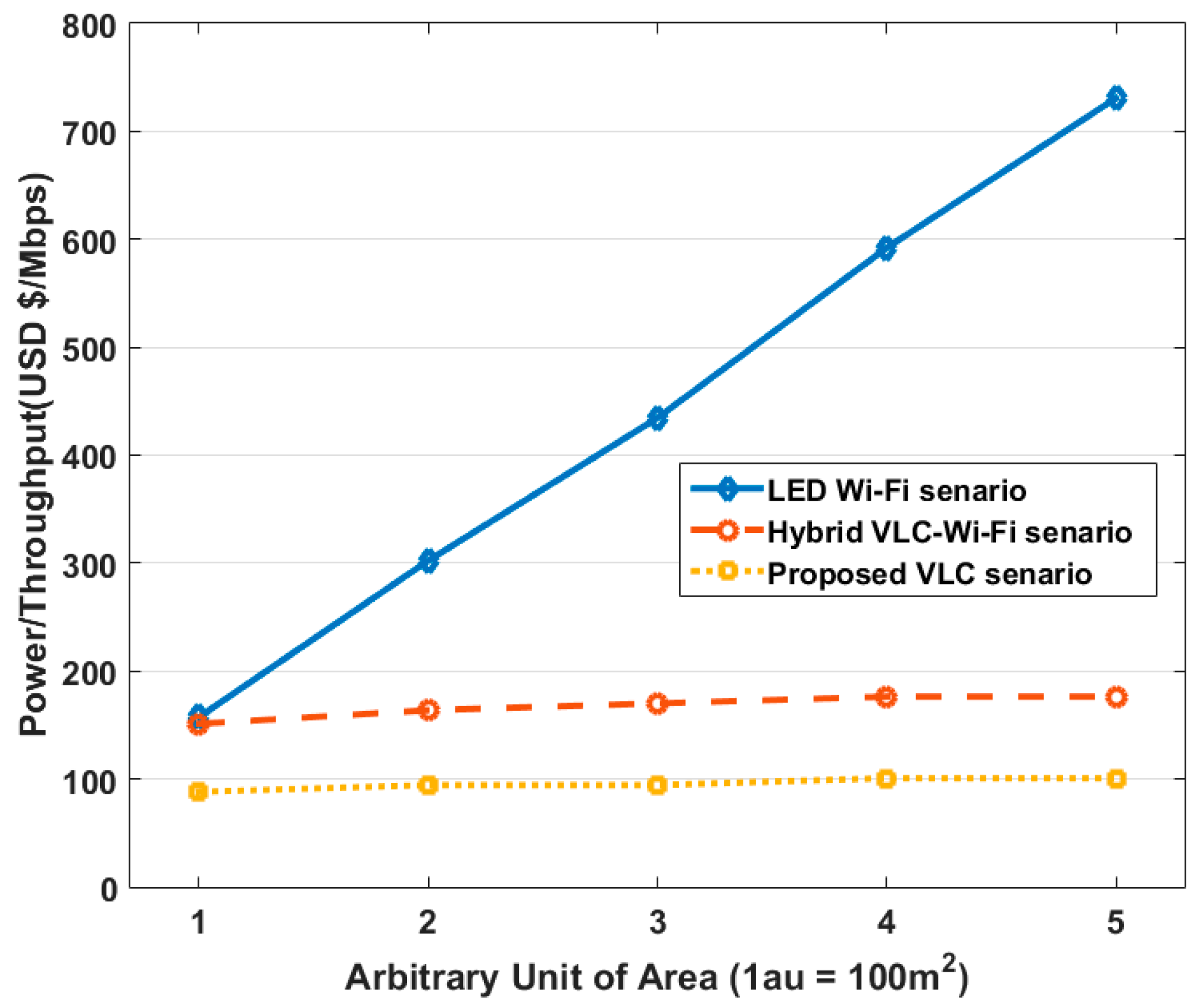
The calculation of the cost and power consumption of the first system, which uses simple LED lighting with Wi-Fi, is done using the following equations:
In the above equations, is the number of LED lights replaced during the length of the simulation, is the total number of LEDs used in a specific room, is the cost of LEDs used, is the cost of Wi-Fi equipment and the internet connection used, is the power consumption of the LEDs, and is the power consumption of both the Wi-Fi access point and the router.
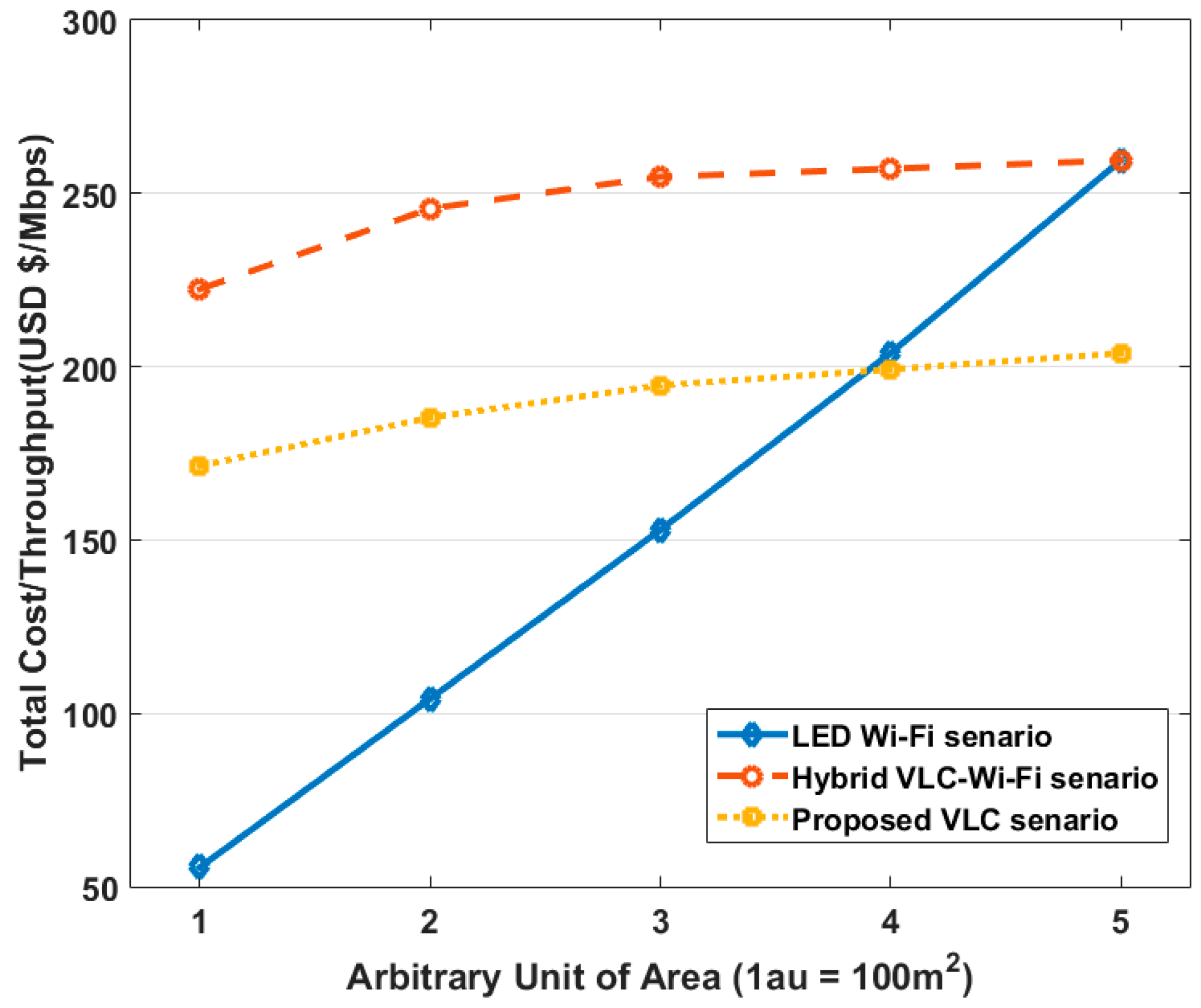
The calculation of the cost and power consumption of the second system, which is a hybrid VLC-Wi-Fi system, is done using the following equations:
In the above equations, is the cost of the SPU and is the power consumed during the operation of the SPU. Here, the is multiplied by the number of LEDs used because the LEDs are connected to the GPIO register of the SPU and consequently, will draw power according to the number of LEDs that are attached. The method of connecting the LEDs to the GPIO register can vary. For example, they can be connected such that each GPIO will entertain one LED, which is an expensive solution. Alternatively, an array of LED lights that serves one room can be connected to a specific GPIO, which would allow the whole home to be covered using only one SPU. As mentioned earlier, if there are 32 VLC sub-carriers, then by using a simple one-core and four GPIO register-based SPU, a total of 128 users or devices or both can be entertained.
The calculation of the third system, which is the proposed full-duplex VLC system, can be done using the following equations:
The main difference between the second and the third system is the removal of the Wi-Fi device. The analysis of the simulation is given in
Section 6.


