4.1. The Security Thread
The evolution on the remote control of the electrical distribution grids could give back undesirable vulnerabilities if the architecture is not correctly secured. Smart grid network control and monitoring are very important features for providing distributed energy generation and storage, QoS and security. Smart grids link many distinct types of devices (IEDs) demanding very different QoS levels over different physical media. Obviously, this kind of data network is not exempt from the growing needs of cyber security. In addition, availability and secured communications are also crucial for the proper network operation [
25], which drives practitioners to consider active network management (ANM) techniques to coordinate the whole communication network.
In addition to this, the smart grid relies on sensors, actuators and a management network, usually controlled by supervisory control and data acquisition systems (SCADA), which are used to control and supervise industrial processes from a computer. That is to say, SCADA systems control items in the physical world through computer systems. This is one of the points in which the main security concern of smart grids relies. Some recent cases have demonstrated the critical relevance of it.
One of the most famous cases in this matter is Stuxnet [
26], a very complex worm and Trojan discovered in June 2010 that attacked the Iranian nuclear enrichment program. Its code used seven different mechanisms to expand itself, mainly exploiting 0-day vulnerabilities. It achieved the destruction of about a thousand nuclear centrifuges by changing the behavior of the actuators while telling the sensors that everything was good.
A year later, in September 2011, a new Trojan called DuQu was discovered presenting a very similar behavior to Stuxnet so it is believed that the two worms were related [
27].
In 2013, Iran hacked US Energy Companies (oil, gas and power) and was able to gain access to control-system software and was also accused of launching DDoS (distributed denial of service) to US banks [
28].
On 23 December 2015, hundreds of thousands of homes in the Ivano-Frankivsk region of Ukraine were left without electricity as a result of an attack [
29]. Hackers were able to successfully compromise information systems of three energy distribution companies of the country and temporarily disrupt electricity supply to the end consumers.
Cyberspace is defined as “an operational domain whose distinctive and unique character is framed by the use of electronics and the electromagnetic spectrum to create, store, modify, exchange and exploit information via interconnected ICT-based systems and their associated infrastructures” [
30]. Thus, cyber warfare is the kind of war that happens in that space in contrast with the traditional kinetic warfare where physical weapons are used. Smart grids have become a clear potential target of cyber warfare considering that nowadays almost everything runs on electrical power and therefore potentially causing outages or, even worse, causing damage especially in some kinds of power plants (e.g., hydroelectric, nuclear, etc.).
Regarding cyber security standards, many of the existing ones have to be taken into account in the smart grid as is highlighted in NISTIR 7628 [
31], where they are listed and commented. A relevant one among them is ISO-IEC62351-6 [
24] because it is the cyber security standard of reference for IEC 61850 and, thus, for the smart grid. NISTIR 7628 gives guidelines for cyber security implementation in the smart grid and provides a logical security architecture of general nature. Significantly, it contains interesting considerations regarding the use of authentication certificates and secret keys management.
The state of the art regarding security in the smart grid is in fact defined in the mentioned IEC 62351-6 standard, which basically applies security at transport layer (TLS1.0 [
32] with some restrictions) and upper layer communication protocols. It could be argued that protecting the transport layer could be enough since this may provide confidentiality, integrity and device authentication for user data and because many commercial systems rely on protecting systems just like this. However, protecting the smart grid only at the transport layer leaves the network and its links open to cyber security attacks such as DoS, which can produce an eavesdropping of network management messages and ban the users from accessing the service. This fact is not aligned with the high reliability feature that is required in the smart grid [
33]. For this reason, the smart grid really urges multilevel security, even above the transport layer [
1,
2]. Moreover, some smart grid applications (e.g., smart metering data management) can also require additional data anonymization and data encryption services at the edges that could be added when needed, for preserving consumers’ privacy. A table summarizing the most important security issues that can affect the proposed data storage infrastructure for the smart grid was previously published in [
8]. It was developed by gathering this information from several sources and putting together the experience of academia and industry experts from utilities and telco operators’ managers.
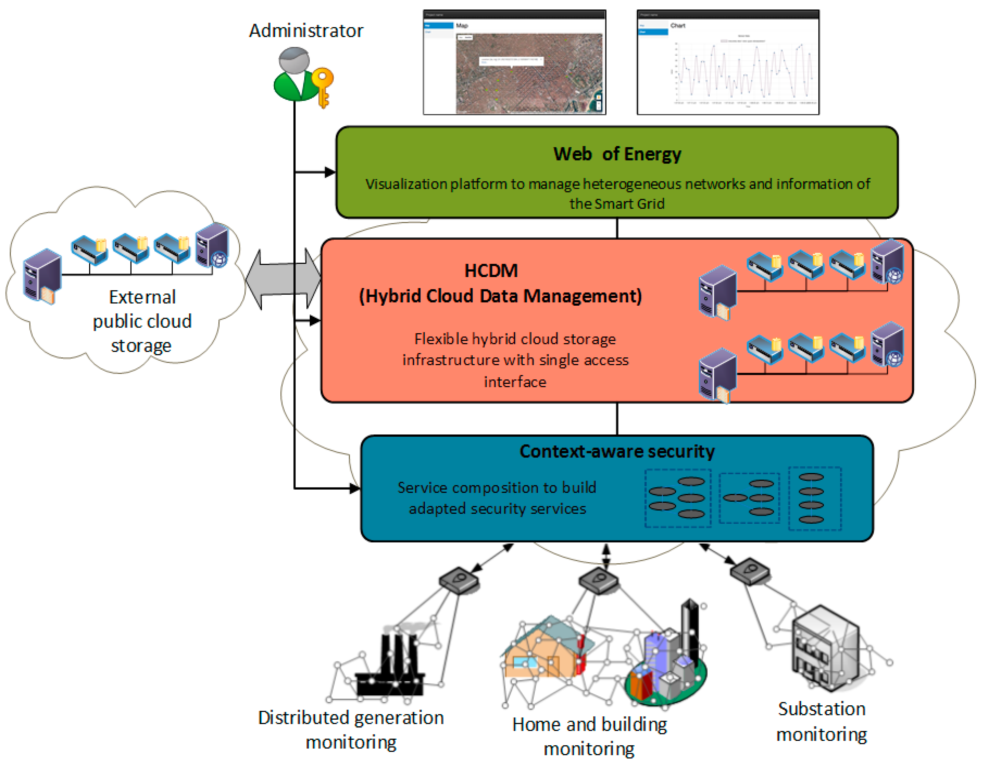
To face this challenge and secure the smart grid, the proposed security system is designed in a way that it is really deployable and operative, that balances the many and sometimes conflicting security goals of the different actors and subsystems and accommodates a large and dynamic set of security mechanisms. This is done by creating an entity in which to concentrate the distributed agents that provide service to the smart grid among which the security server and repository (
Figure 1).
As it can be seen, all the concerns revolve around the efficient adaptation of the security mechanisms to the specific requirements of the smart grid function to be deployed. Therefore, a context-aware smart grid management broker has to be placed in different locations of the SDU and work coordinately in order to provide the adapted security mechanisms when and where needed. As an example of this dynamic security configuration, a use case focused on flexible smart metering security is shown in the following section.
4.2. Securing Smart Metering Through Service Composition
This section summarizes the extension of service composition techniques in order to manage flexible smart grid applications. More concretely, it develops the methodology around a proof-of-concept use case that focuses on the securitization of the advanced metering infrastructure of the smart grid. The obtained results can be extended to the whole smart grid and are showcased in real and modern applications.
As stated before, the smart metering represents only a set of the smart grid solutions, but it is the part that has already been more regulated, deployed and tested around the world. Advanced metering infrastructure (AMI) consists of smart meters, data management, communication network and applications. AMI is one of the three main anchors of smart grids along with distributed energy resources (DER) and advanced distributed automation (ADA). Smart metering is usually implemented using automatic meter reading (AMR), a technology that automatically gathers data from energy, gas and water metering devices and transfers it to the central office in order to analyze it for billing or demand side management purposes. Data is read remotely, without the need to physically access the meter. AMR systems are made up of three basic components to be secured end to end: the meter, the central office and the communication systems. AMR includes mobile technologies, based on radio frequency, transmission over the electric cables (power line), or telephonic platforms (wired or wireless) [
3,
15].
The deployed prototype is focused on collecting smart meter and RTU data, encrypting them and saving them in some place (the cloud, a concentrator, the IEDs, etc.) in a way that the authorized actors can work with the data without having access to user specific data, preserving their customers’ anonymity and protecting them from malicious attacks.
First of all, in order to determine the security requirements of the smart metering function, it has been of great importance to follow the guidelines for smart grid cyber security [
31] developed by the National Institute of Standards and Technology (NIST), because of its high detailed description of requirements and elements that must be taken into account when deploying a smart grid. Since this research targets to secure smart metering as a first approach, a limited set of requirements have been selected from among over 200 entries in [
31], considering those that affect directly or indirectly to the smart metering use case. Once the requirements have been set up, a chart (
Table 2) has been developed with the cybersecurity requirements [
34] on one axis and the technologies that can be used to meet the requirements on the other axis. The different technologies are graded (from 5 when it totally applies, to 0 when it does not apply), depending on the level of support to the requirement. They were also selected based on the authors experience from [
8,
9], besides an exhaustive review of the literature about smart grid security and specify which secured-ICT technology can meet more accurately the requirements.
In addition, the conclusions extracted from the experience acquired in those projects that have guided this work have helped us to define the following rules in the design of cyber security solutions for smart grid:
To rely as much as possible on proven existing standards, only complementing them when strictly necessary. This comes from the evidence that the first versions of most standards contained serious vulnerabilities.
To choose the most adequate option from these standards for the specific smart grid case (see
Table 2).
To place cyber security services as close as needed to the sensing and actuation points to improve latency and reliability of applications. In fact, these capabilities aligned to fog computing trend can be based on service composition paradigm by placing them in the cyber security server and repository contained in the IEDs.
To use a common coordinated cyber security data repository for all the involved technologies.
To distribute this repository, either as a whole or partially, in the cloud, although having also a central repository located elsewhere. The central cyber security repository is replicated so that, in case of disconnection, the system continues to work for some time even allowing the inclusion of new devices and functions.
To define cyber security metrics to feed the context-aware system to enable improved system management.
To use, whenever feasible, authentication based on certificates.
Many examples of smart metering use cases that should fulfill the security requirements of
Table 2 can be defined, such as the installation process of a smart meter, reading the power consumption, firmware updating, system monitoring, maintenance processes, fraud avoiding, etc. Aiming at just giving a proof-of-concept demonstration of some of these benefits that service composition and SDN could bring into smart grid, a basic use case was designed on securing the smart metering in a software defined utility environment [
8].
Combining SDN and service composition becomes especially powerful for the secure self-maintenance of networks, which represents a very important characteristic for the development of smart grids. They could be applied at different segments of the electrical distribution grid implementing easy and fast-to-deploy intelligent solutions.
The focus on the service composition interoperable standalone modules, which can be invoked or dropped on demand, leads to considerable cheap solutions in the field of smart grids and presents a solution that could be integrated incrementally. Moreover, it allows system architects to create flexible solutions that could be modified and evolved according to eventual new needs. Furthermore, the modularization of smart grid functionalities and encapsulation into self-contained services facilitate the distribution of the smart grid intelligence, approaching the reasoning and decision process and helping to handle its critical constraints of latency on fault reaction.
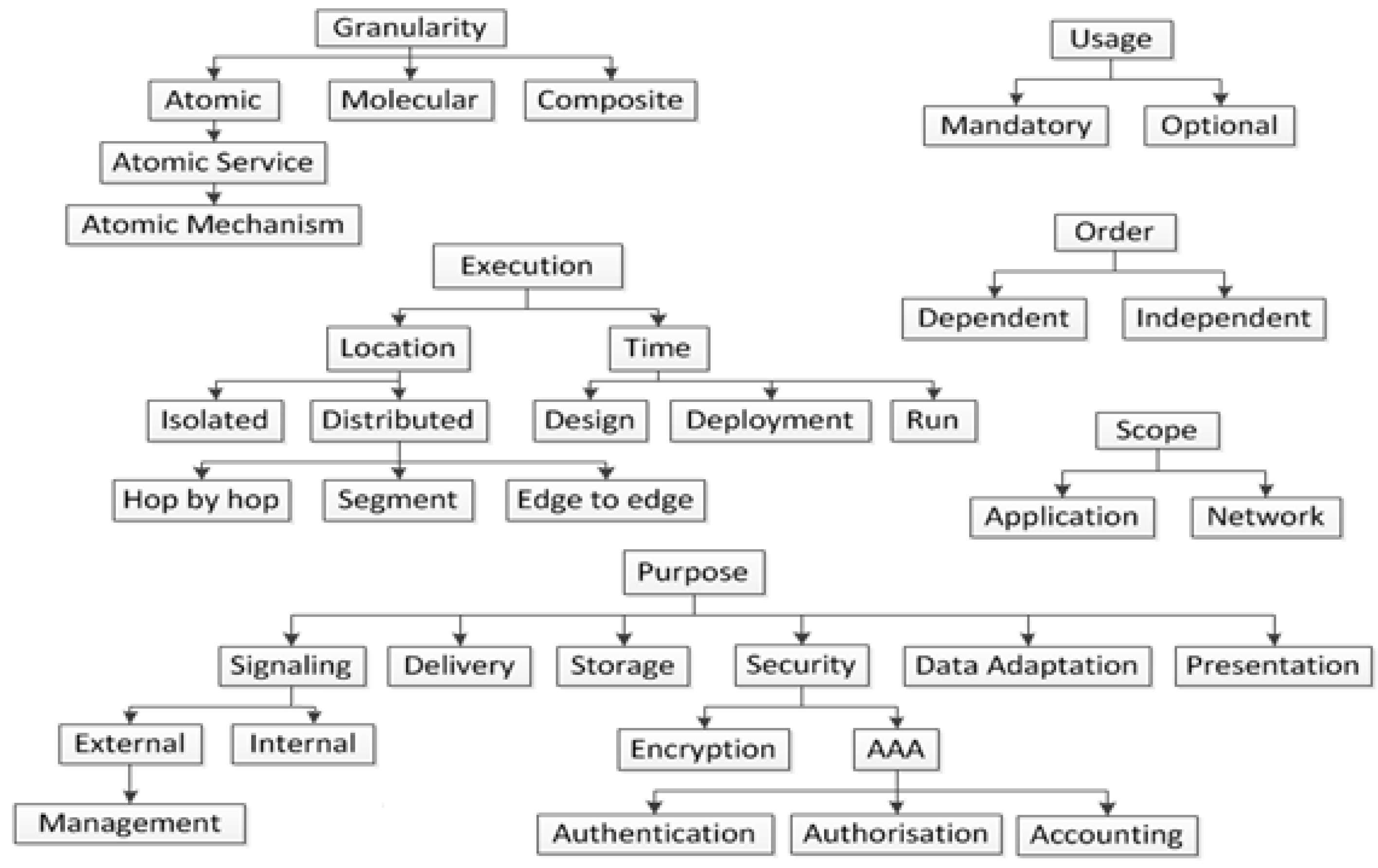
In this regard, the authors have extended the work conducted in [
6] and present a new taxonomy of services (
Figure 5) for AMI security in this paper. This taxonomy classifies services into six different generic parameters: “Granularity”, “Execution”, “Scope” (application/network), “Purpose”, “Usage” (mandatory/optional) and “Order” (dependent/independent), following the criteria selected in [
6] and defining new sub-criteria based on the general and security requirements of a smart metering management [
2,
9,
31,
35]. All these criteria can be applied generically to any smart grid service, although the options shown in
Figure 5 for “Purpose” criteria are limited to smart metering. Afterwards, the selected modules for smart metering are classified according to this taxonomy (
Table 3).
The one by one definition and classification of the modules can guide the service composition design process done of composite services and the placement of the different modules in specific physical or logical locations of the smart grid. For example, considering the description of some security modules such as AAA (authentication, authorization and accounting) module, its execution location could be in a specific segment or end-to-end, while encryption or decryption modules are isolated modules that could be placed in a specific location of the network. This fact can help the reasoning of the administrator or the specification of automation processes for building and deploying composite services automatically in a multilayered scheme. However, some characteristics are intrinsically related to the functionality offered by the composite service to the end-user, such as the atomic service usage (optional or mandatory) or the order of them inside the workflow (dependent or independent) and, thus, they can only be completely defined when building the composition.
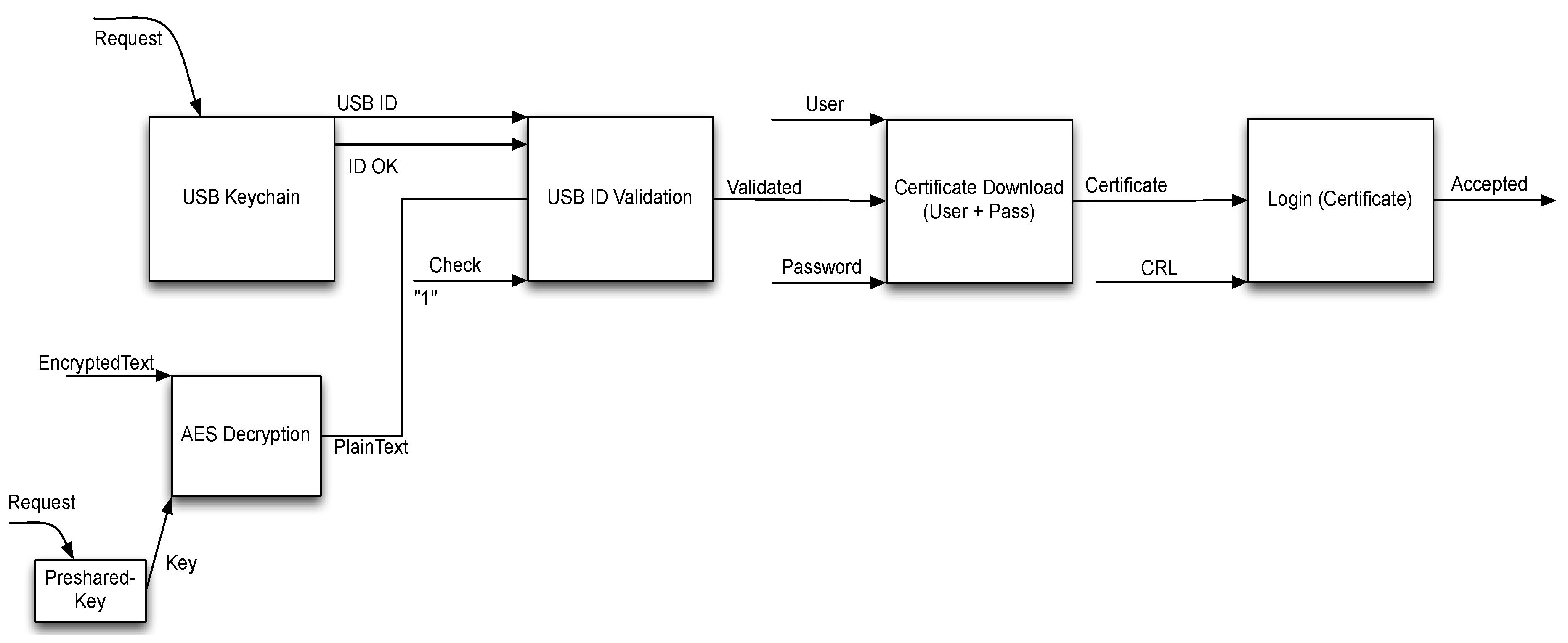
4.4. Workflow Example
Finally, the modules have to be joined to create the whole workflow. As it has been described before, this process allows the smart meter function to be enrolled into the smart grid system. In order to do so, the whole process is being carried out in some steps (
Figure 6). A request to the USB device is made, then both the signal saying that the USB is still connected and the ID of the USB itself is sent to the next module that checks whether the ID is valid or not, using the information in plain text received from the AES decryption module. At the same time, this module receives the decryption key from another module. Then, if this step is completed successfully, the technician must insert his username and password. Then, the certificate is downloaded and once checked with the certificate revocation List, the smart meter can successfully login to the smart grid network.
However, the importance of this process is not the process itself but its modularized design based on service composition, development and deployment. That is to say, the main importance is the great flexibility provided by this way of working. It is very different to current-day straightforward deployments by procuring to the system architect a reusable design, a function virtualization and a chance to cloud computing deployment. If this process does not suit the utility’s needs it can be easily changed, modules can be quickly swapped for others or even removed to simplify the process. The greatness comes when this technique is combined with some kind of intelligent middleware that set the policies and build the workflows autonomously (orchestrator) [
36]. The orchestrator could even learn and make decisions based on the status of the network [
1]. Another interesting characteristic is that it does not depend on how the modules are implemented. As long as the input and output interfaces are well-defined, the module interoperability is fixed. Thus, it should also help to avoid any vendor lock-in and to foster the interoperability and reusability of the systems.
4.5. Interfaces Definition
Usually, service modules like the ones presented in this work are expressed by means of well-defined interfaces that hide their implementation (in order to maintain them loose-coupled in the service composition process) that could be coded in different logic or development languages. In this case, the option of using web services description language (WSDL) [
37] was selected to exemplify and deploy this use case. WSDL is the most extended language used by web-services description, and offered a good solution for an easy and fast definition of the services’ interfaces, besides bringing a standardized and well-known language easy to integrate with other service frameworks like OSGi [
38]. Definition of services used in [
6,
7] was adapted for network services. However, it was defined generic to be adapted to application cases as well, as this one. Therefore, specific or more complex definitions can be used in the future, to completely define and deploy the services on demand, placing and invoking or dropping them on one device or another. The following list enumerates the basic interfaces that each one of the services defined in
Section 4.3 can include:
Types: In this field, the variables are defined using a simple name and type nomenclature.
Interface name: Contains the name of the interface.
Fault_name: Name of the attribute generated when an error appears.
Operation_name: Indicates the name of the operation. It must be unique per interface. It also contains the pattern that usually is “in-out” or “in-only” and defines how the data is exchanged and style (non-mandatory).
In_msgLabel: Defines the name and format of inputs.
Out_msgLabel: Defines the name and format of outputs.
Out_fault: Associates the output error with the operation.
At the end, the number and quality of the resulting workflows are limited by the compatibility and exchangeability of the individual service modules. Therefore, the adequate planning of the interfaces is highly relevant since it will define how the modules can communicate between each other.


