1. Introduction
In mobile robot applications, battery charging is seen as a bottleneck problem. Wireless power transfer (WPT) technology can provide a flexible, safe, and convenient way to power the robot [
1,
2,
3,
4,
5,
6]. WPT technology utilizes a magnetic field to transfer energy between two loosely-coupled coils, which can enhance the mobility and reliability of the robots and operate under harsh environments such as humid, high-temperature, dirty, and corrosive environment [
7,
8,
9].
With the rapid development of robotic technology, increasing applications require fast charging. Wireless power transfer capacity should be increased accordingly to meet fast charging requirement. Current research on power capacity improvement can be classified by three groups: the first group of methods utilize composite resonant network to increase system energy absorption ability. The composite resonant network can also provide a system with better anti-frequency drifting ability. LCL (inductor capacitor inductor), CLC (capacitor inductor capacitor) and LCC (inductor capacitor capacitor) composite network are commonly used for the purpose. References [
10,
11] proposed a WPT system based on an LCL resonant network, which improves the capacity of the resonant tank and accomplishes constant current. References [
12,
13] used an LCC compensation network in dynamic wireless charging for system optimization. However, the composite resonant network will yield a high system order and slow down system response. Moreover, it may increase the risk of frequency bifurcation due to the existence of more soft switching running points. The second group of methods utilize multi-phase converter and matrix converter to increase high-power conversion ability [
14,
15], which can reduce the stress of switches at the same time. However, it has a complex circuit structure and the resonant tank still needs to be subjected to excessive current and voltage stress in high-power application. Reference [
16] presented a novel dynamic WPT system by combining the multi-parallel system with an LCC composite resonant network, which minimized the electromagnetic interference (EMI) and reduced the system’s power loss. Moreover, for a high-order system (especially parallel multi-inverter), the response of the system is slow and the power regulation is relatively difficult. The third group of methods utilize an additional energy storage and emission circuit to increase the energy storage ability. It is realized by energy injection and emission control to regulate power capacity [
17]. In the above methods, in order to achieve high power capacity, high voltage and current stresses will appear in the power conversion and resonant tank system. It will directly increase the cost of whole system and may bring the risk of system failure. Therefore, it is necessary to propose a method to improve system power capacity without increasing voltage or current stress.
In high-power applications of WPT technology, a single excitation unit will meet many difficulties in application, including limited power transfer capacity and high voltage and current stress. The dual excitation units (DEU)-WPT approach with dual excitation units will greatly improve the power transfer capacity and reduce the voltage and current stress at the same time. Furthermore, the output power can be flexibly regulated by controlling the phase-shift angle between dual excitation units. Output characteristics under mutual inductance and load variation are given. Through the specific analysis, the proposed system has a better robust characteristic. Finally, the simulation and experimental results verify the feasibility.
2. Design of DEU-WPT System
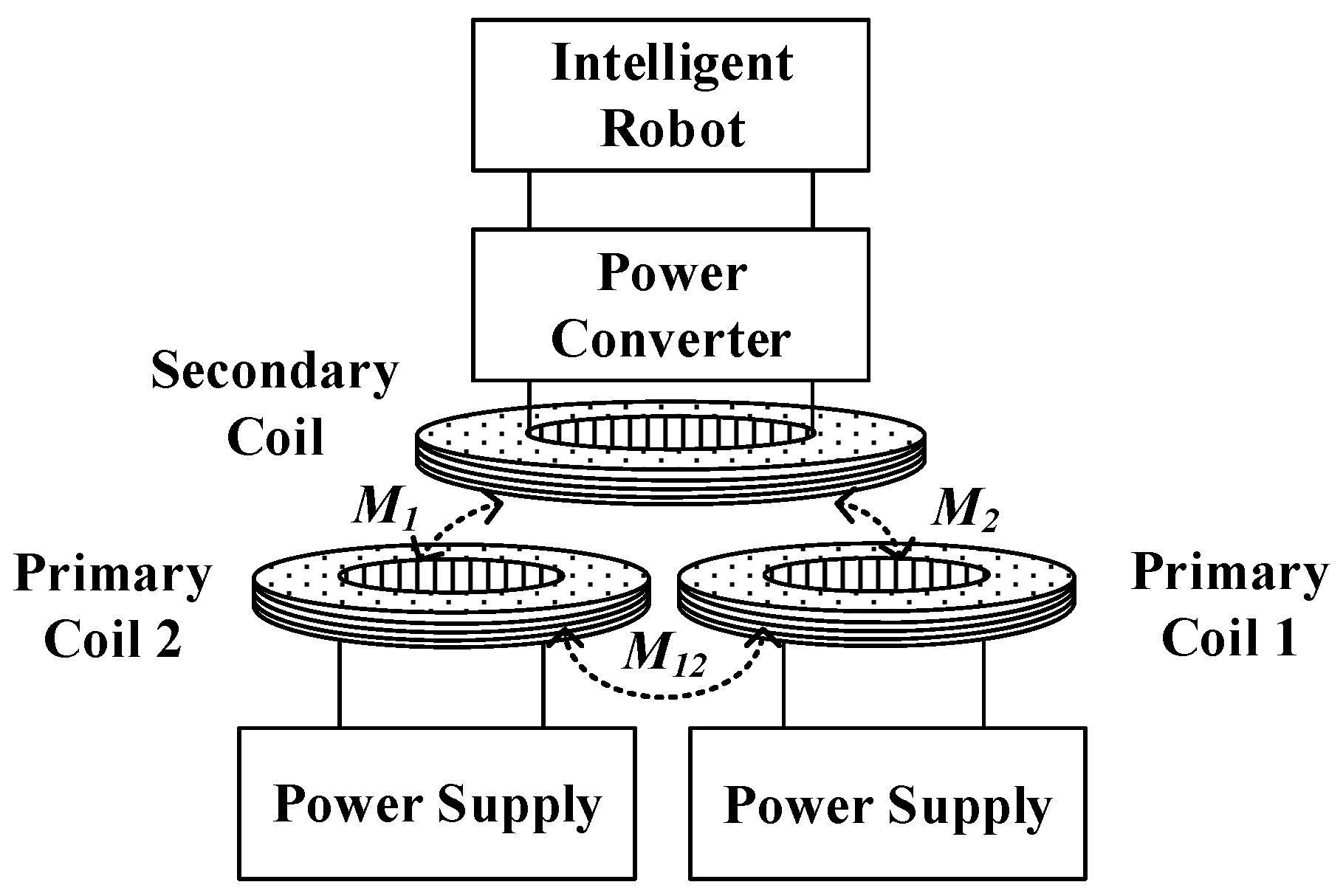
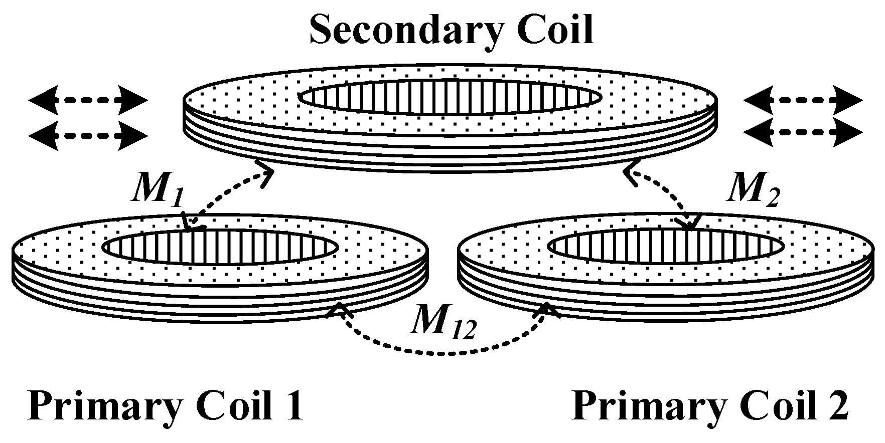
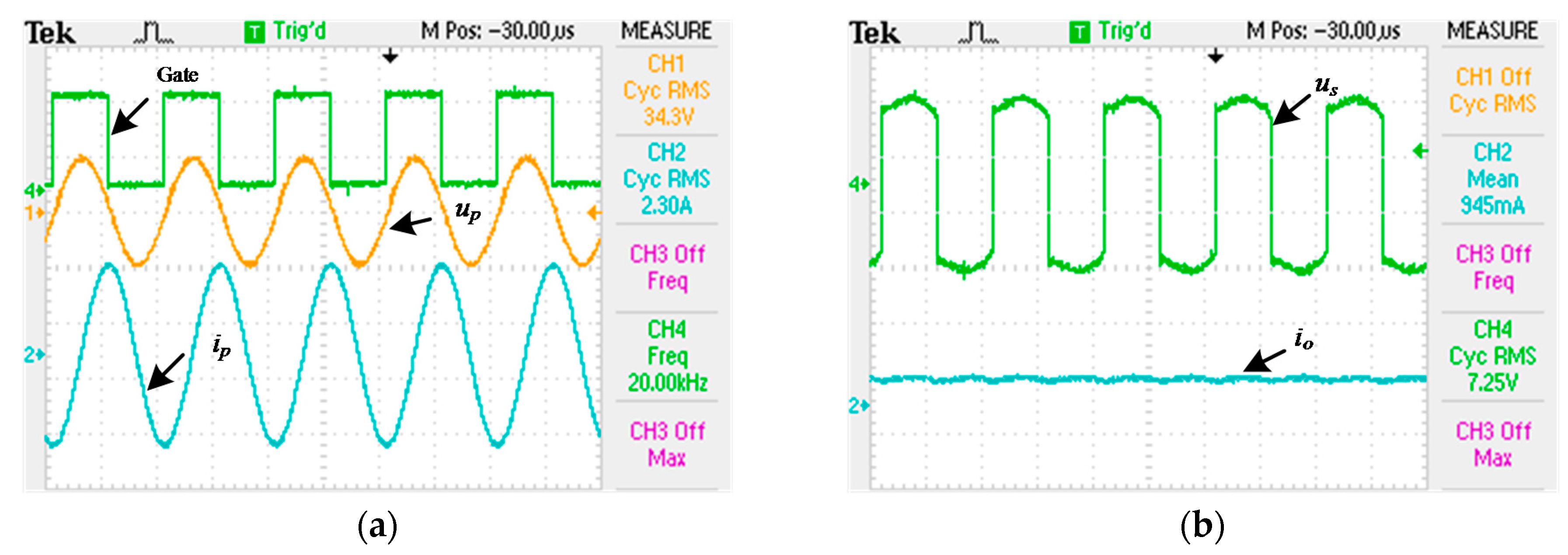
The structure of the system based on the dual excitation unit is shown in
Figure 1. Compared with the traditional WPT topology, an excitation unit is added, and each unit is connected by a full bridge inverter circuit. The coil magnetic field is generated and enhanced by the alternating current of the dual track. Considering the parallel compensation of secondary winding will have the phenomenon of frequency drifting, and cross-coupling of primary side coils in DEU-WPT will make the system impedance matching more complicated; in order to reduce the complexity of the system, the series compensation of secondary winding is adopted. Moreover, primary coils which use parallel compensation are the optimal choice when both high transfer efficiency and power output power are required, and specific analysis will be discussed in
Section 3 and
Section 5. Because the system is a current-mode WPT, it is represented by a large inductance
Ldc in series with the DC (Direct Current) power supply. Among them,
M1,
M2 represent the mutual inductance between each primary coil and secondary coil, and
M12 is the cross-coupling inductance. The value of the mutual inductance will have impacts on the output power and efficiency of the system.
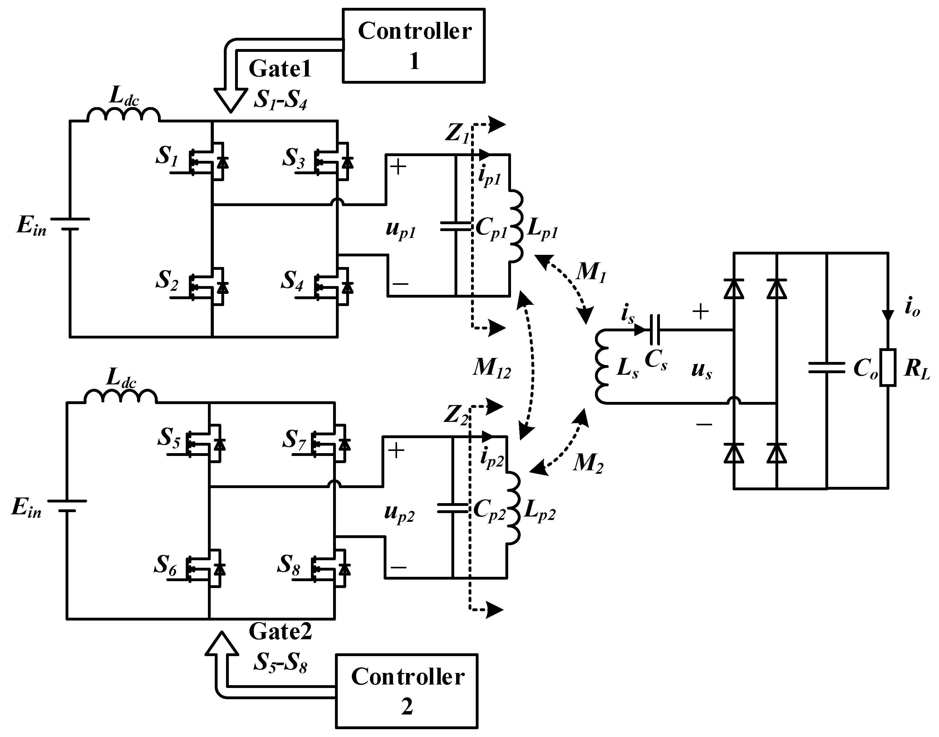
The equivalent circuit of the circuit model is shown in
Figure 2, where
Lp1,
Lp2 are primary coil and
Ls are secondary coil inductance, respectively.
Cp1,
Cp2, and
Cs are the resonant capacitance.
ip1,
ip2 are resonant currents in the coil.
up1 and
up2 are resonant voltage at the primary side.
Z1 and
Z2 are the reflection impedance.
Co is the capacitance of rectifier circuit, and
RL is the equivalent load resistance.
According to the KVL’s (Kirchhoff Laws) law, the phasor equation of voltage and current in the DEU-WPT system can be derived as
where
. In order to obtain balanced excitation, assume that
Lp =
Lp1 =
Lp2. The process variables are defined as follows
The primary current equation can be derived by
According to (1) and (3), the impedance of the primary coil branch can be deduced as
As can be seen in (3) and (4), the impedance of the primary coil branch changes with equivalent load variation when
M1,
M2, and
M12 changes under the condition of charging. When the value of
M1 and
M2 is closed, the order of magnitude of
is small, which is almost equal to 0. Equation (4) can be derived as
In other words, the coil resistance and reflection impedance will dominate the real part of
Z1 and
Z2, which depends on mutual inductance. Similarly, the imaginary part of
Z1 and
Z2 is decided by
M12 and
Lp. The resonant frequency of the secondary resonant tank can be designed as
The compensation capacitance of primary side of DEU-WPT can be obtained
3. Comparison Analysis between WPT and DEU-WPT System
It is necessary that a comparison analysis between a classical WPT system and a DEU-WPT system should be considered. To analyze the characteristics of the system more intuitively, assume that
M1 =
M2 =
M for simplicity, and the impedance of the primary coil branch can be expressed as
From (8), the real part of
and
are reflection impedance, which are twice than the reflecting impedance of traditional WPT system. When
,
and the parameters of dual excitation units are same (that is,
), the resonant current on the coil can be derived as
The output power can be deduced as
Considering the loss of resistance
and
, the loss of the primary resonant network for
and secondary loss of
is as follows
The expression for the efficiency can be obtained
where
is much greater than
; this formula can be simplified for
In order to analyze the output characteristics of DEU-WPT system,
Table 1 gives a comparison of PS (Primary Parallel Secondary Series) DEU-WPT systems as well as traditional PS-type WPT systems in the case of the same parameter matching. Where the
is the mutual inductance of WPT,
is the mutual inductance of DEU-WPT and the
is the cross-coupling inductance of DEU-WPT.
is the reflection impedance of the system.
and
are the impedance angle of the primary resonant network, which equals to the imaginary part divided by the real part of an impedance.
Table 1 shows that the reflection impedance
Zrs of DEU-WPT is two times that of classical WPT. Furthermore, the efficiency
η of the DEU-WPT system has obviously been improved because the ratio of numerator to the denominator of
η increases. In practice, the resonant network cannot be matched ideally, and the coupling coefficient of cross-mutual inductance is generally less than 0.05, so
because of reflection impedance
Zrs (real part of impedance) of DEU-WPT is much greater while the imaginary part of DEU-WPT (
) is almost equal to the imaginary part of WPT (
); that is to say, the
of DEU-WPT is reduced. Similarly, compared with classical WPT system, the
of DEU-WPT is reduced to a certain extent due to the increase of reflected impedance and the existence of cross-mutual inductance.
However, to verify the PS topology, the DEU-WPT system has improved the output power compared with the traditional PS topology WPT, only needing to guarantee
where
represents the output power of DEU-WPT and
represents the output power of WPT. To prove (14), assume that
and bring in the expressions of resonant current in
Table 1, as follows
From (16), when , the inequality is equal. However, the loose coupling coefficient k is generally equal to or less than 0.3, so obviously. It can be concluded that, in theory, the output power of the PS topology DEU-WPT can increase the output power by four times compared with the PS topology WPT when Lp >> M12.
Generally, it is justified that the DEU-WPT system reduced the stress of voltage and current in resonant tank compared to a classical WPT system, and cross-coupling
M1 and
M2 will have a direct influence on impedance matching. Additionally, the cross-coupling
M12 between dual primary units will influence the power gain, which can be seen in Equation (16). The optimum output characteristic of system will be analyzed specifically in
Section 5 when the mutual inductance is asymmetric.
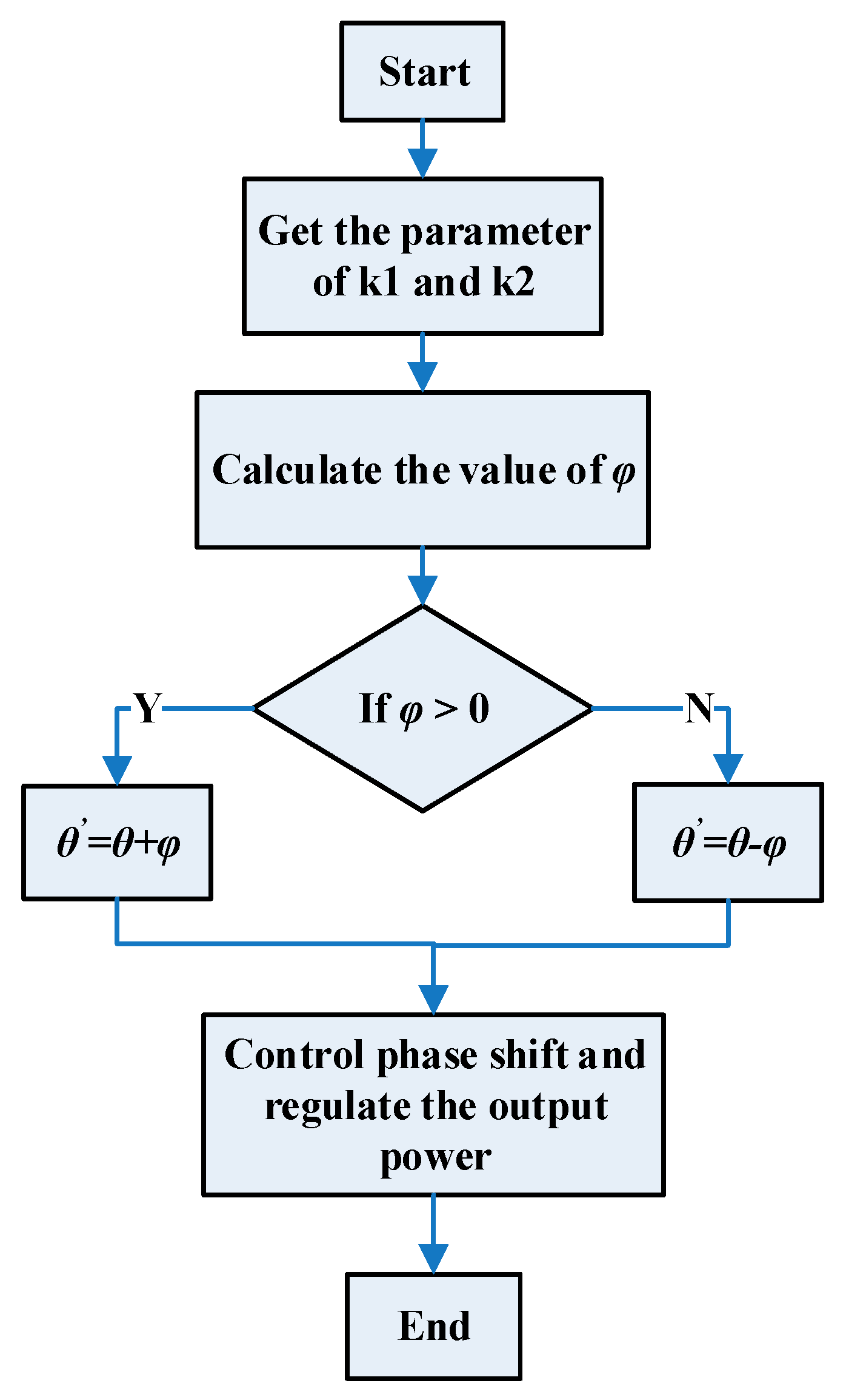
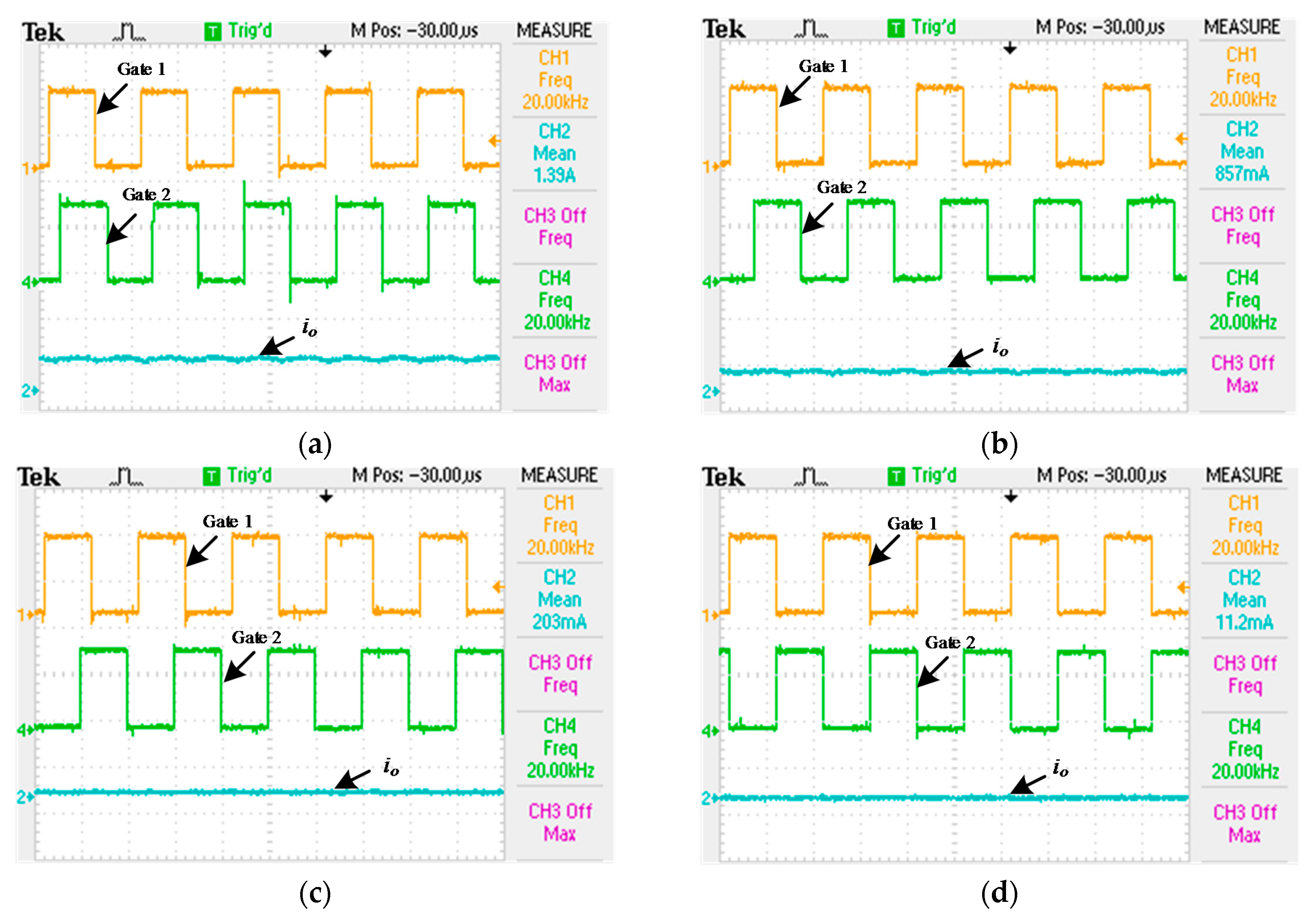
4. Control Method of Output Power
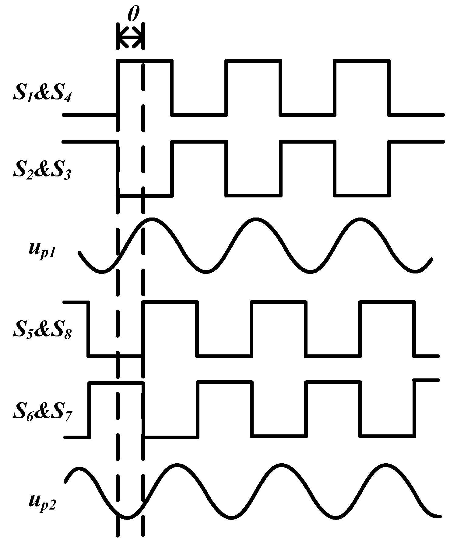
For the DEU-WPT system, the phase difference
θ between resonant current
and
will directly influence the magnetic field intensity. This paper proposed an output power regulation method to control
and
so that phase difference
θ between
and
could be regulated.
Figure 3 gives the phase-shifted waveform. The resonant voltage phasor is controlled by phase-shift of the driving signal, as shown in
Figure 3;
S1–
S4 is the driving signal in inverter 1, and
S5–
S8 is the driving signal in inverter 2.
According to (1), the
and
be expressed as
where
, and the RMS (Root Mean Square) of
on the secondary side can be derived as
Because
and
, set the phase offset
between
and
as
Output power
can be obtained
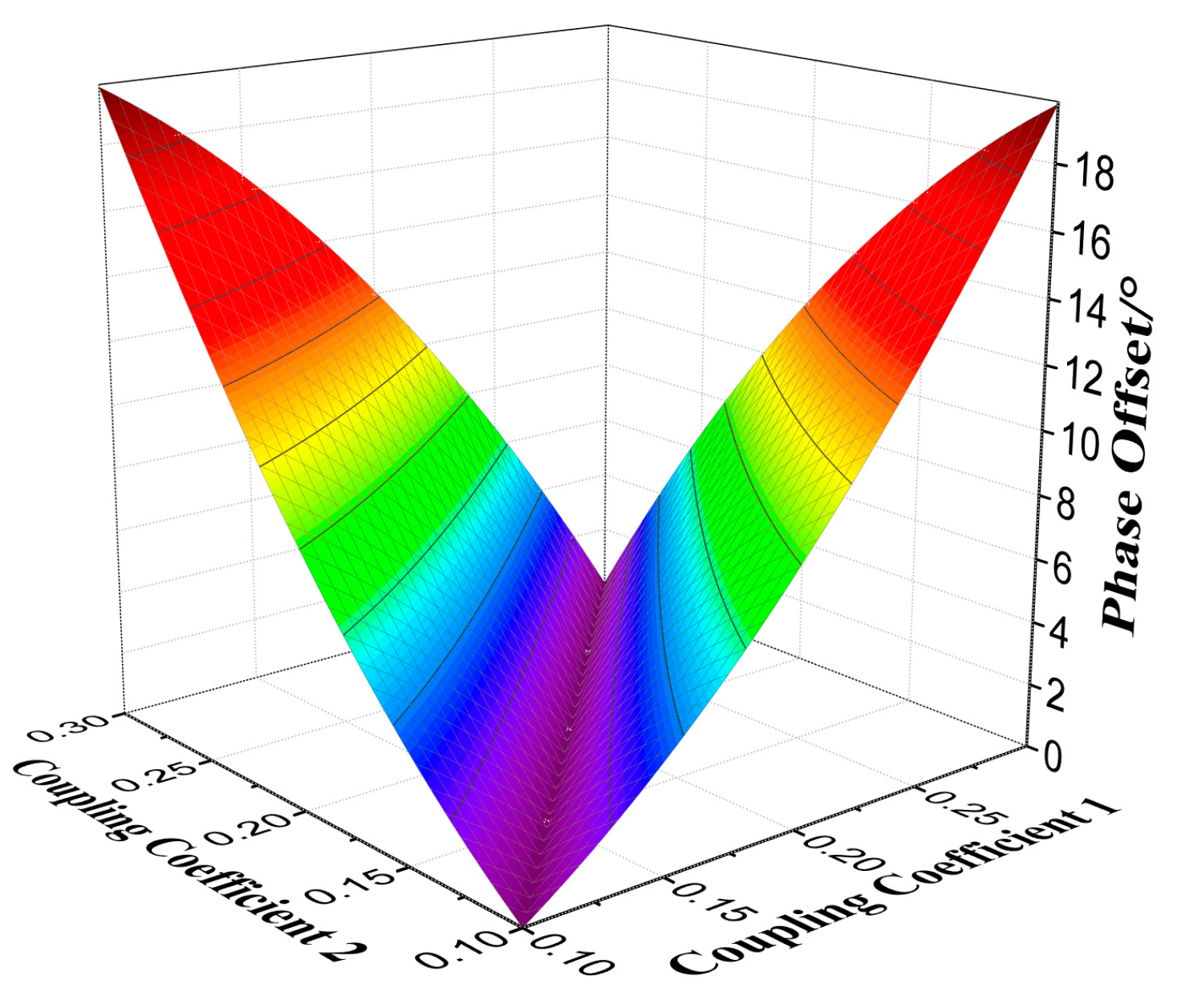
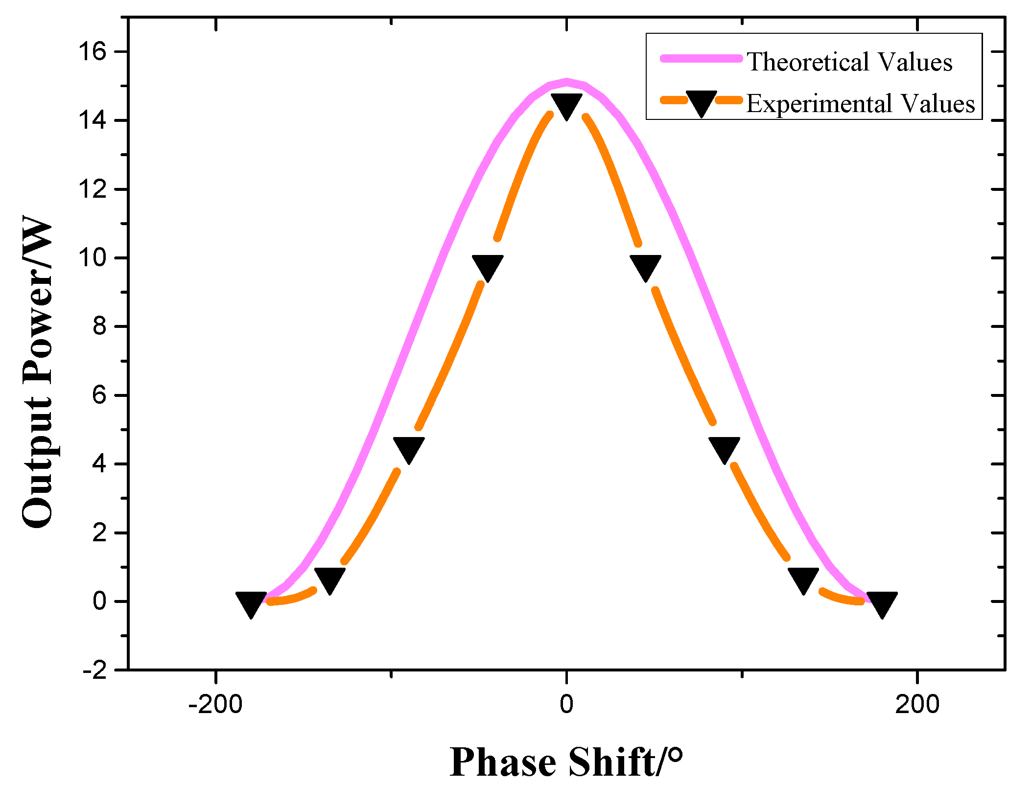
According to (19), phase offset
is dependent on different coupling coefficients.
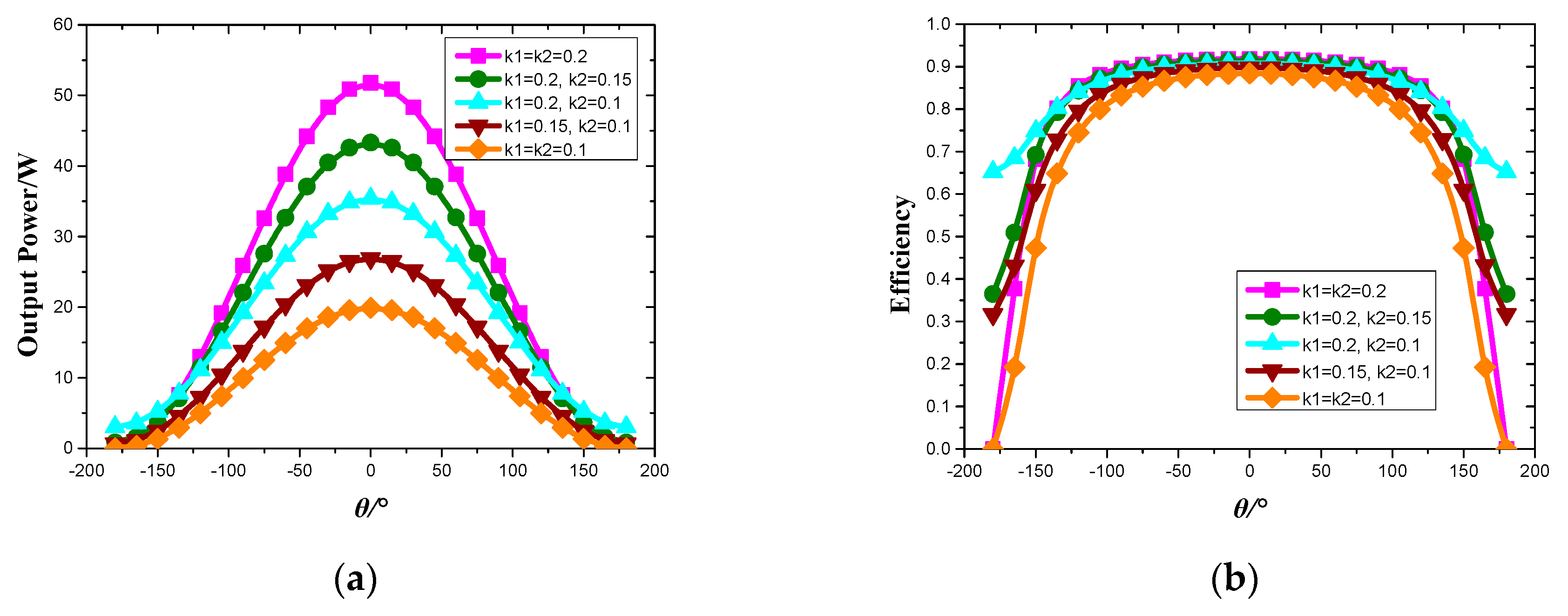
Figure 4 shows the phase offset variation with respect to coupling coefficients k1 and k2, where k1 and k2 are from 0.1 to 0.3.
In
Figure 4, the phase offset
changes from 0 degrees to 18 degrees. From papers, mutual inductance could be calculated. Then, the phase offset could be determined by Formula (10). In order to eliminate the phase offset
and realize the output power regulation, the flow chart of phase-shift is in
Figure 5.
It should be noted that prior knowledge of k1 and k2 should be obtained before phase-shift regulation. There are a few online identification methods [
18,
19] which can be utilized in the practice.
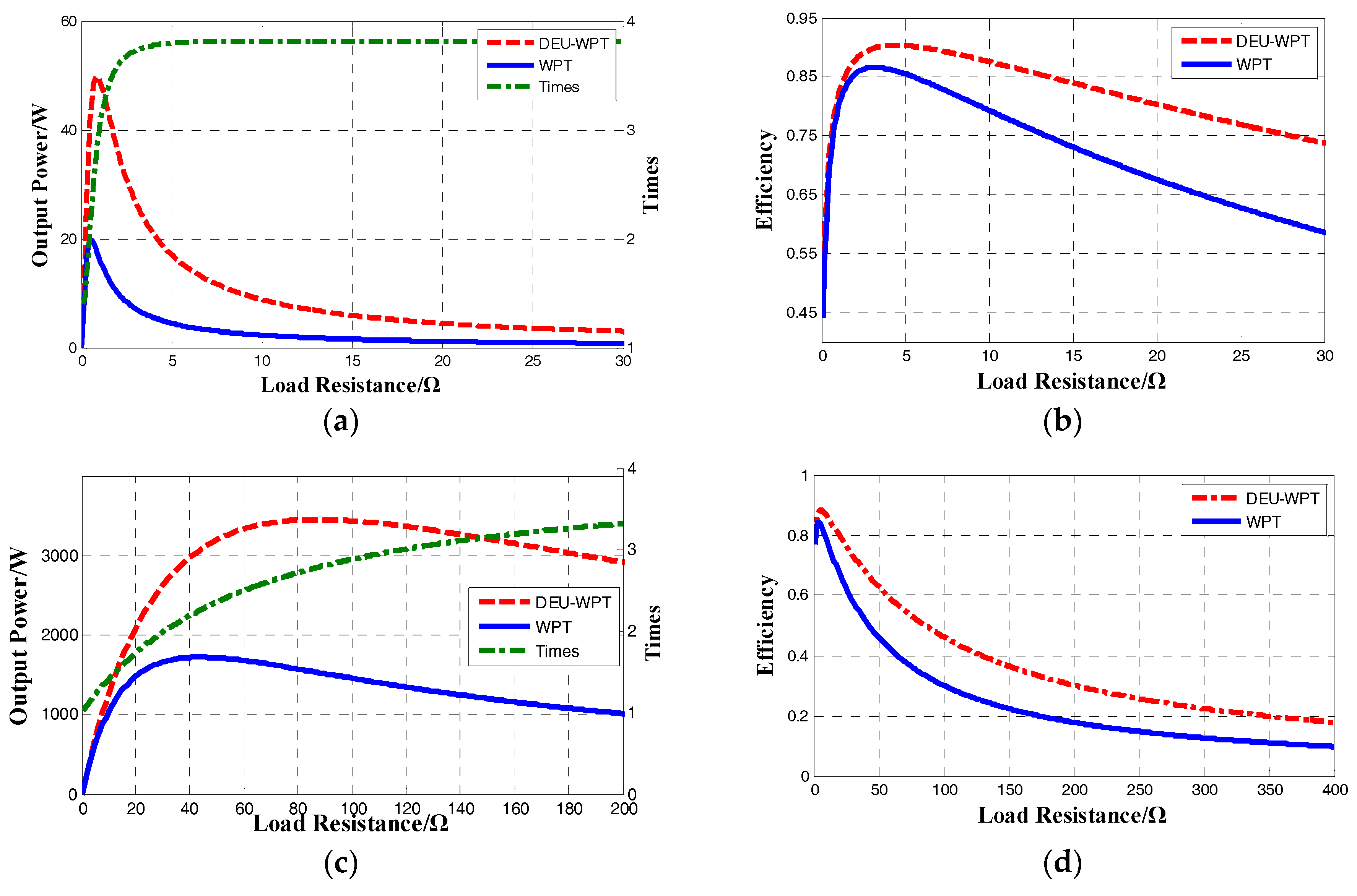
7. Conclusions
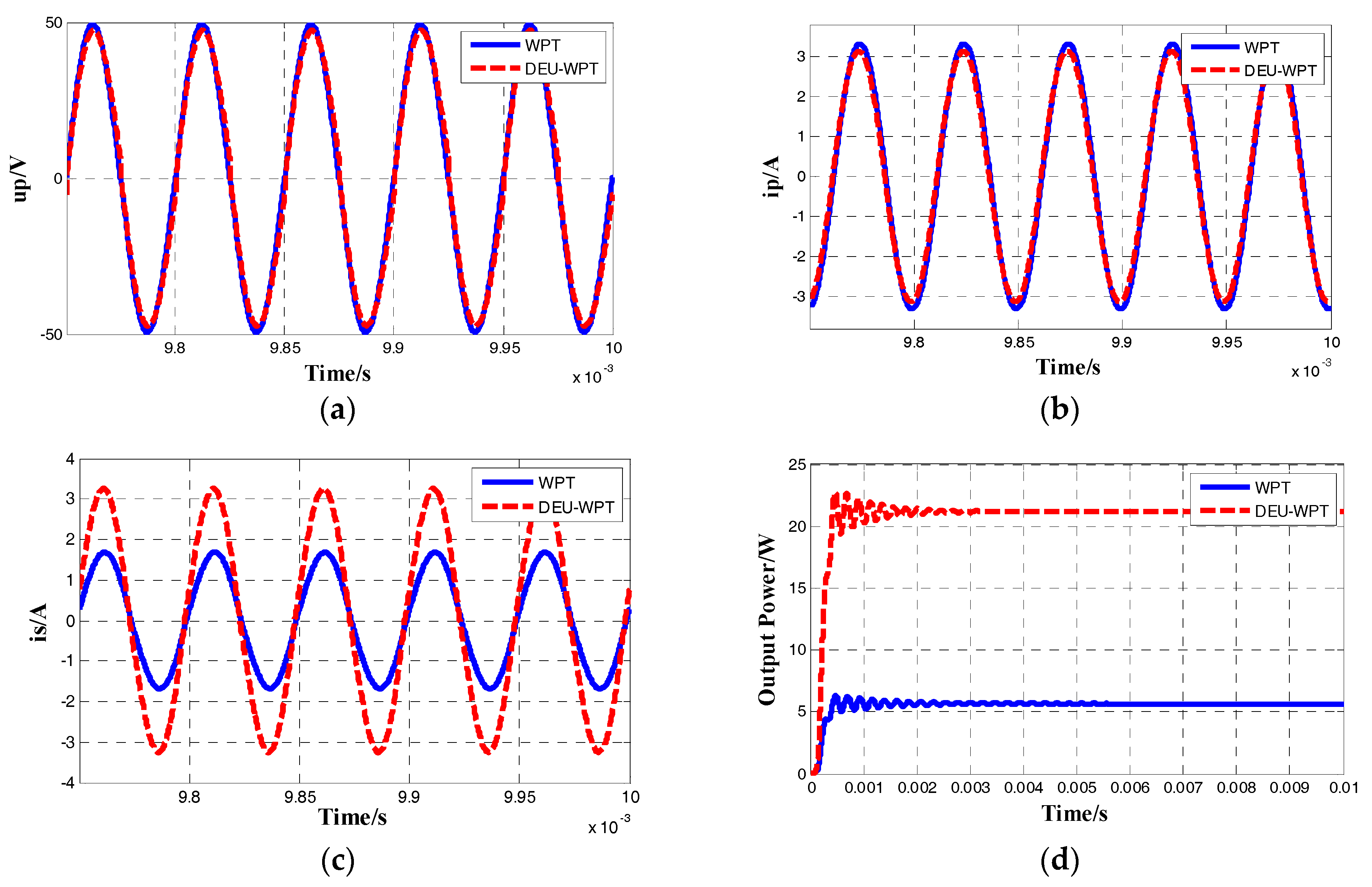
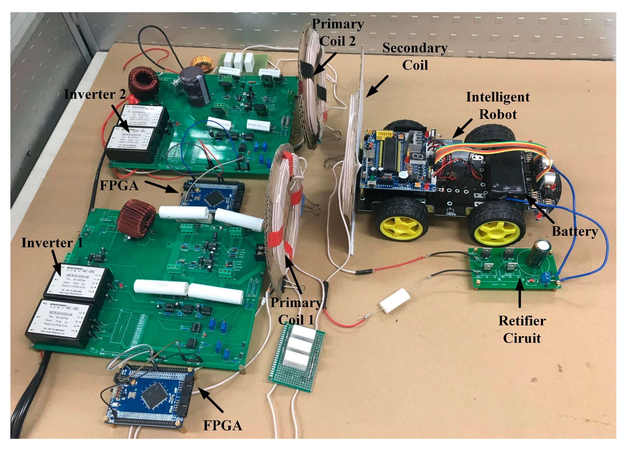
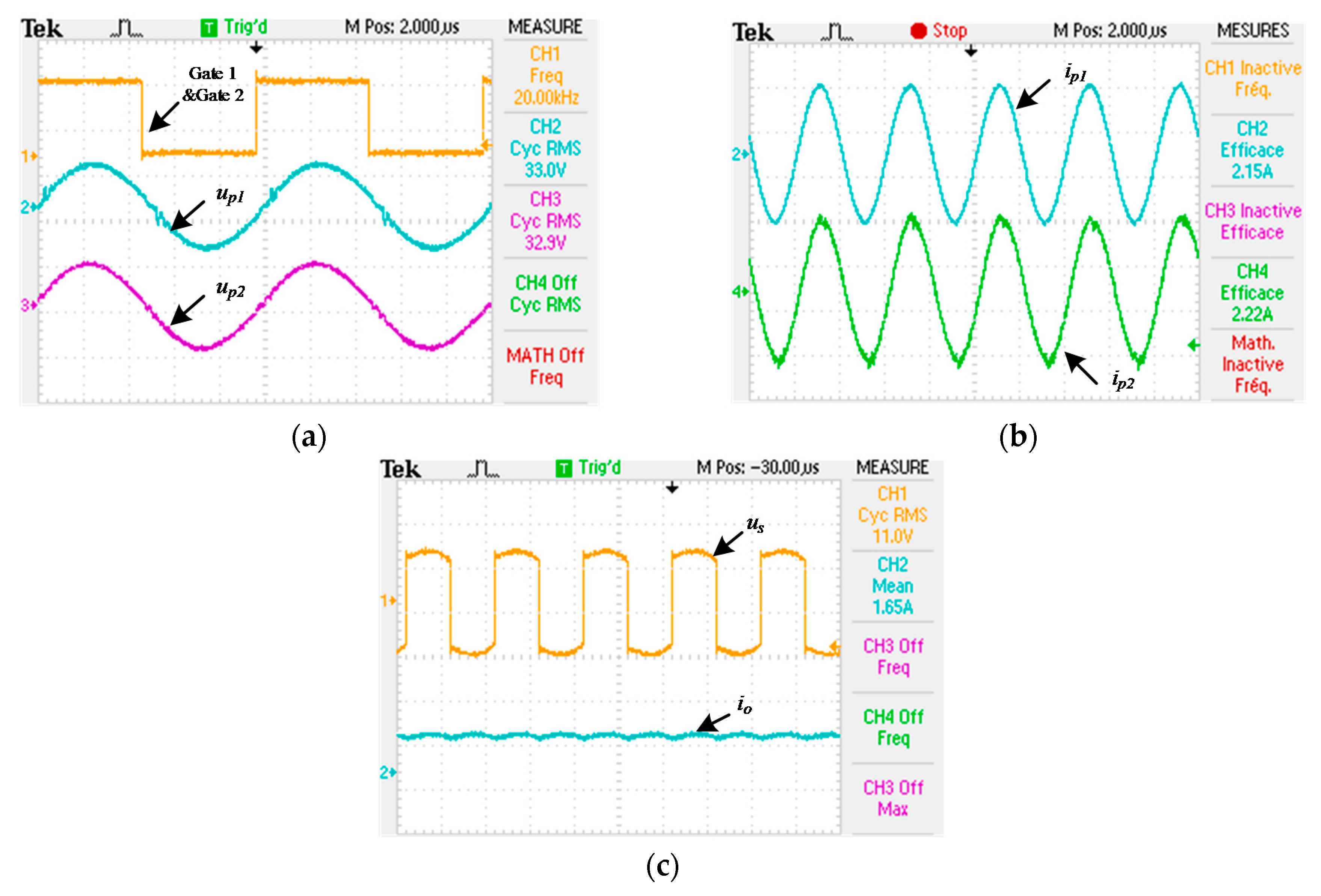
In this paper, a DEU-WPT system for charging intelligent robots is built, and a method of output power modulation is proposed. Compared with traditional the WPT system, the DEU-WPT system has the following benefits: (1) Compared to the traditional system, output characteristics of the PS-type DEU-WPT have been improved significantly. Not only can output power of DEU-WPT increase by 3.3 times, but the efficiency of DEU-WPT has also increased by 9%. The reliability of the system has enhanced. (2) The power modulation is realized by the current phase control of the primary coil, which reduces the harmonics and improves the flexibility of the system. (3) Reducing the stress of voltage and current of the primary resonant network enhances the security of the system. (4) The PS-type DEU-WPT system is more stable than PS-type WPT for intelligent robots in both dynamic charging and static charging. In summary, the DEU-WPT system has advantages compared with the traditional system, providing a new method to improve the output characteristics of robot charging based on wireless power transfer, and provides a new way to solve the system security problem.
By comparing with the traditional WPT topology, it is found that the DEU-WPT system can significantly increase output power and efficiency while reducing the stress of voltage and current in the resonant network. At the same time, the DEU-WPT is more robust than general WPT system under the condition of parameter variation.


