1. Introduction
Solar desiccant cooling technology has been widely investigated and applied all over the world during the past years. It has been found to be environmentally friendly, and in some circumstances economically beneficial, as it is able to improve indoor air quality while at the same time reducing energy consumption [
1,
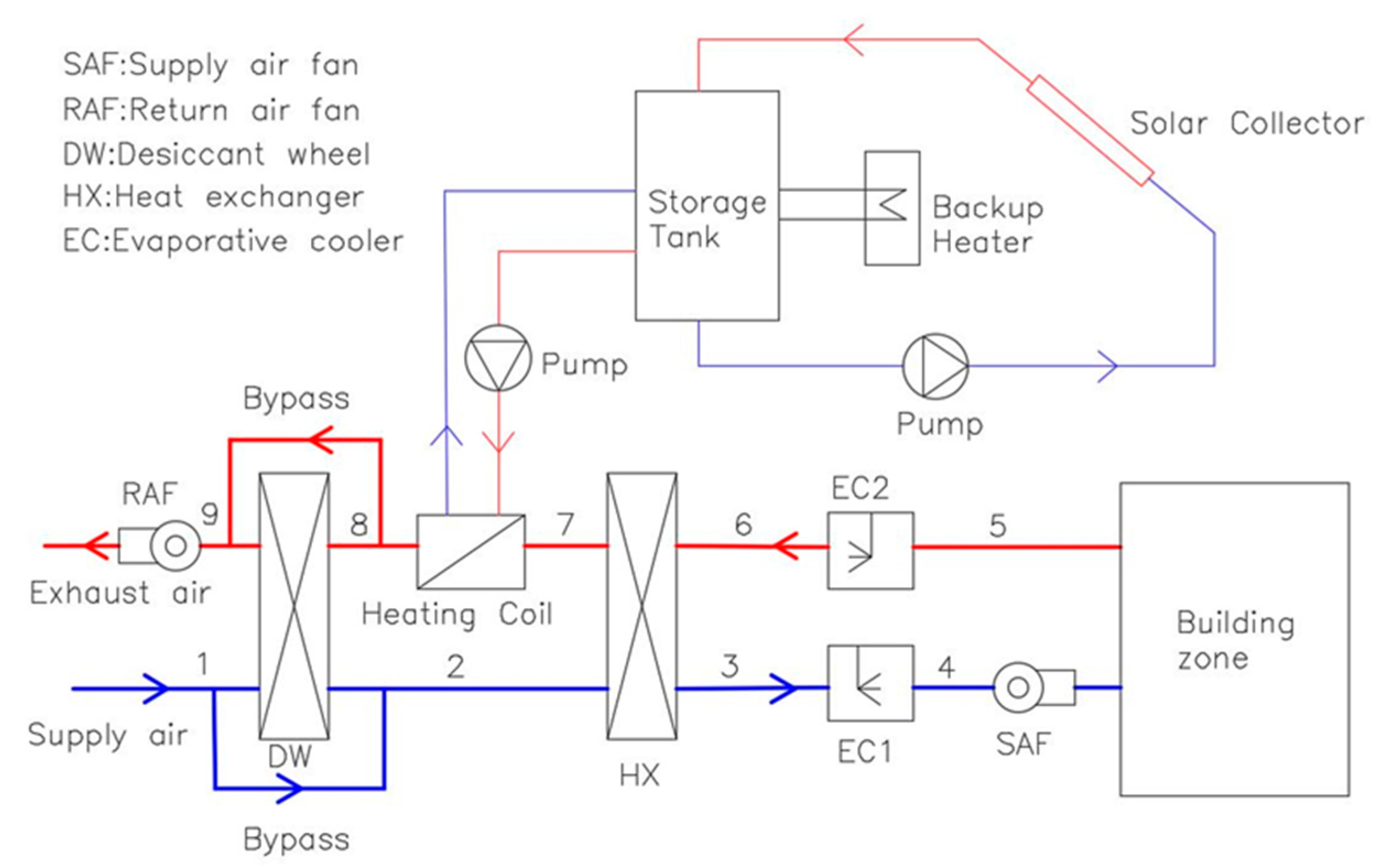
2]. The basic solar desiccant cooling system generally combines the desiccant process with evaporative cooling. A typical solar desiccant evaporative cooling (SDEC) system is mainly comprised of: (1) a solar subsystem which consists of solar collectors, a storage tank and a backup heater; (2) a desiccant subsystem which includes a desiccant wheel, desiccant materials (usually silica gel), a regeneration heating coil, and a sensible air-to-air heat exchanger; and (3) evaporative coolers. The schematic diagram of a typical SDEC system is illustrated in
Figure 1 [
3].
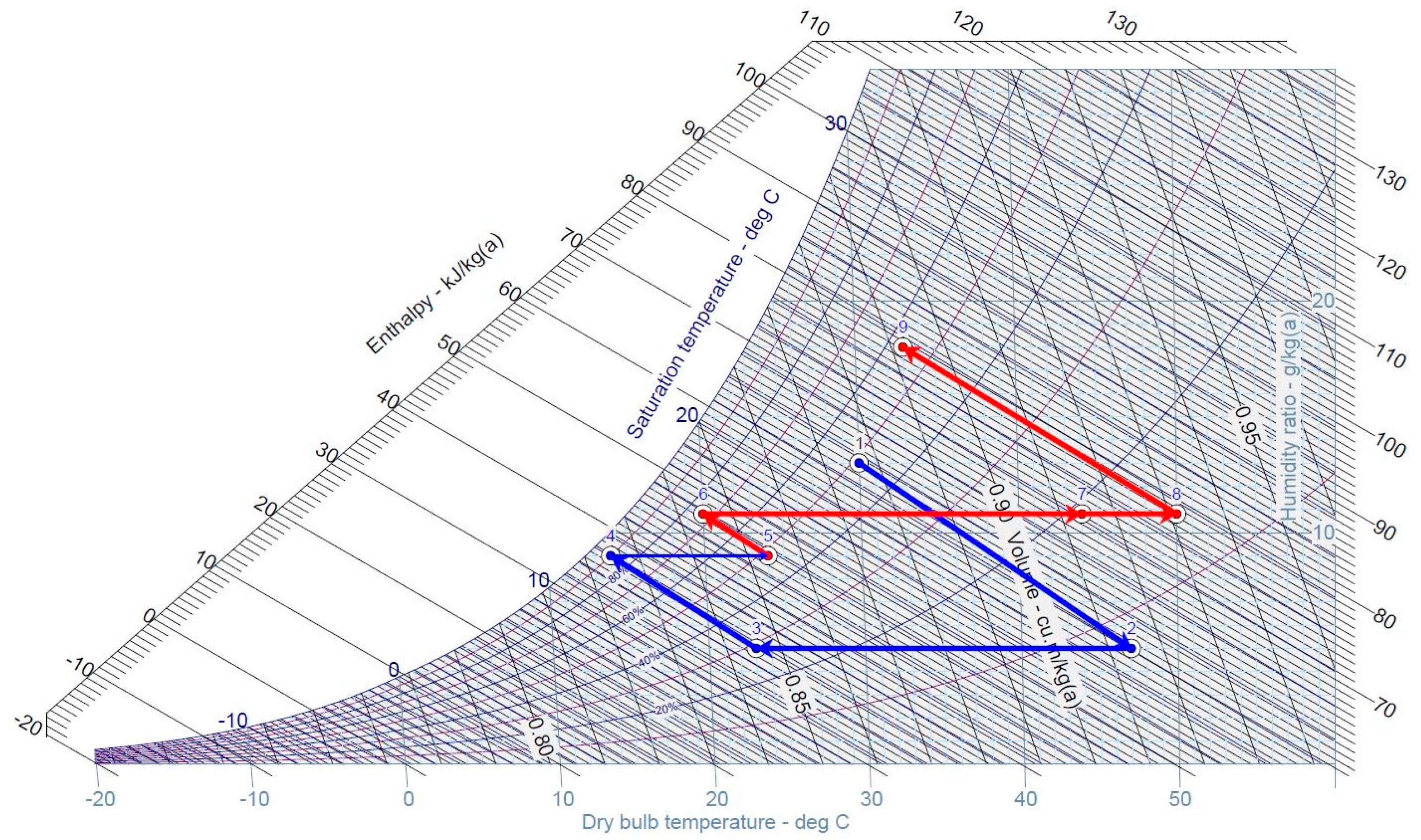
The SDEC system treats the sensible load and latent load of the supply air separately. The working principle of the solar desiccant cooling system is that the desiccant material in the desiccant wheel first dries and heats the outside air (1–2), then the dehumidified process air is cooled to near ambient temperature through a sensible air-to-air rotary heat exchanger (2–3). The process air is further cooled by the evaporative cooler (3–4) and is eventually sent to the conditioned space. In the regeneration air stream, the return air is cooled by a second evaporative cooler (5–6) in order to increase the heat exchanger’s efficiency. It is then heated to the regeneration temperature by the regeneration air heater (7–8). The continuous air dehumidification process saturates the desiccant material which must be regenerated in order to continue to perform its function. Thus, solar thermal energy is supplied to the regeneration heating coil for regeneration purposes. A backup heater is usually included whenever solar energy is insufficient.
Currently many research articles have examined the performance of the solar desiccant cooling system in the world. Baniyounes et al. [
1] conducted the study of a solar desiccant cooling for an institutional building in Australian subtropical climate Rockhampton using TRNSYS 16 (software developed at the University of Wisconsin, Madison, SD, USA). They demonstrated that the system would achieve an annual coefficient of performance (
COP) of 0.7, a 22% solar fraction (
SF), 4.4 tonnes of greenhouse gas (GHG) emissions reduction, and 22 years payback by installing 10 m
2 solar collectors and 0.4 m
3 storage tank. Angrisani et al. [
2] assessed the energy, environmental, and economic performances of a solar desiccant-based air handling unit (AHU) with three types of collectors: solar air collector, flat plate collector, and evacuated tube collector. They found that energy and environmental benefits increased with the solar collector surface, but the thermo-economic performance was not in proportion to the solar collector surface. The best solution for achieving the economic feasibility of the solar desiccant cooling system was the installation of 16 m
2 evacuated tube collectors, which allowed 50.2% primary energy savings and 49.8% CO
2 emissions reduction compared to the referenced conventional system, with about 20 years payback period. Rafique et al. [
4] conducted a theoretical analysis of desiccant-based evaporative cooling systems for five cities in Saudi Arabia. They found that the system thermal
COP ranged from 0.275 to 0.476 based on different locations. They also concluded that an increase of 15% in evaporative cooler effectiveness resulted in about 15 to 25% increase in the system thermal
COP. Furthermore, a decrease in system
COP would be caused by an increase in regeneration temperature and process/regeneration air flow ratio. In addition, the desiccant wheel dehumidifying efficiency increased with the increase of the ambient air humidity ratio. Angrisani et al. [
5] again investigated three alternative configurations of an innovative solar-assisted hybrid desiccant-based AHU through TRNSYS 16 simulation: (1) heat recovery from the chiller heat rejection for pre-heating the regeneration air; (2) pre-heating of regeneration air with the warmer regeneration air exiting the desiccant wheel; and (3) pre-cooling of the process air before entering the desiccant wheel. By considering different collector types, surface areas and tilt angles, they indicated that the desiccant-based AHU with evacuated tube collectors could achieve 15 to 24% primary energy conservation and 14 to 22% CO
2 emissions reduction compared to conventional cooling systems. If the optimal configurations in terms of the solar thermal energy utilisation, surface areas, and tilt angles were adopted, the evacuated tube collectors could ensure 73% primary energy savings and 71% avoided equivalent CO
2 emissions with only 6 years payback period. Li et al. [
6] conducted a case study of a two-stage solar desiccant air conditioning system using evacuated tube air collectors in China. They found that the average thermal
COP could be 0.97 in cooling and 0.45 in heating. Ge et al. [
7] compared the performance of a two-stage solar rotary desiccant cooling system with a conventional vapour compression system under Berlin and Shanghai climates. They indicated that the SDEC system was able to meet the cooling demand and produce comfortable supply air in both cities with less energy consumption, and the payback period was 4.7 years for Berlin and 7.2 years for Shanghai, respectively.
There are also a number of recent research studies that have been investigated to evaluate the impacts of various system components design parameters on the solar desiccant cooling system performance in different climates. Goldsworthy and White [
8] conducted the numerical optimisation of a solar desiccant cooling system for a certain climatic zone in Australia. They found that for 70 °C regeneration temperature, a supply/regeneration flow ratio of 0.67 and an indirect evaporative cooler secondary/primary flow ratio of 0.3 gave the best system performance with the electric
COP above 20 for this particular location. It should be noted that the electric
COP of the SDEC system reported in the study is much larger than the thermal
COP (ranges from 0.275 to 0.97) discussed above. This is because of the different definitions and calculation formulas between the thermal
COP and electric
COP. The thermal
COP is defined as the ratio between the system cooling effect to the external heat delivered to the regeneration air heater; while the electric
COP is calculated as the system cooling effect to the total system electricity consumption including fans, pumps, and auxiliary heater, etc. [
9]. The definition and formula expression of the electric
COP is quite similar to the energy efficient ratio (EER), which also takes into consideration of the consumption of electrical-consumed auxiliary devices. White et al. [
10] assessed the performance of a solar desiccant cooling system without thermal backup for office spaces located in Melbourne, Sydney, and Darwin. They concluded that increasing the indirect evaporative effectiveness, supply air flow rate, and solar collector areas would apparently result in reduced frequency of high indoor temperature events in Melbourne and Sydney, but this impact was not evident in Darwin due to high outdoor air temperature and humidity ratio in Darwin. Parmar and Hindoliya [
11] conducted a comparable study of a SDEC system for various Indian climates. They concluded that a regeneration/process air ratio (R/P ratio) of 0.55 led to the maximum thermal
COP of 4.98 in warm and humid climates such as Mumbai with less regeneration power and that the increase of the R/P ratio would result in decreased system
COP and increased regeneration heat requirement. It should also be noticed that according to [
9], the thermal
COP of a solar desiccant cooling system strongly depends on the conditions of ambient air, supply air, and return air, and the value usually ranges from 0.5 to 1.0. In this study however, the high thermal
COP value of 4.98 is because that the system thermal
COP is highly sensitive to the R/P ratio. In addition, the warm and humid outside air conditions in Mumbai make the solar desiccant cooling system more feasible and advantageous. Zahra et al. [
12] presented an optimisation study of the required solar air collector areas for a solar desiccant cooling system in Iran by considering the desiccant wheel parameters and operating conditions. They found that the solar air collector surface would be decreased by increasing the collector inlet air dry-bulb temperature, inlet air humidity ratio, and solar irradiance; and it would be increased by increasing the regeneration air temperature. Panaras et al. [
13] investigated the influential design parameters for the solar desiccant cooling system performance and they indicated that the air flow rate, regeneration temperature, operation cycle, and outdoor conditions have significant impacts on the solar desiccant cooling system performance. Rafique et al. [
14] conducted a parametric analysis of a rotary liquid desiccant cooling system under various operating and climatic conditions. The parameters considered included evaporative cooler effectiveness, outside air temperature and humidity ratio, ratio of regeneration air to process air mass flow rate, and regeneration temperature. It was found that the increase of the evaporative cooler effectiveness would significantly improve the system performance. In addition, decreasing the regeneration/process air mass flow rate ratio and regeneration temperature was beneficial for the performance of the system. Apart from the solar desiccant cooling system parameters analysis, Giulio et al. [
15] conducted a dynamic multi-level simulation using Matlab/Simulink for a solar adsorption cooling system to identify the correlations among different input variables and the climatic data. By performing the Fourier analysis, they concluded that the most important parameters influencing the system
COP, in order of importance, were ambient air temperature, condensation power of the adsorption chiller, chiller cooling effect, and heating power used by the chiller. They also found that the thermal power delivered to the hot storage unit was strongly correlated with, in order of priority, the adsorbent material temperature, condensation temperature, ambient temperature, and the heating power used by the chiller.
From the literature review, it appears that previous research has indicated some implications of the system components design parameters on the system performance, such as maximising the system COP, minimising the solar collector areas, and reducing the frequency of high indoor temperature events. However, little research has been conducted about the impacts of different system components design parameters on the energy performance of the solar desiccant cooling system. In addition, there is little research about the parametric analysis of the SDEC system from the whole system performance point of view. There is also little research studies to evaluate the impacts of solar collector areas, storage tank volumes, backup heater capacities, and outdoor air humidity ratio control on the SDEC system performance in subtropical climate in Australia. Therefore, the purpose of this paper is to identify the impacts of the system components design parameters on the SDEC system technical and energy performances in Australia, in terms of solar collector area, storage tank volume, and backup heater capacity. In addition, an energy management system (EMS) control on the outdoor air humidity ratio set-point which triggers the operation of the desiccant wheel has also been evaluated. This study aims at establishing fundamental understanding of the influential design parameters that impact the SDEC system performance under Australian climate and providing implications for the whole system optimisation.
4. Conclusions
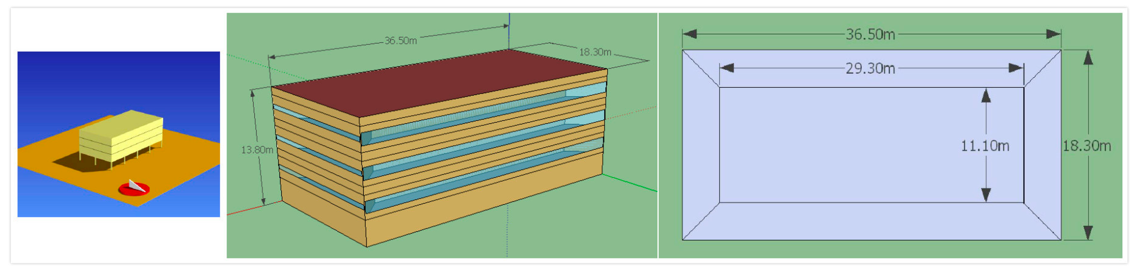
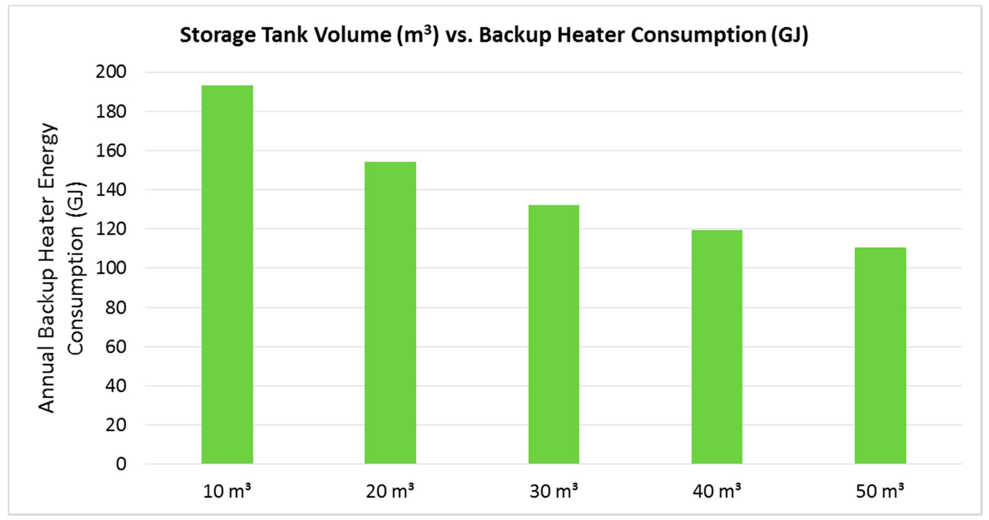
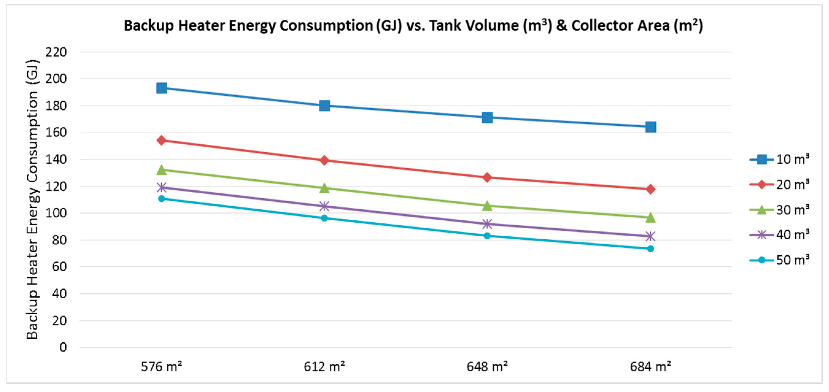
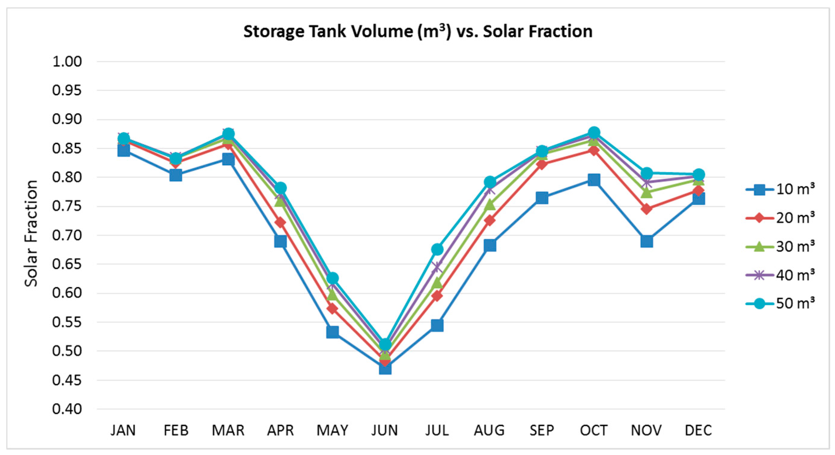
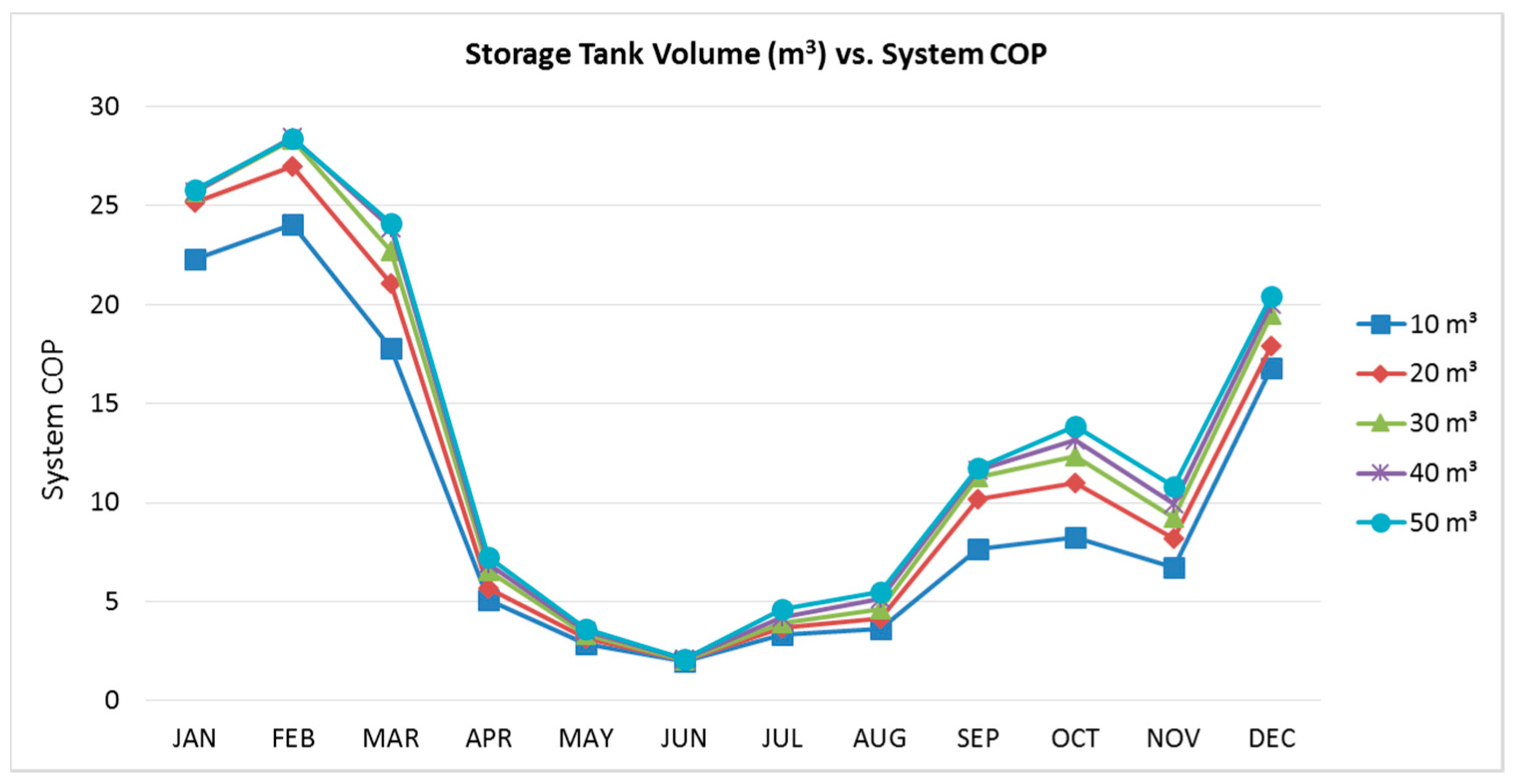
This paper has evaluated the factors that influence the SDEC system performance for a typical office building in Brisbane, Australia, in terms of the storage tank volume, solar collector area, backup heater capacity, and outdoor air humidity control set-point. The sensitivity analysis results have indicated that either increasing the storage tank volume or increasing solar collector area could result in improved system SF and system COP, while at the same time reduce backup heater energy consumption. When increasing the storage tank volume from 10 to 50 m3, the annual average system SF was increased by 11.4% from 0.7 to 0.78, and the annual average system electric COP was increased by 32% from 10.0 to 13.2. Meanwhile, the annual backup heater energy consumption was reduced by 43% from about 193 to 110 GJ.
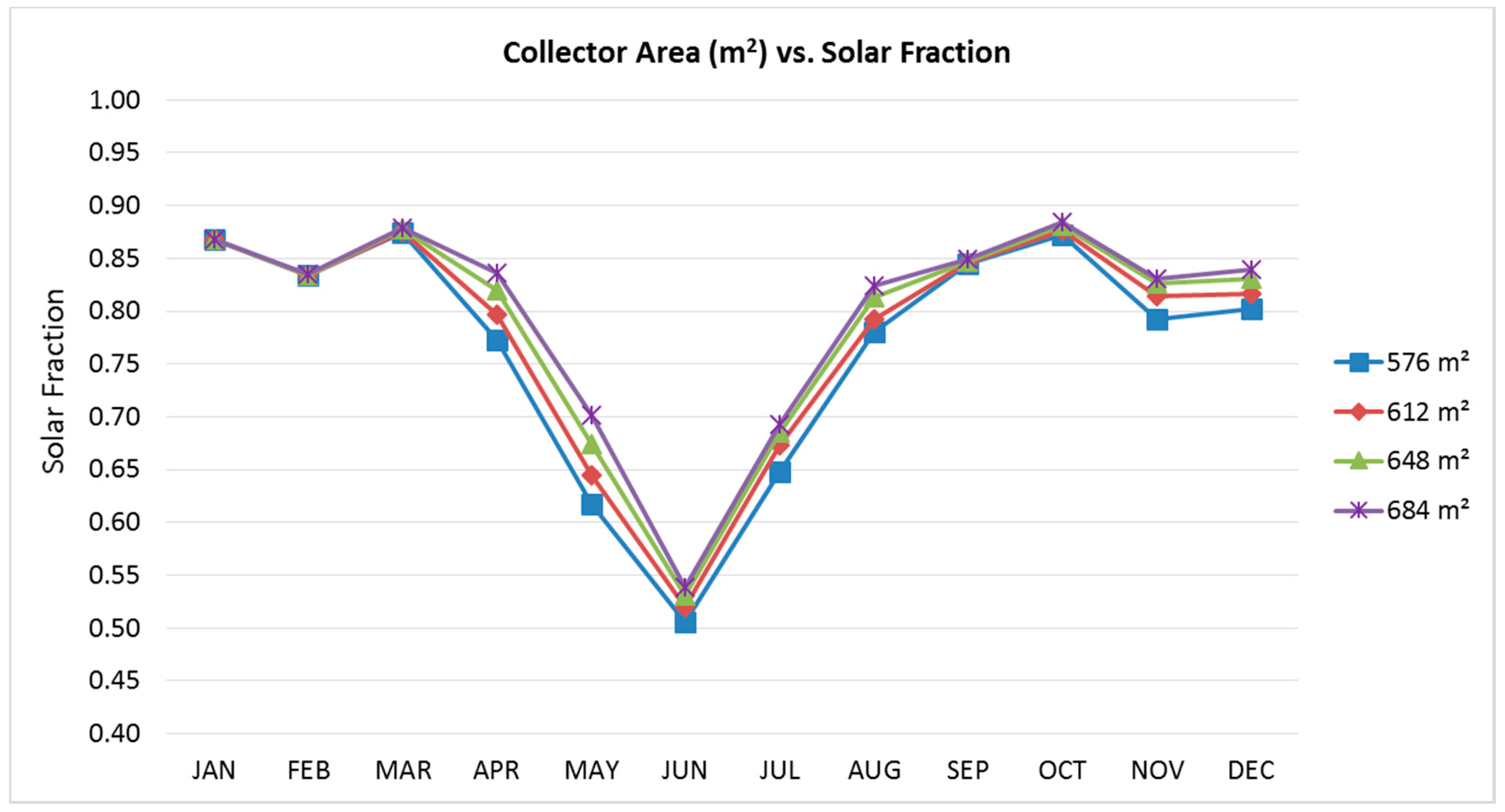
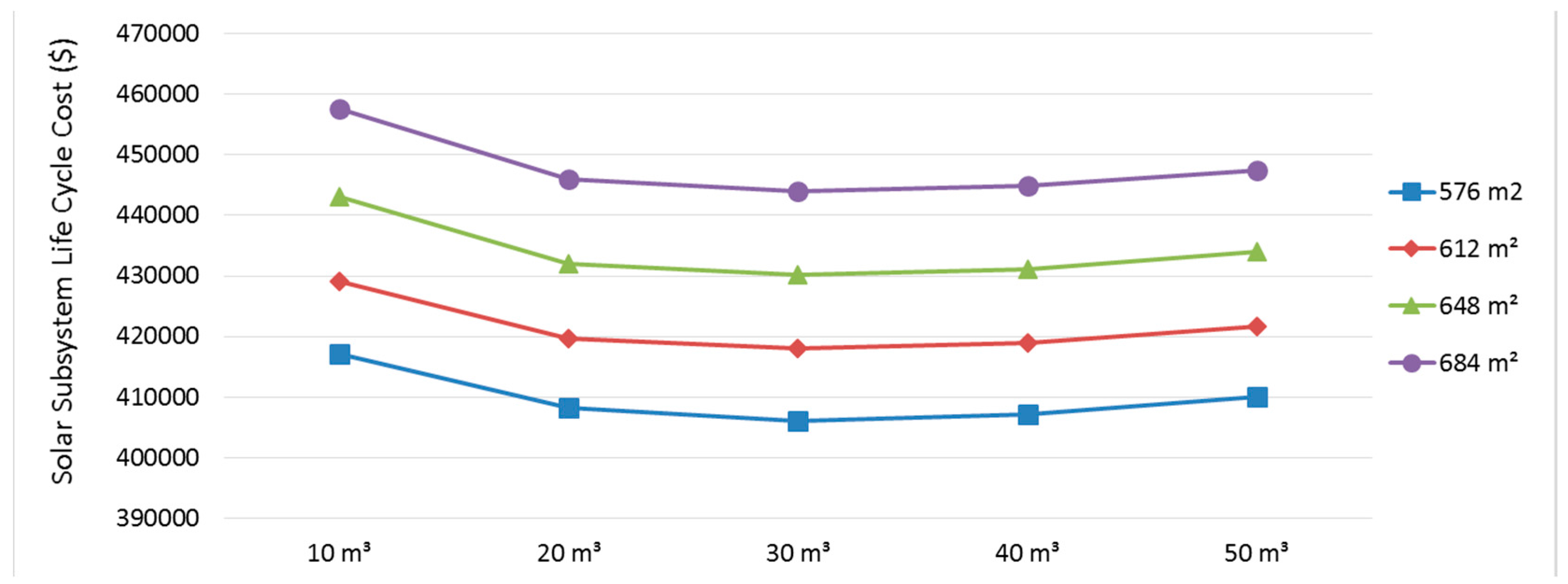
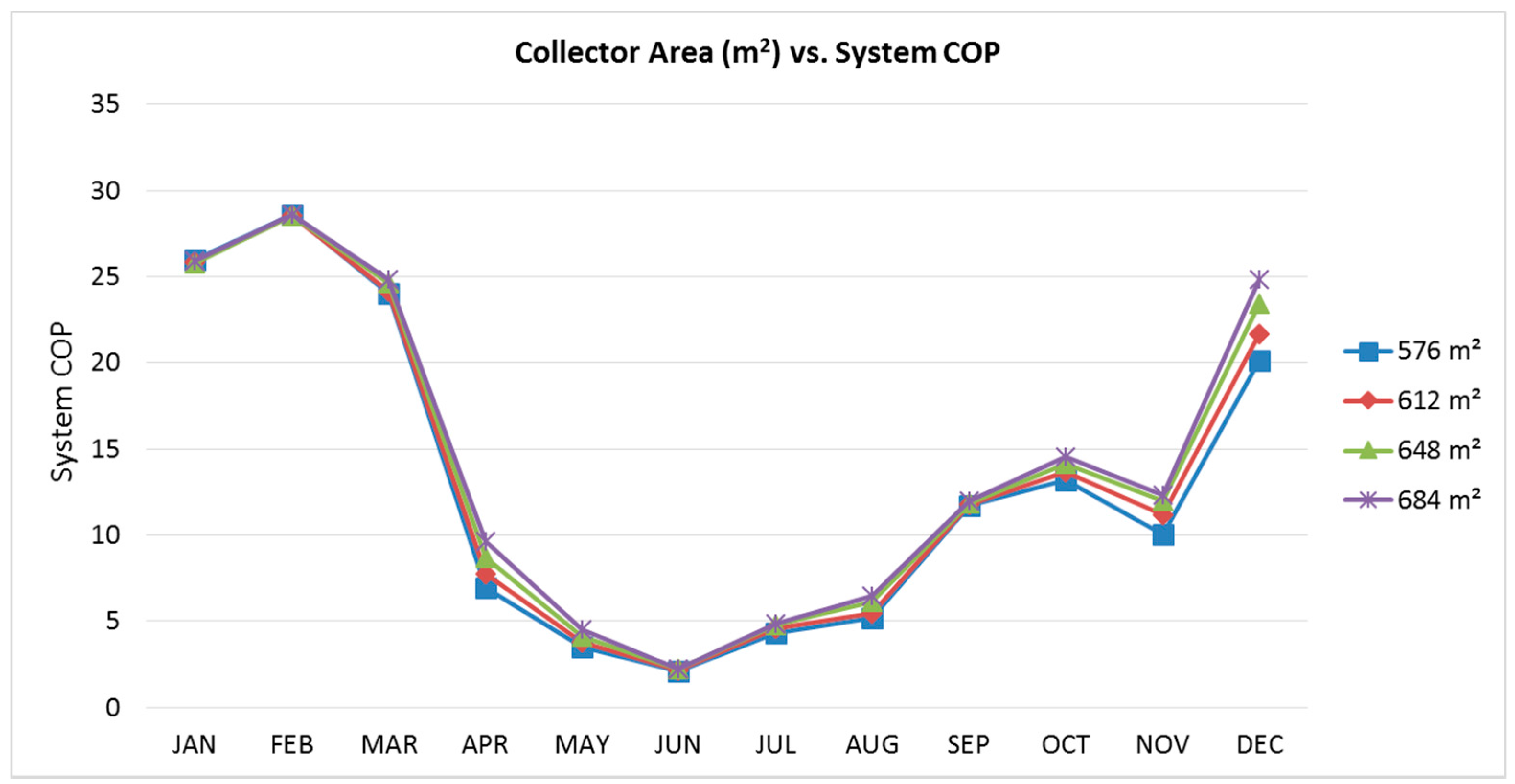
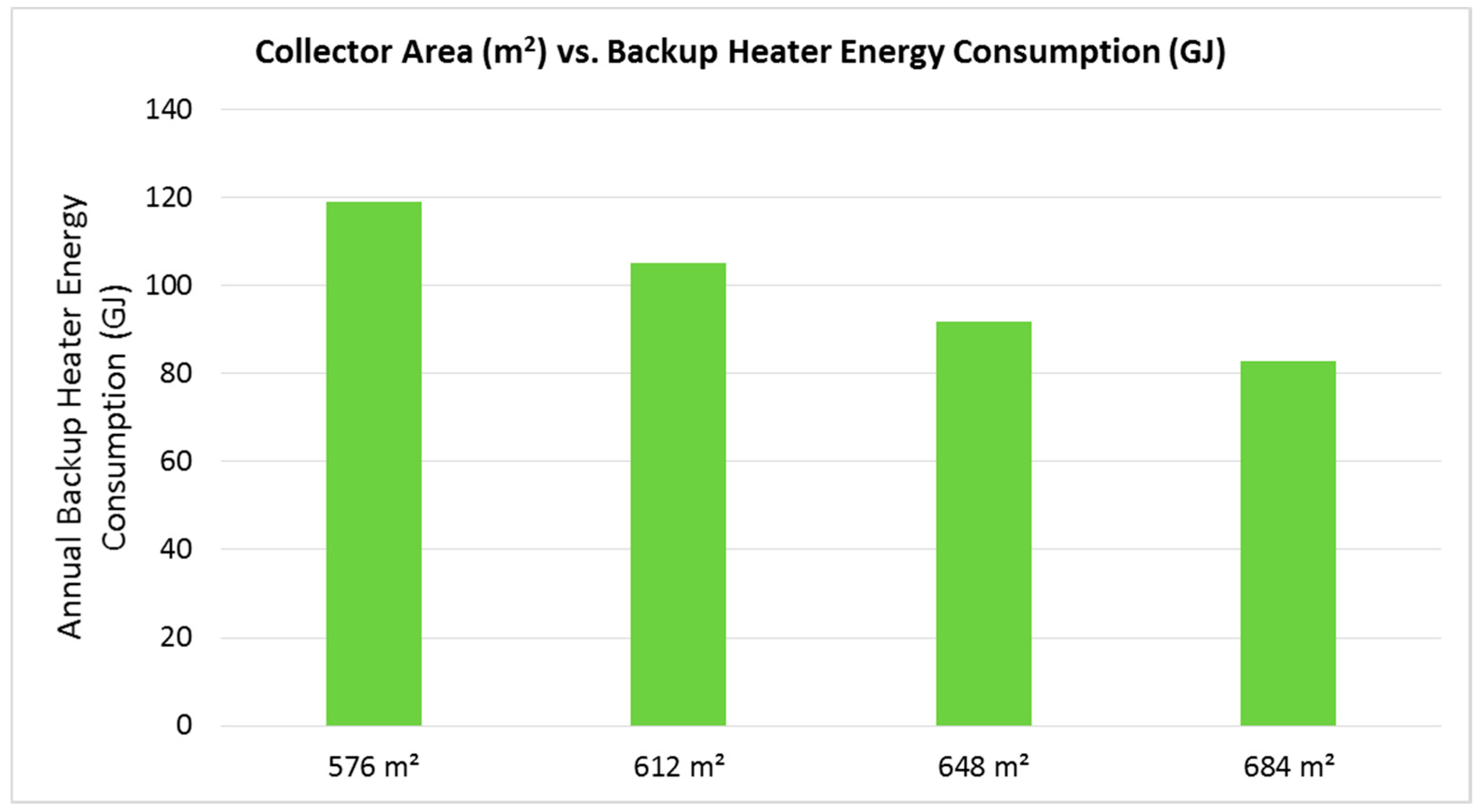
On the other hand, increasing the installed solar thermal collector area from 576 to 684 m2 resulted in 3.9% increase in the annual average system SF and 23% increase in the annual average system electric COP, along with about 30.4% annual backup heater energy savings. These implied that the storage tank volume was more sensitive to the SDEC system energy performance than the solar collector area. In addition, from the economic point of view, the 30 m3/576 m2 storage tank volume to solar collector area ratio has the lowest solar subsystem LCC of $405,954, which was the optimized configuration relating to storage tank volume and solar collector area.
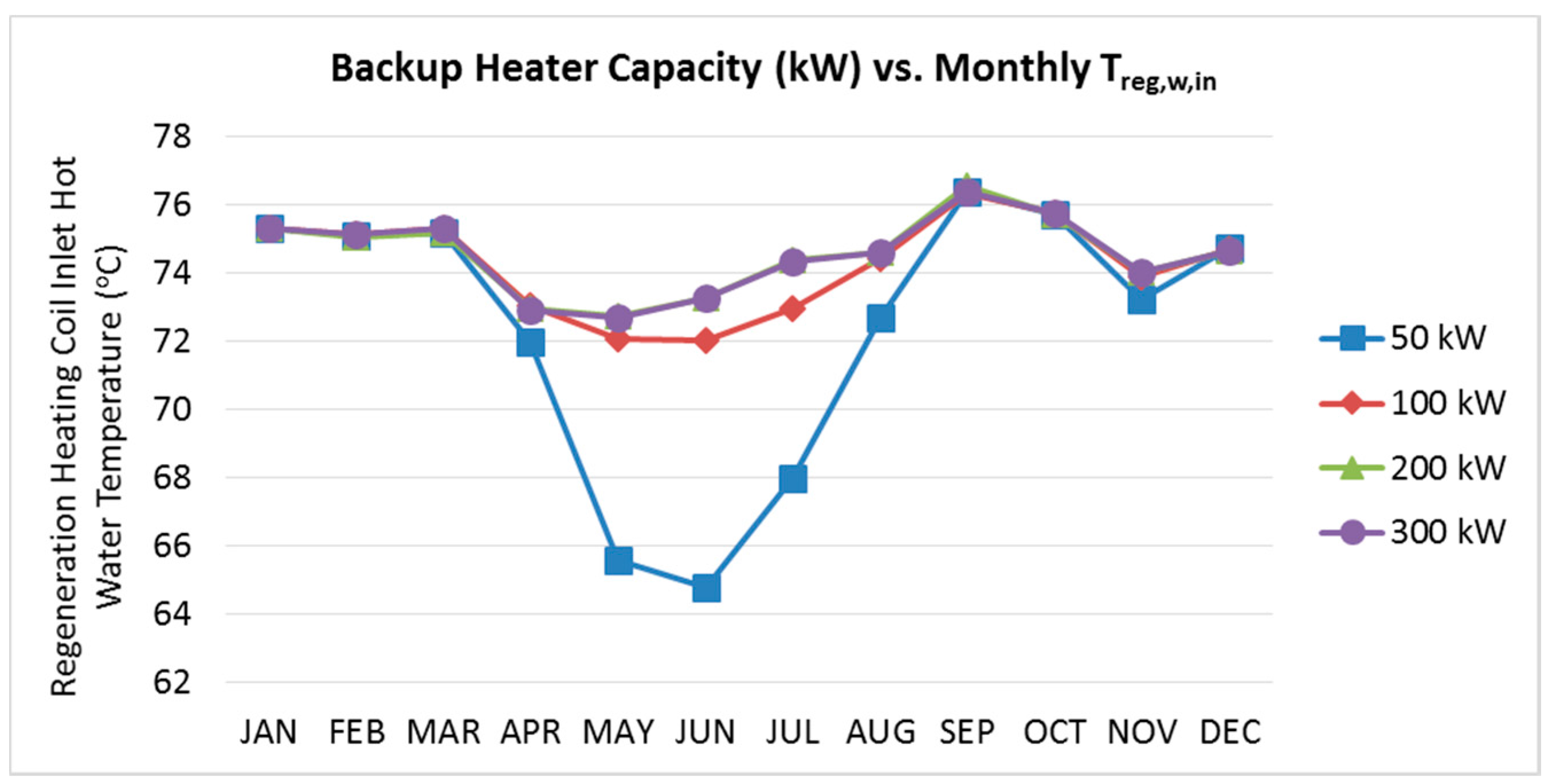
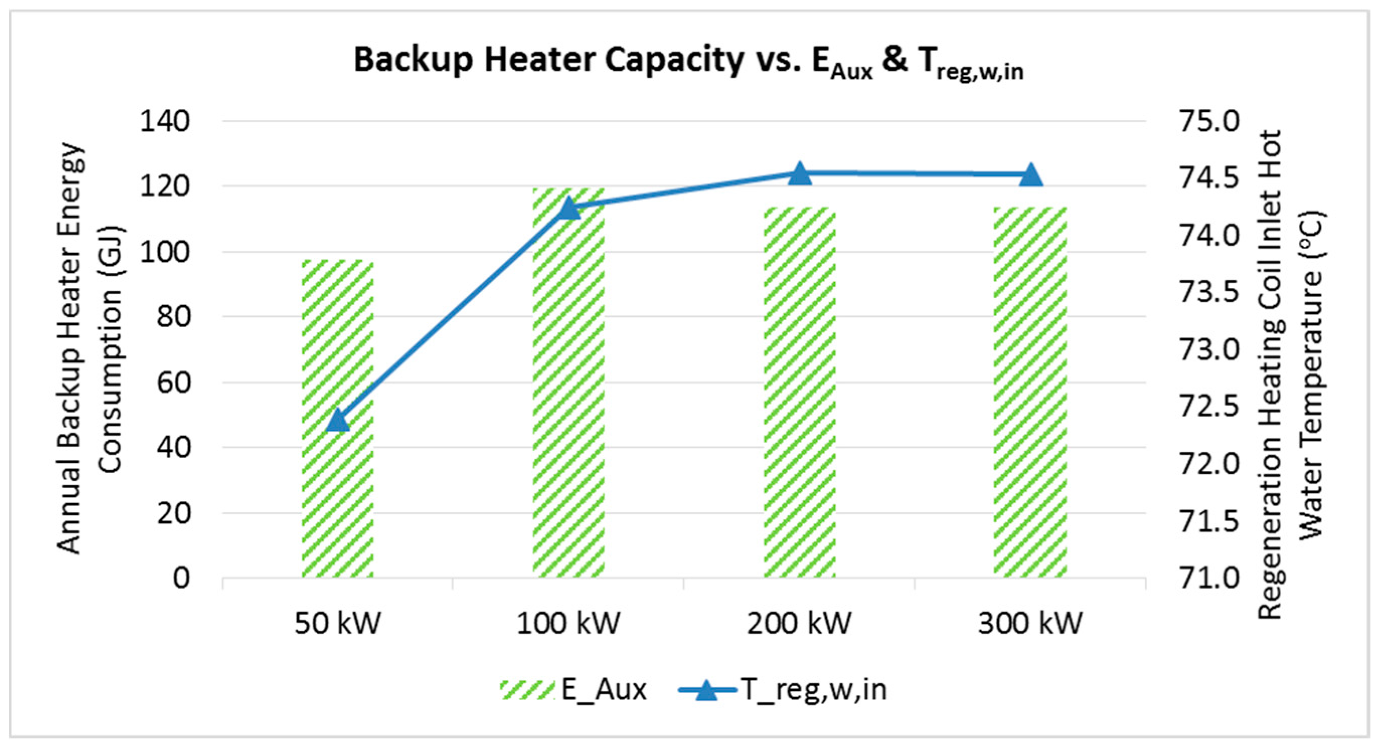
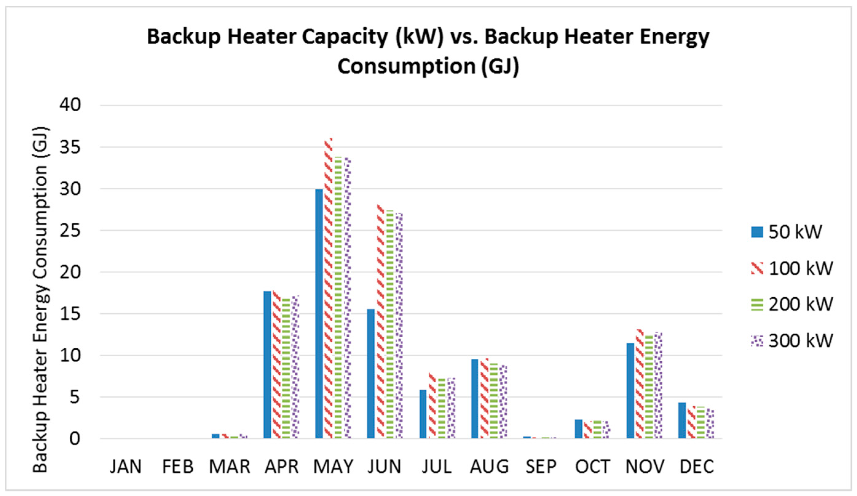
In relation to the backup heater capacity, 100 kW heater capacity appeared to be preferable, which could satisfy the 75 °C design regeneration heating coil hot water inlet temperature set-point with relatively low backup heater electricity consumption of 119 GJ annually. However, more than 100 kW backup heater capacity would not apparently influence the regeneration heating coil hot water inlet temperature and the backup heater energy consumption.
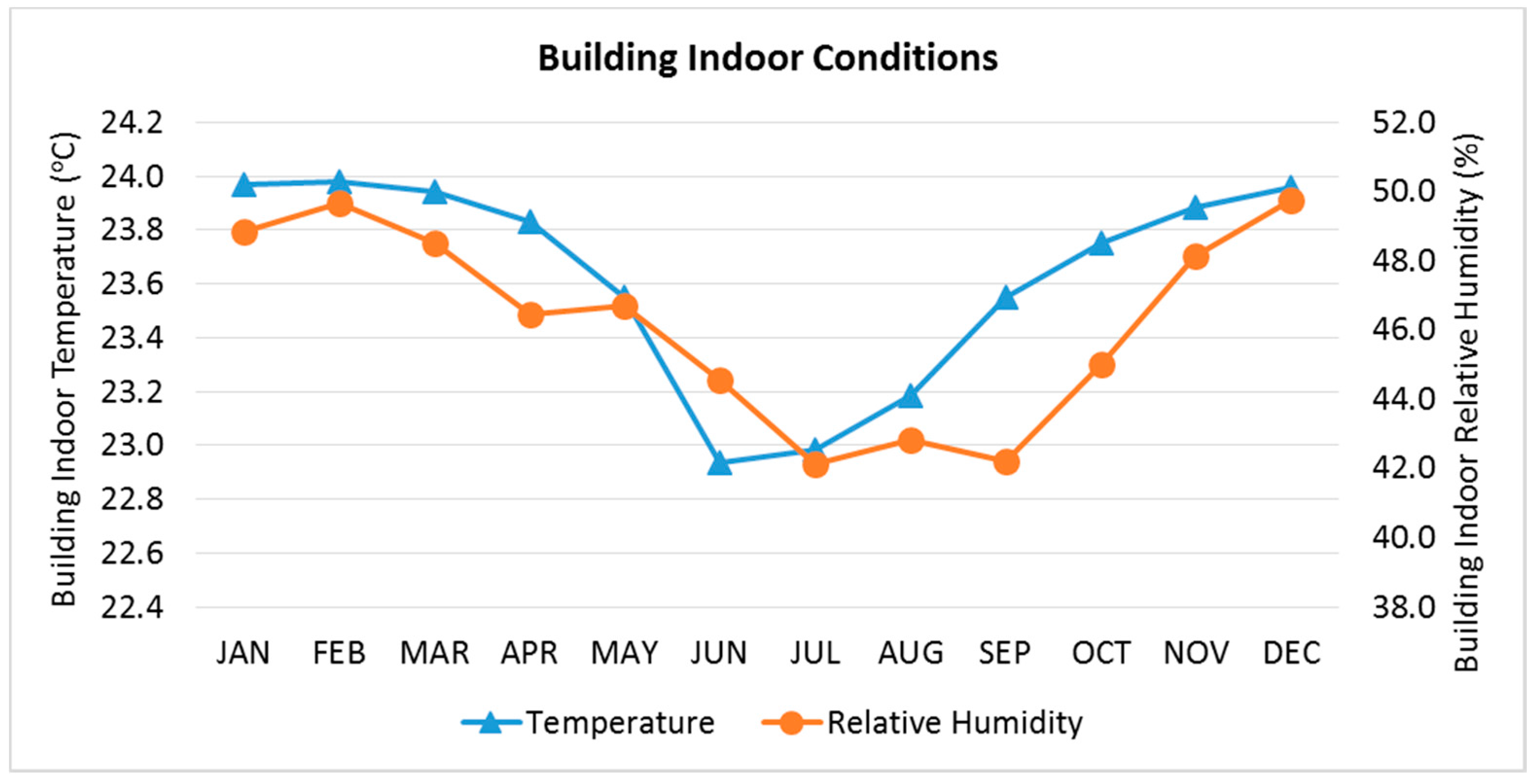
Finally, increasing the outdoor air humidity ratio actuator set-point for dehumidification control would dramatically reduce backup heater energy consumption perhaps at the expense of indoor thermal conditions. An outdoor air humidity ratio control set-point of 0.008 kgWater/kgDryAir was more reasonable, which could achieve both low backup heater energy consumption and good indoor thermal conditions with only 3.7% time set-point not met during occupied cooling.


