2.1. Demand Relief
Maintaining generation-demand balance is of great importance for the stable and reliable operation of a power system. This can be achieved by controllable resources on both the supply and demand sides [
17].
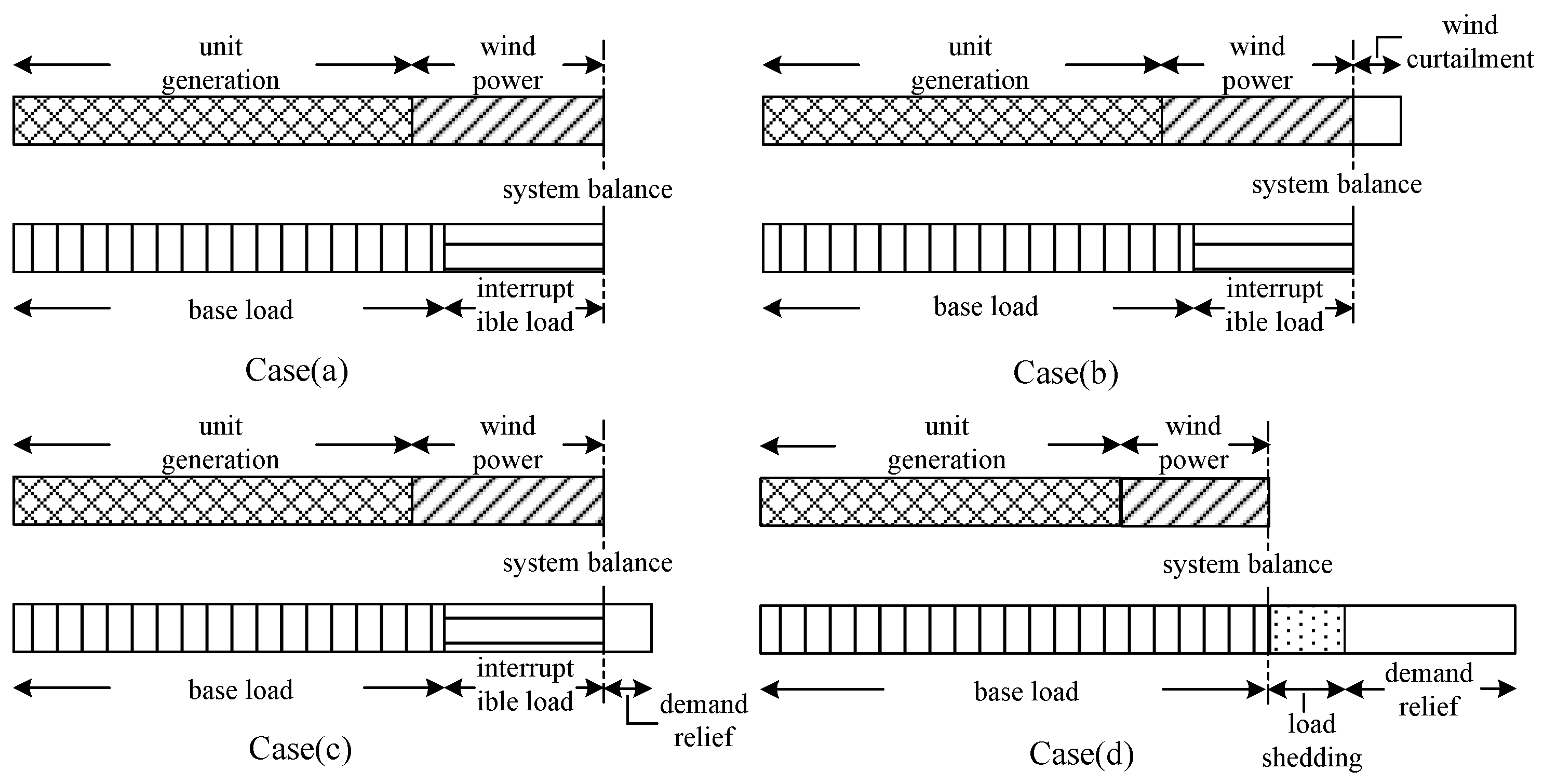
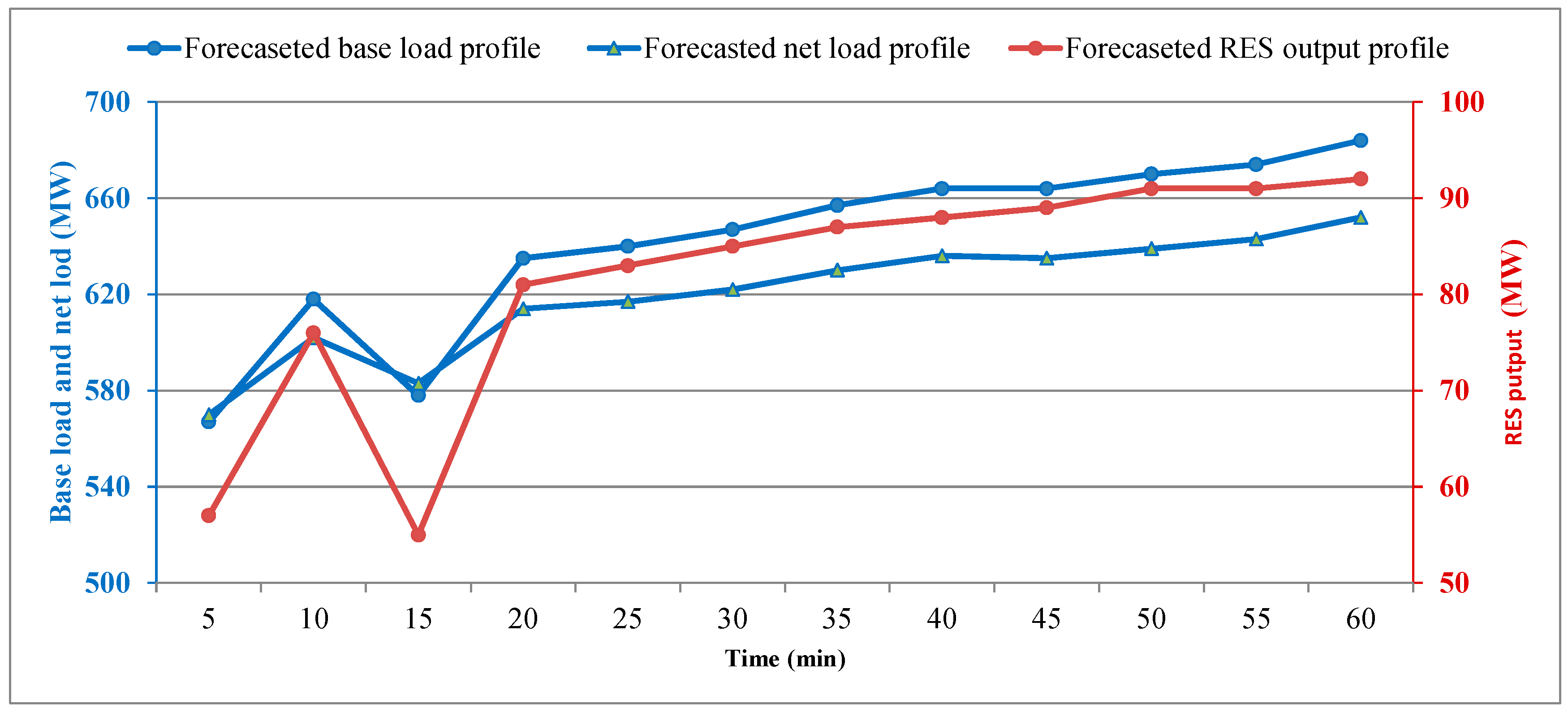
Figure 1 presents intuitively how a power system with RES keeps balance with the aids of interruptible load in different cases.
Case (a) represents the general situation where the ISO can maintain the balance by adjusting unit generation without reducing RES output or cutting load. When an imbalance materializes as an excess of supply to meet the demand, RES output reduction (e.g., wind curtailment) or conventional generation output reduction may be performed to reduce the supply, as Case (b) shows. On the other hand, if the imbalance materializes as a lack of supply to meet the demand, deployment of reserved conventional units or demand relief from LSEs is required, as Case (c) shows. However, when the deployment of reserved capacity plus the demand relief from all LSEs is still insufficient to cover the supply shortage, base load shedding is performed, as expressed by Case (d). Unlike elastic IL, the value of lost base load is relatively large since the base load is regarded as inelastic and crucial. To avoid such cost, more ILs should be explored as an effective and economical way to maintain system balance.
2.2. Flexible Ramping Product
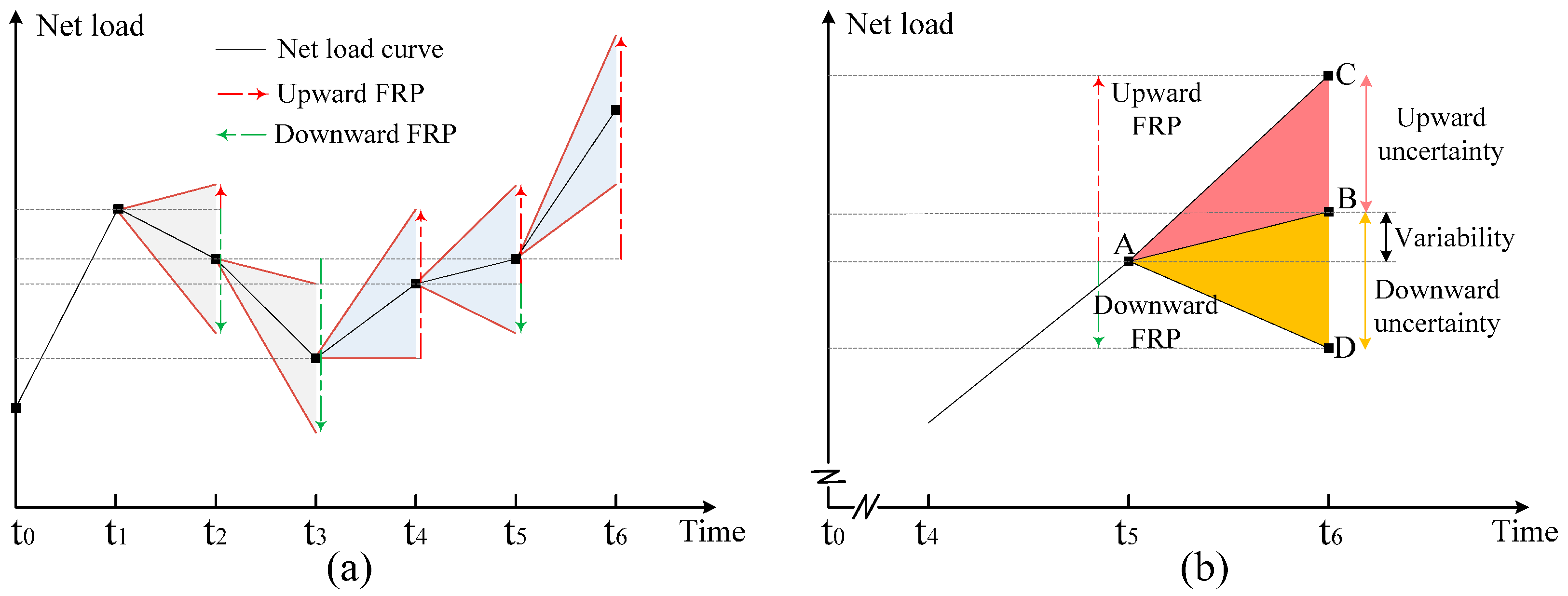
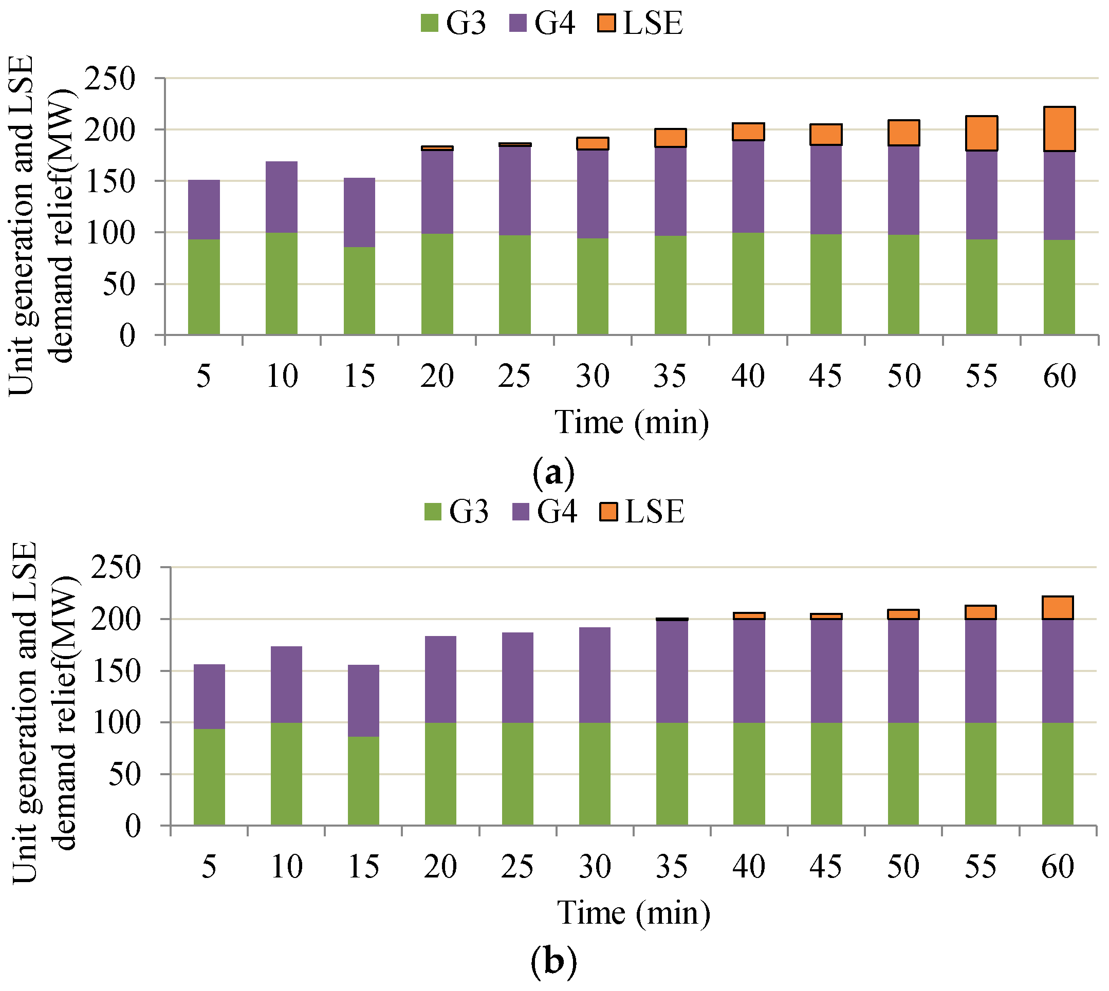
FRP targets the net load movement in RT operations and can be separated into two independent products based on the direction, namely upward FRP and downward FRP. The total FRP provided by all controllable resources should meet the system ramp need. The system-level ramp capability requirements are set for both upward and downward directions for each interval in RT dispatch and can vary between different intervals, as shown in
Figure 2a. Note that in t
5, there is only requirement for upward FRP because the net load is expected to increase steeply in this period and no downward FRP is needed. In contrast, only requirement for downward FRP is needed in t
2 and for other intervals such as t
1 and t
4, FRPs for both directions are required. Take t
4 for example, more details are presented in
Figure 2b, indicating that ramp capability requirements are composed of the net load variability and surrounding uncertainty. The variability and uncertainty caused by RES raise the requirements and intensify the issue of insufficient ramp capability. Therefore, more controllable resources such as IL are required to be introduced as FRP providers.
The deployment of FRP is embedded into the RT dispatch model. Cleared FRP is reserved at the current interval in order to meet the ramp capability requirement. When energy is dispatched for the next interval, FRP is naturally deployed as energy. Unlike traditional ancillary services whose prices are based on offers, FRP is priced at the opportunity cost for not providing energy and capped by the demand curves [
2] prescribed by the ISO. For example, MISO currently adopts a single-step demand curve with the ceiling price being 5
$/MWh [
18].
In order to present the technical characteristics of FRP, comparisons between FRP and other traditional ancillary services (e.g., regulation and operating reserve) are made in
Table 1. FRP is distinguished from regulation and operating reserve in product function, dispatch process, price level and technical requirement. Among these services, regulation has the most rigorous requirement for technologies such as respond speed. For instance, only a quarter of resources in MISO are eligible to provide regulation [
19]. On the other hand, providers of operating reserve should be capable of raising their output to the targeted level in required time. In contrast, the technical requirement for providing FRP is the lowest, and any real-time dispatchable resource can provide FRP according to CAISO’s market rule [
1]. Although the conventional generators are the only eligible providers of FRP currently in practice, other resources such as demand response can also provide such ramping capability in the RT. Actually, exploring demand-side flexibility could be a better choice if an efficient and reliable demand-side management (DSM) is reached. This is the case because unlike generators which are constrained by ramp rate limits, IL customers can turn off high-power electrical appliances such as heat pump and air conditioner in a very short time. Furthermore, the cost of demand-side resources providing such ramping capability is more effective than conventional generators as demand side is playing increasingly important role in today’s electricity markets. MISO is planning to utilize demand response resources (DDRs) to providing up-ramping capacity by reducing their loads [
20].
2.3. Stochastic RTUC Considering System Ramping Requirement and IL Provision
In the RT operation, the ISO endeavors to not only maintain the instantaneous balance, but also to arrange adequate resources to follow the possible net load changes in the near future. Its controllable resources include conventional units and ILs. To cope with the uncertainty of loads and RES outputs, stochastic RTUC is modeled with consideration of system ramping requirement and IL provision. Scenario simulation is performed based on the forecasted load and RES output, and takes both the precision and the tractability of the model into account [
21]. The simulation process is mainly composed of scenario generation and reduction, which are based on the Latin hypercube sampling (LHS) method [
22] and the fast forward selection algorithm [
23], respectively. The temporal and spatial dependency of forecasting errors are not examined. Instead, the base load and RES output are both modeled as specific statistical distributions attained from historical data, and typical scenarios are then generated and selected.
Based on the latest forecasts, the proposed model gives a resolution of the intra-hour dispatching strategy. The model considers the selected scenarios and minimizes the expected operating costs over all these scenarios. The unit commitment (UC) model structure is modified based on [
24] and is enhanced to include ramping requirement and IL provision:
where
cgen is the cost for start-up and operation of units,
creward is the cost for rewarding LSEs to provide demand-side services (i.e., FRP and demand relief), and
cpenalty is the penalty for base-load shedding and RES output curtailment.
The cost of units
cgen is expressed as
The first term in (2) represents the commitment schedule, in which is the start-up cost of unit g and is only active when the binary start-up variable yg,t is equal to 1. This part is common for all scenarios. The second term indicates the expected operation cost over all selected scenarios. Δt is the clearing granularity rated in minutes. ρs is the probability of scenario s. Cg(Pg,t,s) is the operation cost function of the generation output Pg,t,s.
The cost for rewarding LSEs is given as
In (3), J is the set of all LSEs with index j. λCAP is the compensation to LSEs for providing demand-side resource, which is similar to operating reserve and can provide additional capacity (i.e., ) in the event that units have to reduce their output or be taken offline. is the reward to LSE j for providing unit demand relief and is negotiated by the ISO and LSE j in their specific IL contract, and Δ is the amount of demand relief provided by LSE j in period t under scenario s. λFRP is the system-level demand price of FRP set by the ISO, and is the awarded upward FRP capacity of LSE j in period t under scenario s. The main difference between demand relief and FRP is that demand relief is the realized load shedding, while FRP is the deductible capability reserved for the next interval.
cpenalty is composed of the cost for base-load shedding and RES output curtailment penalty, and described by
where
ν is the value of lost base load, Δ
is the amount of lost base load in period
t under scenario
s.
φ is the penalty for unit RES output curtailment,
Dw,t,s is the amount of curtailed output of RES
w in period
t under scenario
s.
The objective function in (1) is subject to general UC constraints and FRP-related constraints. The general UC constraints include unit ramping up/down limits, unit generation limits, the maximum limits on base load shedding and RES output curtailment, and power balance constraint [
5,
25]. The FRP-related constraints reflect the system-wide ramp capability requirement, the impacts of FRP on unit generation and the maximum limits on interruptible load shedding. All constraints are categorized and listed as follows:
Output bounds of generating units
Ramping limits of generating units
Limits on base-load shedding and RES output curtailment
Power balance and ramp capability requirement
Constraints (5) and (6) enforce the output bounds of units where () is the maximum (minimum) output of unit g, xg,t is the on/off state variable of unit g, and () is the upward (downward) FRP provided by unit g in period t under scenario s. It is notable that since the FRP is the focus of this work, provisions of other services (e.g., regulation and operating reserve) are not considered for simplicity. Constraints (7) and (8) restrict the change in the output of units between two contiguous time periods within their maximum ramp capabilities. Note that () is the upward (downward) ramping rate of unit g. Constraints (9) and (10) ensure that a unit’s provision of FRP does not exceed its ramp capability over the dispatching interval.
The amount of acceptable base-load shedding is capped with constraint (11) where is the base load without shedding. Similar rationale applies for RES output curtailment as shown in constraint (12), in which Pw,t,s is the RES output without curtailment. In terms of IL, Constraint (13) imposes that a LES’s total provision of demand relief and FRP should not exceed its overall capacity.
Constraint (14) enforces the system generation-demand power balance. Constraints (15) and (16) define the system-level ramp capability requirements which are composed of the forecasted net load variability (Δ
) and additional uncertainty. The magnitude of surrounding uncertainty (
and
), as explained in
Section 2.2, can be constant based on the system scale [
26] or is the function of forecasted load and RES output [
5]. Finally, constraint (17) points out the positive variables.


