Article

Estimation of the Relative Arrival Time of Microseismic Events Based on Phase-Only Correlation

1
Key Laboratory of Exploration Technologies for Oil and Gas Resources (Yangtze University), Ministry of Education, Wuhan 430100, China
2
Key Laboratory of Shale Gas and Geoengineering, Institute of Geology and Geophysics, Chinese Academy of Sciences, Beijing 100029, China
*
Author to whom correspondence should be addressed.
Energies 2018, 11(10), 2527; https://doi.org/10.3390/en11102527
Submission received: 29 April 2018 / Revised: 1 September 2018 / Accepted: 19 September 2018 / Published: 21 September 2018
(This article belongs to the Special Issue Unconventional Natural Gas (UNG) Recoveries 2018)

Abstract

:
The arrival time of a microseismic event is an important piece of information for microseismic monitoring. The accuracy and efficiency of arrival time identification is affected by many factors, such as the low signal-to-noise ratio (SNR) of the records, the vast amount of real-time monitoring records, and the abnormal situations of monitoring equipment. In order to eliminate the interference of these factors, we propose a method based on phase-only correlation (POC) to estimate the relative arrival times of microseismic events. The proposed method includes three main steps: (1) The SNR of the records is improved via time-frequency transform, which is used to obtain the time-frequency representation of each trace of a microseismic event. (2) The POC functions of all pairs of time-frequency representations are calculated. The peak value of the POC function indicates the similarity of the traces, and the peak position in the time lag axis indicates the relative arrival times between the traces. (3) Using the peak values as weighting coefficients of the linear equations, consistency processing is used to exclude any abnormal situations and obtain the optimal relative arrival times. We used synthetic data and field data to validate the proposed method. Comparing with Akaike information criterion (AIC) and cross-correlation, the proposed method is more robust at estimating the relative arrival time and excluding the influence of abnormal situations.

1. Introduction

Microseismic monitoring is widely used to predict rockbursts in coal mining, minimize the risks of CO2 leakage, characterize geothermal energy reservoir, and evaluate hydraulic fracturing [1,2,3,4,5,6,7,8]. The arrival time of microseismic event is an important piece of information of microseismic monitoring for phase identification, source location, source mechanism analysis, and microseismic interpretation [9,10,11,12,13]. The arrival time is often identified by a change from background noise [14]. Multiple attributes of the record are used to identify the arrival time, including the amplitude, energy, frequency content, and polarization. The ratio of the short-term average over long-time average (STA/LTA) is the most commonly used algorithm for identifying arrival times [15]. This method is sensitive to background noise and the length of the window [16]. Some modified algorithms have been proposed, such as modified energy ratio, recursive STA/LTA, and characteristic function preprocessing [17,18,19,20,21]. The Akaike Information Criterion (AIC) assumes that a time series can be broken down into two pseudo-stationary segments. A pseudo-stationary segment has unchanging mean, variance, and autocorrelation [22,23]. The properties of higher-order statistic parameters, such as kurtosis or skewness, have also been used to detect the arrival time [24]. Many time-frequency approaches for picking arrival times have been proposed, such as continuous wavelet transform, synchrosqueezed continuous wavelet transform, empirical mode decomposition, and Cohen’s class distribution [25,26,27,28]. Coherence-based methods have been used to estimate the relative arrival time among traces. Artificial neural network, entropy function, and image processing method were used to pick arrivals automatically [29,30,31]. With the development of machine learning, some unsupervised and supervised algorithms were used to detect the arrival times of microseismic events [32,33]. Since a single method may fail in accurately identifying arrival times, several hybrid methods have been proposed. Zhang et al. designed a method that combines AIC and wavelet transform [34]. Saragiotis et al. discussed a hybrid method that combines the advantages of the coherence method and time-frequency analysis [35]. Akram and Eaton proposed an STA/LTA-AIC hybrid approach [36]. Li et al. used empirical mode decomposition to improve the signal-to-noise ratio of record and applied AIC to pick the arrival times [37].
It is well known that a low signal-to-noise ratio of record remains a challenge for accurate arrival time identification. Meanwhile, real-time microseismic monitoring has been widely applied. Due to the high sample rate, real-time monitoring may generate a vast number of continuous records. In addition, abnormal situations of monitoring equipment may arise in the field (for example, abnormal geophone coupling, damaged transmission lines, or geophone faults). These factors render arrival time identification more complex. Accuracy and efficiency become two important indicators of the arrival time identification method. Therefore, we propose a new method based on phase-only correlation (POC) to estimate the relative arrival times of downhole microseismic data.
It is hard to know the accurate origin time of microseismic events before source location [38]. This means that the travel times of microseismic events cannot be directly converted from the arrival times. Thus, the relative arrival times are of more practical value for monitoring processing. Due to similar source locations and focal mechanisms, a cluster of seismic events show similar waveforms on the record [39]. Correspondingly, the traces of one event recorded by a geophone array also reveal waveform similarity. Coherence-based methods can be used to pick the relative arrival times with the information of multi-trace records [40,41,42]. The proposed method applies POC to estimate the relative arrival time. Previously, POC was an image-matching method for fingerprint identification [43]. POC evaluates the similarity level by calculating the peak value of the cross-phase spectrum of two two-dimensional (2D) images. Later, POC was applied to identify the similarity of seismic events, diagnose complex diseases, and detect microseismic events [44,45,46]. The two main properties of the POC are as following: (1) the POC function is not influenced by the intensity difference of data because POC only uses the phase information of data; and (2) the peak position of POC will shift when one image is shifted, and the peak value is invariant [44]. So, we can estimate relative arrival time among the traces by detecting the position of the peak value. Meanwhile, the peak values of the POC are used as weighting coefficients to improve the consistency of estimated relative arrival times and exclude the interferences of abnormal situations.
We used synthetic data and a high signal-to-noise ratio (SNR) microseismic event to validate the proposed method. Firstly, we used synthetic data to validate the proposed method. Secondly, we used a high SNR microseismic event to generate three testing datasets by adding different noise levels to the microseismic event and replacing one trace of the event with background noise to simulate abnormal situations. Lastly, AIC, cross-correlation, and POC were used to calculate the relative arrival times of the two testing datasets. Moriya used moving time window spectral estimation (that is, short time Fourier transform (STFT)) for POC [44]. Zhang replaced the STFT with Wigner-Ville distribution (WVD) to overcome the low resolution of STFT [47]. We used these two time-frequency transforms to implement the POC function and named them POC (STFT) and POC (WVD), respectively. The list of symbols used in this article is given in Table 1.

2. Methodology

2.1. Time-Frequency Transform

Given the two traces of a microseismic event, R 1 ( n ) and R 2 ( n ) , suppose that the waveforms of two traces are identical expect for the time shifting, and the arrival time difference of this two traces is n delay (that is, R 2 ( n ) = R 1 ( n + n delay ) ).
Using Wigner-Ville distribution (WVD) [48], the time-frequency representations of the two time series are obtained. Suppose that the time-frequency representations of R 1 and R 2 are f ( n , ω ) and g ( n , ω ) , respectively.
f ( n , ω ) = 2 k = R 1 ( n + k ) R 1 ( n k ) e j 2 k ω g ( n , ω ) = 2 k = R 2 ( n + k ) R 2 ( n k ) e j 2 k ω
where n is time, ω is angular frequency, k is time shifting, R * denotes the complex conjugate of R .

2.2. Phase-Only Correlation

2D discrete Fourier transform is performed to obtain the cross-phase spectrum [43,44].
F ( k 1 , k 2 ) = n = m 1 m 1 ω = m 2 m 2 f ( n , ω ) e j 2 π k 1 n N 1 e j 2 π k 2 ω N 2 = A F ( k 1 , k 2 ) e j θ F ( k 1 , k 2 )
G ( k 1 , k 2 ) = n = m 1 m 1 ω = m 2 m 2 g ( n , ω ) e j 2 π k 1 n N 1 e j 2 π k 2 ω N 2 = A G ( k 1 , k 2 ) e j θ G ( k 1 , k 2 )
where k 1 = m 1 m 1 and k 2 = m 2 m 2 . The sizes of f ( n , ω ) and g ( n , ω ) are N 1 N 2 = ( 2 m 1 + 1 ) ( 2 m 2 + 1 ) . F ( k 1 , k 2 ) and G ( k 1 , k 2 ) denote the 2D discrete Fourier transform (DFT) of f ( n , ω ) and g ( n , ω ) , respectively. A F ( k 1 , k 2 ) and A G ( k 1 , k 2 ) are amplitude components. e j θ F ( k 1 , k 2 ) and e j θ G ( k 1 , k 2 ) are phase components.
The cross-phase spectrum R ^ F G ( k 1 , k 2 ) between F ( k 1 , k 2 ) and G ( k 1 , k 2 ) is defined as:
R ^ F G ( k 1 , k 2 ) = F ( k 1 , k 2 ) G ¯ ( k 1 , k 2 ) | F ( k 1 , k 2 ) G ¯ ( k 1 , k 2 ) | = e j ( θ F ( k 1 , k 2 ) θ G ( k 1 , k 2 ) )
where G ¯ ( k 1 , k 2 ) denotes the complex conjugate of G ( k 1 , k 2 ) .
The POC function r ^ f g ( n , ω ) is obtained by using the inverse 2D discrete Fourier transform of R ^ F G ( k 1 , k 2 ) .
r ^ f g ( n , ω ) = 1 N 1 N 2 k 1 = m 1 m 1 k 2 = m 2 m 2 R ^ F G ( k 1 , k 2 ) e j 2 π k 1 n N 1 e j 2 π k 2 ω N 2  
where n denotes the time lag and ω denotes the frequency lag.
The range of r ^ f g ( n , ω ) is from 0 to 1. When f ( n , ω ) and g ( n , ω ) are similar, the POC function r ^ f g ( n , ω ) exhibits a distinct sharp peak. The position of the peak value (the maximum value of the POC function) is located at the center point of r ^ f g ( n , ω ) . When f ( n , ω ) and g ( n , ω ) are not similar, the peak drops obviously [43]. Therefore, the peak value of the POC can be used to indicate the similarity between f ( n , ω ) and g ( n , ω ) .
According to the arrival time difference in the time domain between the two traces, the time shifting of the event in the time-frequency domain is n delay (that is, g ( n , ω ) = f ( n + n delay , ω ) ). By using the time-shift property of DFT, the POC function between f ( n , ω ) and g ( n , ω ) can be given by:
r ^ f g ( n , ω ) = 1 N 1 N 2 k 1 = m 1 m 1 k 2 = m 2 m 2 R ^ F G ( k 1 , k 2 ) e j 2 π k 1 n N 1 e j 2 π k 2 ω N 2 = 1 N 1 N 2 k 1 = m 1 m 1 k 2 = m 2 m 2 e j ( θ F ( k 1 , k 2 ) θ F ( k 1 , k 2 ) ) e j 2 π n d e l a y n N 1 e j 2 π k 1 n N 1 e j 2 π k 2 ω N 2 r ^ f f ( n n d e l a y , ω )
As previously described, the only difference between R 1 ( n ) and R 2 ( n ) is the time shifting n delay , and the peak value of the POC function r ^ f f ( n , ω ) is located in the center point. So, Equation (6) implies that the position shifting between the peak value of r ^ f g ( n , ω ) and the peak value of r ^ f f ( n , ω ) in the time lag axis can indicate the time shifting between R 1 ( n ) and R 2 ( n ) . Therefore, the relative arrival times can be estimated by detecting the peak location of the POC. It is obvious that the position shifting of the peak value in the frequency lag axis can indicate the main frequency shifting between R 1 ( n ) and R 2 ( n ) . To suppress the interferences in the time-frequency domain, we performed a low-pass filtering for the cross-phase spectrum with a 2D Hamming window.

2.3. Consistency Processing

Let t i and t j be the arrival time of the ith and jth traces, respectively. Then, the arrival time difference Δ t i j can be given by:
Δ t i j = t i t j  
Due to noise interference or abnormal situations of monitoring equipment, the relative arrival times are not always consistent (for example, Δ t 12 Δ t 23 Δ t 13 ). Meanwhile, in the normal situation, there are high similarities among the traces of a microseismic event record. The peak value of POC is high. If the waveform of one trace is abnormal (this implies the abnormal situations of monitoring equipment), the similarities will be low between this trace and other normal traces. Accordingly, the peak value of the POC will be low. So, in order to improve the consistency of the estimated values of relative arrival time and exclude the influence of abnormal situations, we used the over-determined linear equations to obtain the optimal result [39].
The peak values of the POC functions are added into Equation (7) (shown as Equation (8)).
r i j Δ t i j = r i j ( t i t j )  
where r i j denotes the peak value of the POC between the ith and jth traces and Δ t i j denotes the arrival time difference obtained using POC.
Although Equation (8) is identical to Equation (7) for a single pair of traces, we can obtain the optimized result of arrival times by using all pair of traces to construct linear equations (shown as Equation (9)).
[ r 12 r 12 0 0 r 13 0 r 13 0 r 14 0 0 r 14 0 r 23 r 23 0 0 r 24 0 r 24 0 0 r 34 r 34 1 1 1 1 ] [ t 1 t 2 t 3 t 4 ] = [ r 12 Δ t 12 r 13 Δ t 13 r 14 Δ t 14 r 23 Δ t 23 r 24 Δ t 24 r 34 Δ t 34 0 ]  
where t i denotes the optimized relative arrival time. The mean of the optimized relative arrival times must be equal to zero (that is, t 1 + t 2 + t 3 + t 4 = 0 ). Then, t 1 t 4 are actually the relative arrival times, not the arrival times in the corresponding traces.
As shown in Figure 1, the workflow of the proposed method consists of three main steps: (1) calculating the time-frequency representations of traces; (2) using the POC function of all pairs of traces to obtain peak values (or similarities between traces) and peak positions (or arrival time differences among traces); and (3) using weighting linear equations to obtain the optimal relative arrival times.

3. Synthetic Data Analysis

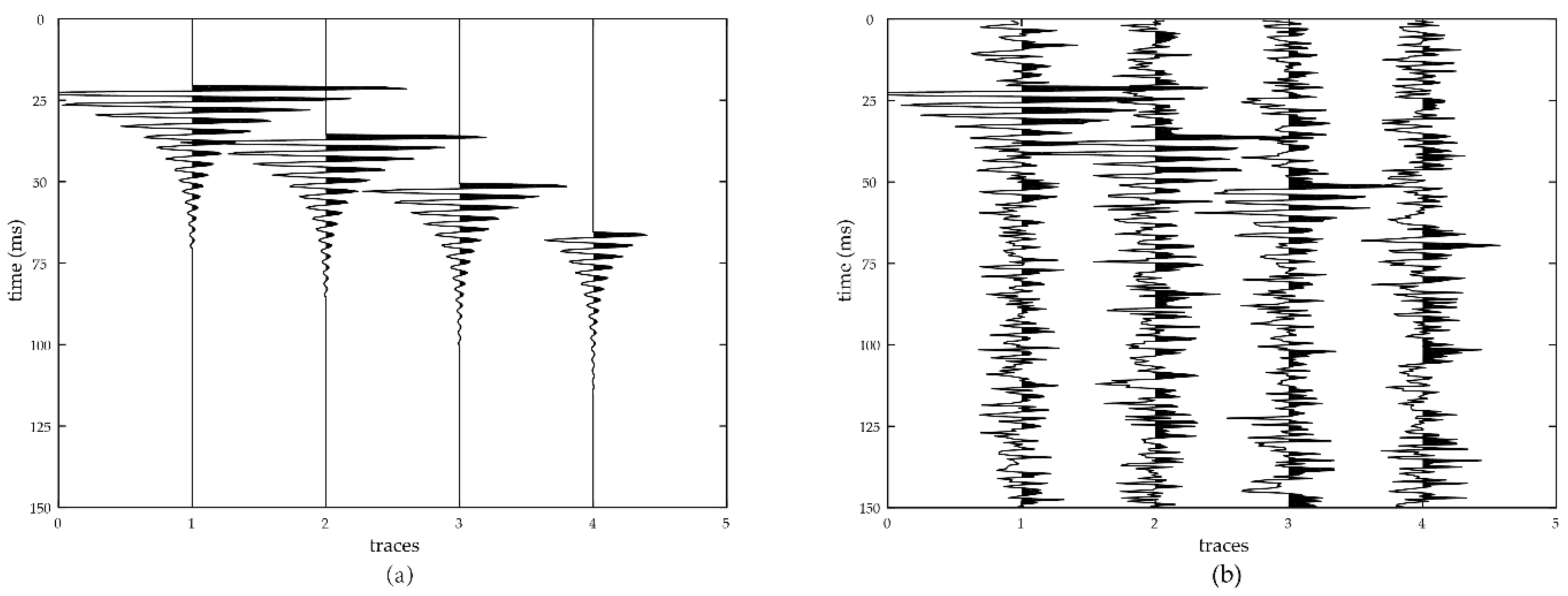
To validate the proposed method, we synthesized a record with four traces and a sampling of 0.5 ms (Figure 2a). Each trace included an exponential decaying sinusoidal signal, the frequency of which was 300 Hz. The length of a single trace was 150 ms (or 300 sampling points). The amplitude ratio of the four traces was set as 4:3:2:1, and the lag times of adjacent traces were set as 15 ms (or 30 sampling points). Then, we generated noisy data by adding Gaussian white noise to the previous record. The signal-to-noise ratio of the noisy data was 0 dB (Figure 2b).
The signal-to-noise ratio is defined as
S N R = 20 log 10 ( σ signal σ noise )  
where σ signal denotes the standard deviation of the signal and σ noise denotes the standard deviation of the noise.
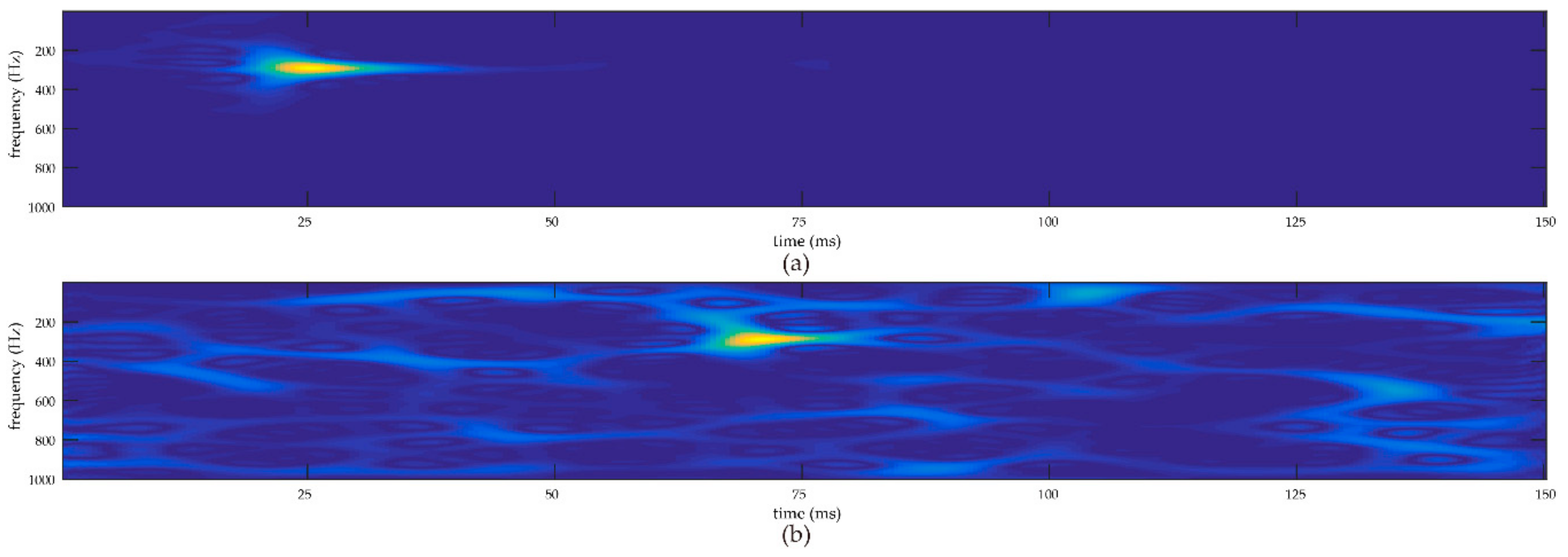
The first trace (or Trace 1) and the fourth trace (or Trace 4) of the noisy data were selected to illustrate the process of the proposed method. Figure 3 shows the time-frequency representations of Trace 1 and Trace 4 obtained using the Wigner-Ville Distribution. It was difficult to detect the sinusoidal signal of Trace 4 in the time domain. However, we were able to observe the signal in the time-frequency domain due to the time-frequency sparseness of this signal. So, using time-frequency transform can improve the signal-to-noise ratio of a record.
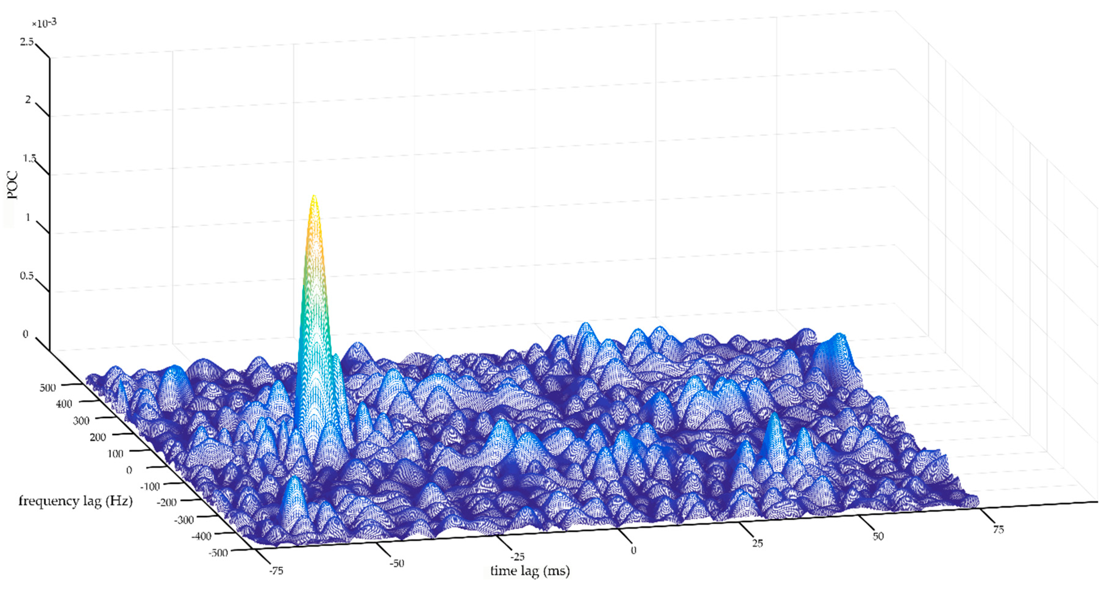
Figure 4 shows the POC between Trace 1 and Trace 4. There is a distinct peak in the POC function. The peak value is located at −45 of the time lag axis. The minus sign indicates that the arrival time of Trace 1 is ahead of that of Trace 4. The location of the peak value directly indicates the arrival time difference between Trace 1 and Trace 4. This result is consistent with the theoretical value. Meanwhile, it is clear that the peak value of the POC function in Figure 4 is less than 1. This result is attributed to the effect of the low-pass filtering for the cross-phase spectrum.
As shown in Figure 4, the range of the time lag axis is from −75 to 75, which is half the length of a single trace. If the arrival time difference between two traces were bigger than half the length of a single trace, the peak location would not directly indicate the arrival time difference, and we would have to recalculate to obtain the accurate arrival time difference based on the peak location, the periodicity property of Fourier transform, and other previously determined information. The analyzed data should be long enough to avoid this situation. For microseismic monitoring, the length can be estimated by using the prior information of the monitoring survey and the downhole velocity structure.
By calculating all of the pairs of traces, we can obtain all arrival time differences among all traces (Table 2).
The estimation of the relative arrival time of the noisy data was obtained after the consistency processing. The estimated relative arrival times of the four traces are −22.6 ms, −7.6 ms, 7.5 ms, and 22.8 ms, respectively. Comparing the theoretical values with the estimated values, the relative arrival time of the first trace was forced to zero. Then, the estimated relative arrival times were 0 ms, 15 ms, 30.1 ms, and 45.4 ms, respectively. If the relative arrival time of one trace is positive, it indicates that the arrival time of this trace is lagging behind that of the first trace. Otherwise, the arrival time of this trace is ahead of that of the first trace. As shown in Table 3, the estimated values of relative arrival times are highly consistent with the theoretical values. The maximum error is 0.4 ms, which is smaller than one sampling interval (0.5 ms). This result indicates that POC can be used to estimate the relative arrival time.

4. Field Data Analysis

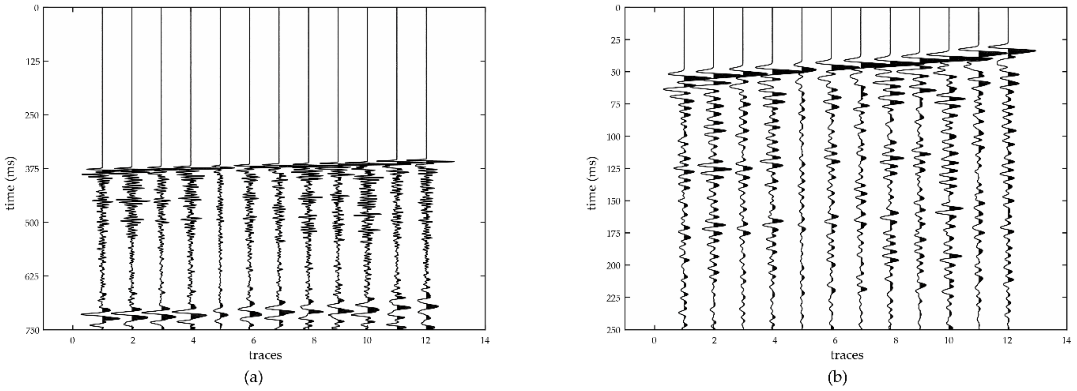
The studied microseismic event was acquired during a multi-stage hydraulic fracture treatment of a shale gas reservoir. A 12-level geophone array was used to record with a sampling of 0.25 ms in the monitoring well. The distance between the fracture stage and the geophone array was about 1500 m. The length of the record time was 750 ms (or 3000 sampling points). According to the waveforms of the event (Figure 5), it is obvious that the arrival time of the P-wave was at approximately 375 ms and the arrival time of the S-wave was at approximately 700 ms. The P-wave record of this event was intercepted from 325.25 ms to 575 ms (or 1000 sampling points) (Figure 5b).
Four methods (AIC, cross-correlation, POC (STFT), and POC (WVD)) were used to estimate the relative arrival times of the P-wave record.
The formula of AIC is defined as:
A I C ( i ) = i log ( var ( x [ 1 , i ] ) ) + ( n i 1 ) log ( var ( x [ i + 1 , n ] ) )  
where x ( i ) is the time series of one trace, n is the length of the trace, and v a r ( ) denotes the variance of a segment of x .
The estimated values of the first trace were forced to zero. Due to the high SNR of the microseismic event record (Figure 5), the four sets of calculation results had a high degree of consistency (Table 4).
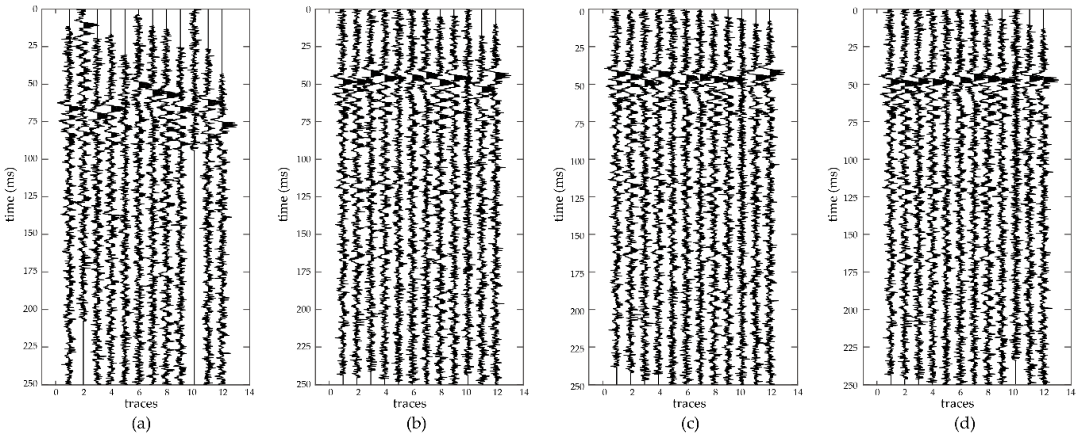
These results were used as adjusting value to eliminate the arrival time difference among the traces. As shown in the four subgraphs of Figure 6, it is obvious that the P-wave waveforms of the traces were flattened. Because the accurate arrival times of the field data were not known, the average values of the four sets of results were viewed as the theoretical relative arrival times (Table 4).
To simulate abnormal situations of monitoring equipment, we used background noise to replace the 10th trace of the P-wave record, then added three different level Gaussian white noises to the previous P-wave record (Figure 7).
Table 5 shows the peak value of the POC (WVD) for the first noisy data (Figure 7a). Each peak value corresponds to one pair of traces. The peak values related to the 10th trace are obviously smaller than others. This result is consistent with the fact that there is not a P-wave signal in the 10th trace. So, the peak value of the POC function was used to detect abnormal situations in the record.
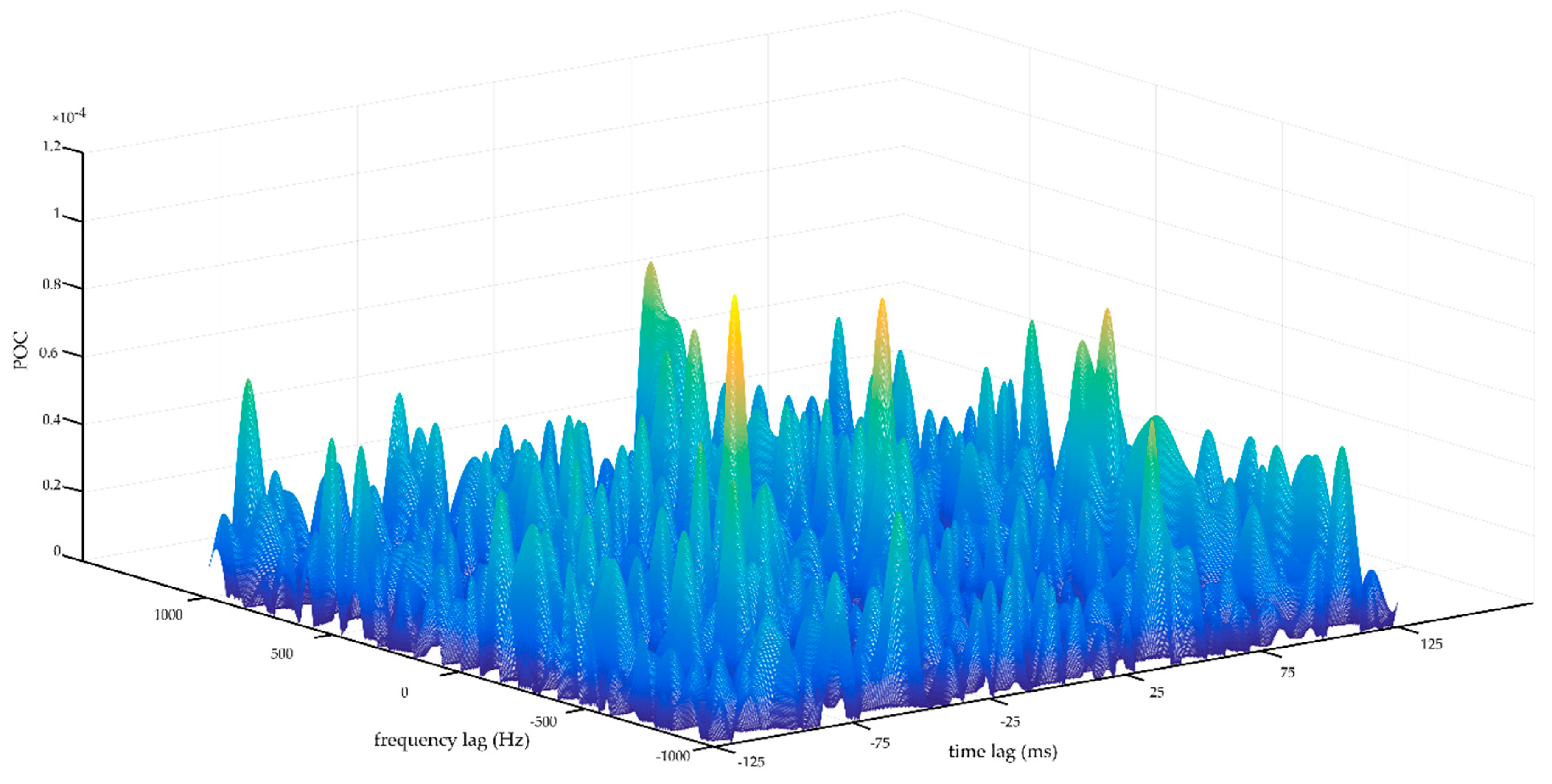
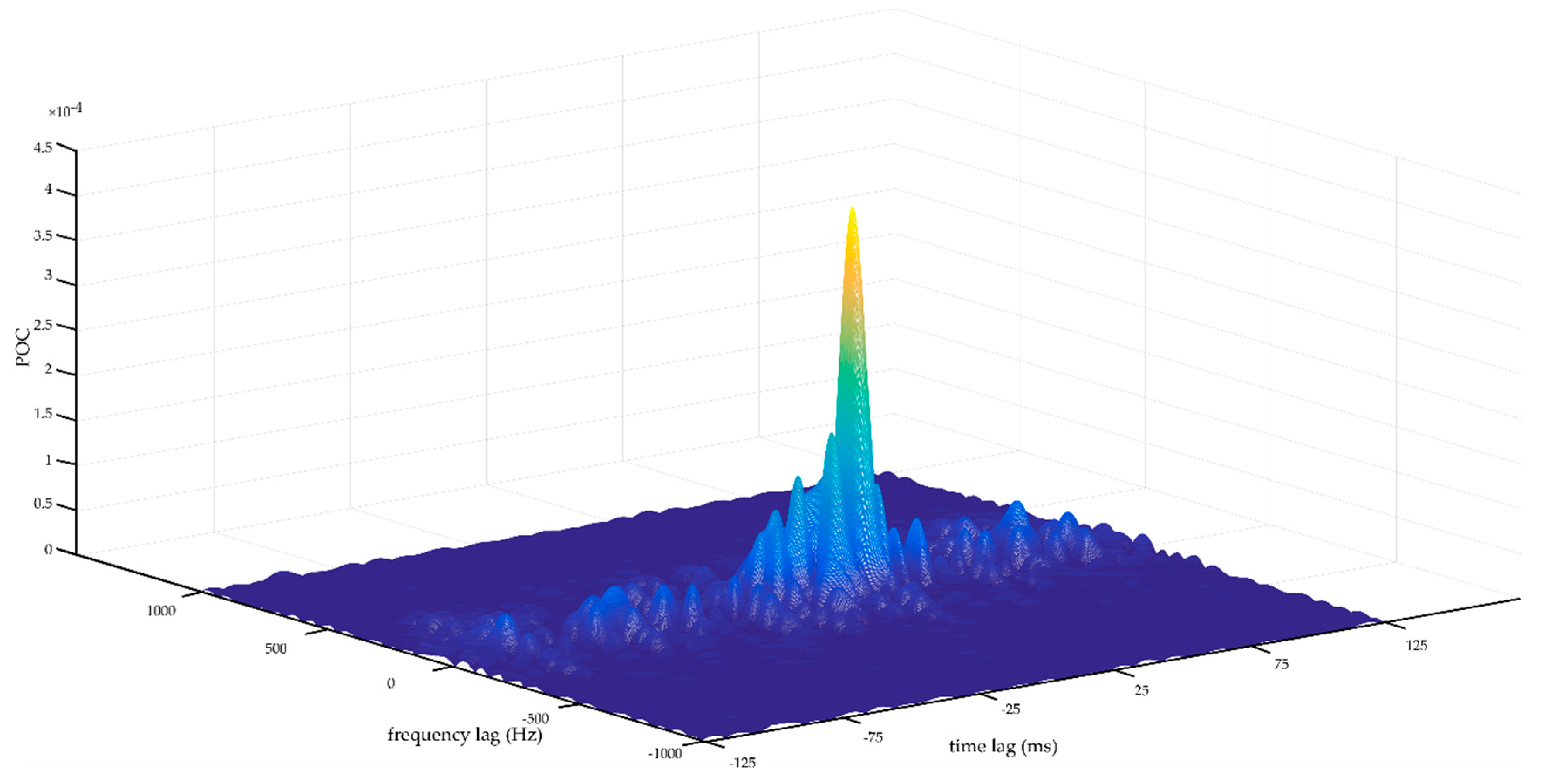
Figure 8 shows the POC function of the first trace and the 10th trace, and Figure 9 shows the POC function of the first trace and the 12th trace. Comparing Figure 8 with Figure 9, there is a distinct peak in Figure 9 that does not exist in Figure 8. Therefore, the peak value of the POC function is an important constraint to estimate the relative arrival time of microseismic event records.
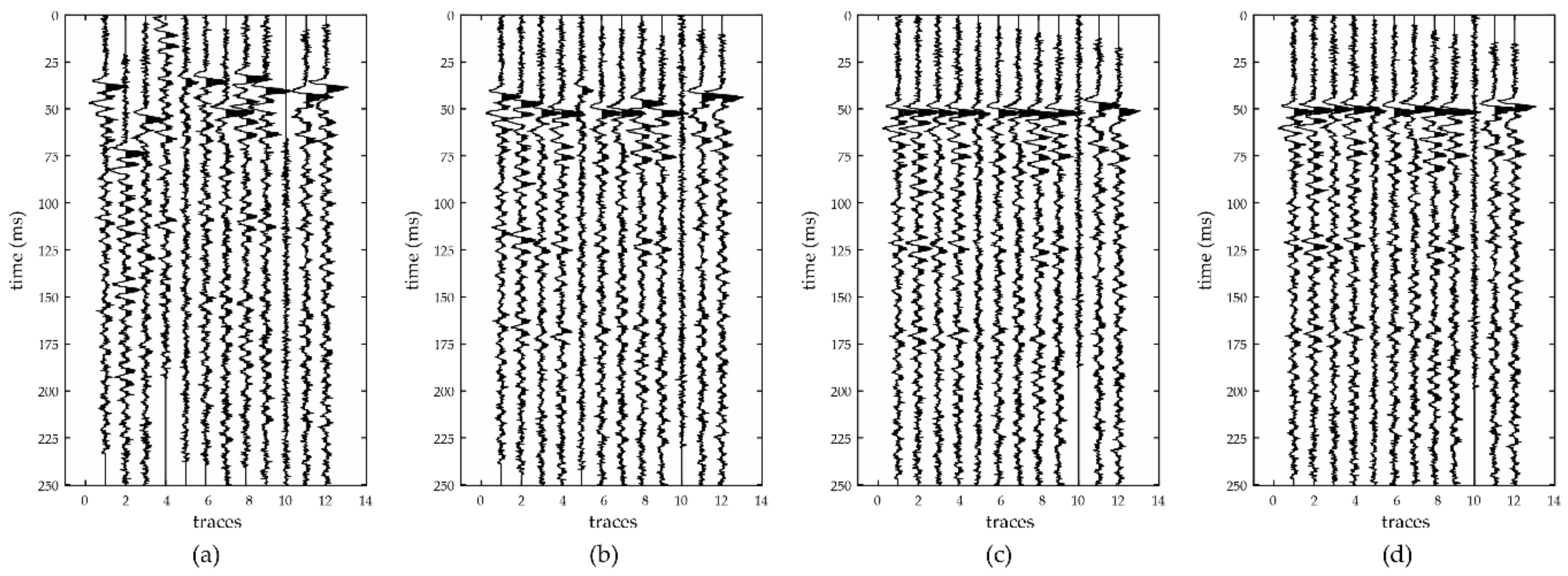
The estimated values of relative arrival times were obtained using the four methods (Table 6). Then, we used the estimated values to eliminate the arrival time differences of the first noisy dataset. As shown in Figure 10, the estimated values of AIC and cross-correlation cannot eliminate the arrival time differences among the traces. The 11th trace in Figure 10c is not consistent with other traces and the flattening effect of POC (WVD) is better than that of POC (STFT). Meanwhile, the estimated values of the 10th trace are random values for all four methods (Table 6).
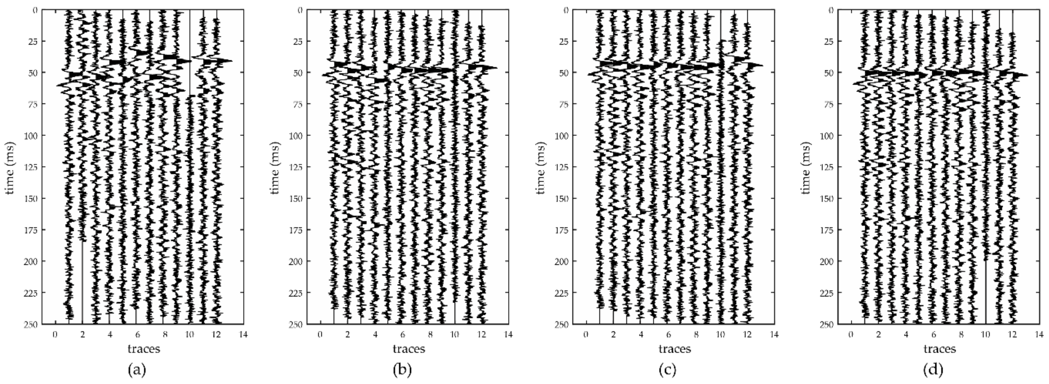
For the second noisy dataset (Figure 7b), the estimated values of the relative arrival times were obtained using the four methods (Table 7) and then used to eliminate the arrival time differences of the second dataset (Figure 11). Comparing Figure 10 with Figure 11, it can be observed that the POC (WVD) is more stable in estimating the relative arrival times when the abnormal situations exist in the monitoring record.
For the third noisy dataset (Figure 7c), the estimated value of the relative arrival times were obtained using the four methods (Table 8) and then used to eliminate the arrival time differences of the third dataset (Figure 12). Compared with other three results, the result of POC (WVD) is more robust in Figure 12.
For quantitatively evaluate the robustness of the four methods, we calculated the differences between the estimated relative arrival times obtained using the four methods in addition to the theoretical relative arrival times, and calculated the standard deviations of these differences.
σ = 1 N i = 1 N ( t estimate _ i t true _ i ) 2  
where σ denotes the standard deviation, N denotes the number of traces, t estimate denotes the estimate value of the relative arrival time, and t true denotes the true value of the relative arrival time.
Table 9 shows the standard deviations of the results (excluding the 10th trace) based on the four methods. For the interferences of noise and the code wave of the microseismic event, there are obvious errors for the estimated arrival times based on AIC. For the cross-correlation, it is hard to handle abnormal situation of the monitoring record. Due to the advantage of using the peak values of the POC functions as weighting coefficients to improve the consistency, POC (STFT), and POC (WVD) were found to have better stability in estimating the relative arrival times. By using a time window, STFT can obtain the time-frequency representation of the data. The resolution of STFT is fixed due to fixed sliding window length. Wigner-Ville distribution has the ideal time-frequency resolution [47]. For the difference of the time-frequency resolution, the estimation of the relative arrival time based on WVD is better than that based on STFT.

5. Discussion and Conclusions

In order to handle the low SNR record, real-time monitoring, and abnormal situations of monitoring equipment, we proposed a new method based on phase-only correlation to estimate the relative arrival times of microseismic events. We initially used time-frequency transform to suppress noise. Furthermore, the position of the peak value of the POC function of the time-frequency spectra was used to indicate the relative arrival times between traces. Since the peak value of the POC function can indicates the similarity between traces, we finally used the peak values as weighting coefficients to improve the consistency of the estimated relative arrival times and eliminate the effect of abnormal situations of the monitoring equipment. Beacause the peak value and the position of the peak value of the POC function are automatically obtained, the whole processing does not require manual intervention. Therefore, the proposed method can meet the requirements of real-time monitoring.
According to the synthetic data and field data employed in this study, the proposed method is valid. In particular, it was found that POC (WVD) is the most stable method when abnormal situations arise in the monitoring equipment. The advantages of the proposed method include the following. (1) Due to the time-frequency sparseness of the microseismic event, the time-frequency representation of the event record can be used to suppress random noise. The time-frequency resolution of WVD is better than that of STFT. So, POC (WVD) is more stable than POC (STFT). (2) Excluding the effect of the amplitude components, the POC function merely calculates the difference between the phase components. It is useful to process two signals with a significant energy difference. (3) The peak values of the POC can be used as weighting coefficients of linear equations to improve the consistency of the relative arrival time among the traces.

Author Contributions

Each author has contributed to the present paper. X.C. conceived the method and directed the experiments; P.W. and X.Z. performed the experiments; P.W. analyzed the data and wrote the paper.

Funding

This research was funded by the National Natural Science Foundation of China (grant number: 41604099, 41390455) and the Open Fund of Key Laboratory of Exploration Technologies for Oil and Gas Resources (Yangtze University) (grant number: K2016-01).

Conflicts of Interest

The authors declare no conflict of interest.

References

  1. Fujii, Y.; Ishijima, Y.; Deguchi, G. Prediction of coal face rockbursts and microseismicity in deep longwall coal mining. Int. J. Rock Mech. Min. Sci. 1997, 34, 85–96. [Google Scholar] [CrossRef]
  2. Ge, M. Efficient mine microseismic monitoring. Int. J. Coal Geol. 2005, 64, 44–56. [Google Scholar] [CrossRef]
  3. Daniels, J.; Waters, G.; Le Calvez, J.; Bentley, D.; Lassek, J. Contacting More of the Barnett Shale through an Integration of Real-Time Microseismic Monitoring, Petrophysics, and Hydraulic Fracture Design. In Proceedings of the SPE Annual Technical Conference and Exhibition, Anaheim, CA, USA, 11–14 November 2007. [Google Scholar] [CrossRef]
  4. Maxwell, S.C.; Rutledge, J.; Jones, R.; Fehler, M. Petroleum reservoir characterization using downhole microseismic monitoring. Geophysics 2010, 75, 129–137. [Google Scholar] [CrossRef]
  5. Tenma, N.; Yamaguchi, T.; Zyvoloski, G. The Hijiori hot dry rock test site, Japan: Evaluation and optimization of heat extraction from a two-layered reservoir. Geothermics 2008, 37, 19–52. [Google Scholar] [CrossRef]
  6. Verdon, J.P.; Kendall, J.M.; White, D.J.; Angus, D.A. Linking microseismic event observations with geomechanical models to minimise the risks of storing CO2 in geological formations. Earth Planet. Sci. Lett. 2011, 305, 143–152. [Google Scholar] [CrossRef]
  7. Wilson, M.P.; Worrall, F.; Davies, R.J.; Almond, S. Fracking: How far from faults? Geomech. Geophys. Geo-Energy Geo-Resour. 2018, 4, 193–199. [Google Scholar] [CrossRef] [Green Version]
  8. Dyskin, A.V.; Basarir, H.; Doherty, J.; Elchalakani, M.; Joldes, G.R.; Karrech, A.; Lehane, B.; Miller, K. Computational monitoring in real time: Review of methods and applications. Geomech. Geophys. Geo-Energy Geo-Resour. 2018, 4, 235–271. [Google Scholar] [CrossRef]
  9. Ge, M.; Kaiser, P.K. Interpretation of physical status of arrival picks for microseismic source location. Bull. Seismol. Soc. Am. 1990, 80, 1643–1660. [Google Scholar]
  10. Rutledge, J.T.; Phillips, W.S. Hydraulic stimulation of natural fractures as revealed by induced microearthquakes, Carthage Cotton Valley gas field, east Texas. Geophysics 2003, 68, 441–452. [Google Scholar] [CrossRef]
  11. Reyes-Montes, J.M.; Pettitt, W.; Hemmings, B.; Young, R.P. Application of Relative Location Techniques to Induced Microseismicity from Hydraulic Fracturing. In Proceedings of the SPE Annual Technical Conference and Exhibition, Society of Petroleum Engineers, New Orleans, LA, USA, 4–7 October 2009. [Google Scholar] [CrossRef]
  12. Dong, L.; Li, X. A microseismic/acoustic emission source location method using arrival times of PS waves for unknown velocity system. Int. J. Distrib. Sens. Netw. 2013, 9, 307489. [Google Scholar] [CrossRef]
  13. Akram, J.; Eaton, D.W. A review and appraisal of arrival-time picking methods for downhole microseismic data. Geophysics 2016, 81, KS71–KS91. [Google Scholar] [CrossRef]
  14. García, L.; Álvarez, I.; Benítez, C.; Titos, M.; Bueno, Á.; Mota, S.; de la Torre, Á.; Segura, J.C.; Alguacil, G.; Díaz-Moreno, A.; et al. Advances on the automatic estimation of the P. wave onset time. Ann. Geophys. 2016, 59, S0434. [Google Scholar] [CrossRef]
  15. Allen, R.V. Automatic earthquake recognition and timing from single traces. Bull. Seismol. Soc. Am. 1978, 68, 1521–1532. [Google Scholar]
  16. Zhang, R.; Zhang, L. Method for identifying micro-seismic P-arrival by time-frequency analysis using intrinsic time-scale decomposition. Acta Geophys. 2015, 63, 468–485. [Google Scholar] [CrossRef]
  17. Chen, Z.; Stewart, R. A multi-window algorithm for real-time automatic detection and picking of P-phases of microseismic events. In Proceedings of the SEG Houston 2005 Annual Meeting, Houston, TX, USA, 6–11 November 2005; pp. 1288–1291. [Google Scholar] [CrossRef]
  18. Chen, Z.; Stewart, R. Multi-window algorithm for detecting seismic first arrivals. In Proceedings of the CSEG National Convention, Calgary, AB, Canada, 18 May 2005; pp. 355–358. [Google Scholar]
  19. Song, F.; Kuleli, H.S.; Toksöz, M.N.; Ay, E.; Zhang, H. An improved method for hydrofracture-induced microseismic event detection and phase picking. Geophysics 2010, 75, A47–A52. [Google Scholar] [CrossRef]
  20. Withers, M.; Aster, R.; Young, C.; Beiriger, J.; Harris, M.; Moore, S.; Trujillo, J. A comparison of select trigger algorithms for automated global seismic phase and event detection. Bull. Seismol. Soc. Am. 1998, 88, 95–106. [Google Scholar] [CrossRef]
  21. Lee, M.; Byun, J.; Kim, D.; Choi, J.; Kim, M. Improved modified energy ratio method using a multi-window approach for accurate arrival picking. J. Appl. Geophys. 2017, 139, 117–130. [Google Scholar] [CrossRef]
  22. Sedlak, P.; Hirose, Y.; Enoki, M.; Sikula, J. Arrival time detection in thin multilayer plates on the basis of the Akaike information criterion. J. Acoust. Emiss. 2008, 26, 182–188. [Google Scholar]
  23. St-Onge, A. Akaike information criterion applied to detecting first arrival times on microseismic data. In Proceedings of the SEG Annual Meeting, Society of Exploration Geophysicists, San Antonio, TX, USA, 18–23 September 2011. [Google Scholar] [CrossRef]
  24. Tselentis, G.A.; Martakis, N.; Paraskevopoulos, P.; Lois, A.; Sokos, E. Strategy for automated analysis of passive microseismic data based on S.-transform, Otsu’s thresholding, and higher order statistics. Geophysics 2012, 77, KS43–KS54. [Google Scholar] [CrossRef]
  25. Bogiatzis, P.; Ishii, M. Continuous wavelet decomposition algorithms for automatic detection of compressional and shear-wave arrival times. Bull. Seismol. Soc. Am. 2015, 105, 1628–1641. [Google Scholar] [CrossRef]
  26. Mousavi, S.M.; Langston, C.A.; Horton, S.P. Automatic microseismic denoising and onset detection using the synchrosqueezed continuous wavelet transform. Geophysics 2016, 81, V341–V355. [Google Scholar] [CrossRef]
  27. Shang, X.; Li, X.; Morales-Esteban, A.; Dong, L. Enhancing micro-seismic P-phase arrival picking: EMD-cosine function-based denoising with an application to the AIC picker. J. Appl. Geophys. 2018, 150, 325–337. [Google Scholar] [CrossRef]
  28. Moriya, H.; Niitsuma, H. Precise detection of a P-wave in low S/N signal by using time-frequency representations of a triaxial hodogram. Geophysics 1996, 61, 1453–1466. [Google Scholar] [CrossRef]
  29. Murat, M.E.; Rudman, A.J. Automated first arrival picking: A neural network approach. Geophys. Prospect. 1992, 40, 587–604. [Google Scholar] [CrossRef]
  30. Gou, X.; Li, Z.; Qin, N.; Jin, W. Adaptive picking of microseismic event arrival using a power spectrum envelope. Comput. Geosci. 2011, 37, 158–164. [Google Scholar] [CrossRef]
  31. Mousa, W.A.; Al-Shuhail, A.A.; Al-Lehyani, A. A new technique for first-arrival picking of refracted seismic data based on digital image segmentation. Geophysics 2011, 76, V79–V89. [Google Scholar] [CrossRef]
  32. Chen, Y. Automatic microseismic event picking via unsupervised machine learning. Geophys. J. Int. 2017, 212, 88–102. [Google Scholar] [CrossRef]
  33. Ross, Z.E.; Meier, M.A.; Hauksson, E. P-wave arrival picking and first-motion polarity determination with deep learning. J. Geophys. Res. Solid Earth 2018, 123, 5120–5129. [Google Scholar] [CrossRef]
  34. Zhang, H.; Thurber, C.; Rowe, C. Automatic p-wave arrival detection and picking with multiscale wavelet analysis for single-component recordings. Bull. Seismol. Soc. Am. 2003, 93, 1904–1912. [Google Scholar] [CrossRef]
  35. Saragiotis, C.; Alkhalifah, T.; Fomel, S. Automatic traveltime picking using local time-frequency maps. Geophysics 2013, 78, T53–T58. [Google Scholar] [CrossRef]
  36. Akram, J.; Eaton, D.; Onge, A.S. Automatic event-detection and time-picking algorithms for downhole microseismic data processing. In Proceedings of the EAGE Passive Seismic Workshop, Amsterdam, The Netherlands, 17–20 March 2013. [Google Scholar] [CrossRef]
  37. Li, X.; Shang, X.; Morales-Esteban, A.; Wang, Z. Identifying P phase arrival of weak events: The Akaike Information Criterion picking application based on the Empirical Mode Decomposition. Comput. Geosci. 2017, 100, 57–66. [Google Scholar] [CrossRef]
  38. Zimmer, U. Microseismic design studies. Geophysics 2011, 76, WC17–WC25. [Google Scholar] [CrossRef]
  39. Tan, Y.; He, C. Improved methods for detection and arrival picking of microseismic events with low signal-to-noise ratios. Geophysics 2016, 81, KS93–KS111. [Google Scholar] [CrossRef]
  40. VanDecar, J.C.; Crosson, R.S. Determination of teleseismic relative phase arrival times using multi-channel cross-correlation and least squares. Bull. Seismol. Soc. Am. 1990, 80, 150–169. [Google Scholar]
  41. Eisner, L.; Abbott, D.; Barker, W.B.; Lakings, J.; Thornton, M.P.; Microseismic Inc. Noise suppression for detection and location of microseismic events using a matched filter. In Proceedings of the SEG Annual Meeting. Society of Exploration Geophysicists, Las Vegas, NV, USA, 9–14 November 2008. [Google Scholar] [CrossRef]
  42. Kummerow, J. Using the value of the crosscorrelation coefficient to locate microseismic events. Geophysics 2010, 75, MA47–MA52. [Google Scholar] [CrossRef]
  43. Ito, K.; Nakajima, H.; Kobayashi, K.; Aoki, T.; Higuchi, T. A fingerprint matching algorithm using phase-only correlation. IEICE Trans. Fundam. Electron. Commun. Comput. Sci. 2004, 87, 682–691. [Google Scholar]
  44. Moriya, H. Phase-only correlation of time-varying spectral representations of microseismic data for identification of similar seismic events. Geophysics 2011, 76, WC37–WC45. [Google Scholar] [CrossRef]
  45. Wang, S.L.; Fang, Y.; Fang, J. Diagnostic prediction of complex diseases using phase-only correlation based on virtual sample template. BMC Bioinform. 2013, 14, S11. [Google Scholar] [CrossRef] [PubMed]
  46. Wu, S.; Wang, Y.; Zhan, Y.; Chang, X. Automatic microseismic event detection by band-limited phase-only correlation. Phys. Earth Planet. Inter. 2016, 261, 3–16. [Google Scholar] [CrossRef]
  47. Zhang, L.; Wang, Y.; Chang, X. Wigner distribution based phase-only correlation. J. Appl. Geophys. 2015, 123, 277–282. [Google Scholar] [CrossRef]
  48. Cohen, L. Generalized phase-space distribution functions. J. Math. Phys. 1966, 7, 781–786. [Google Scholar] [CrossRef]
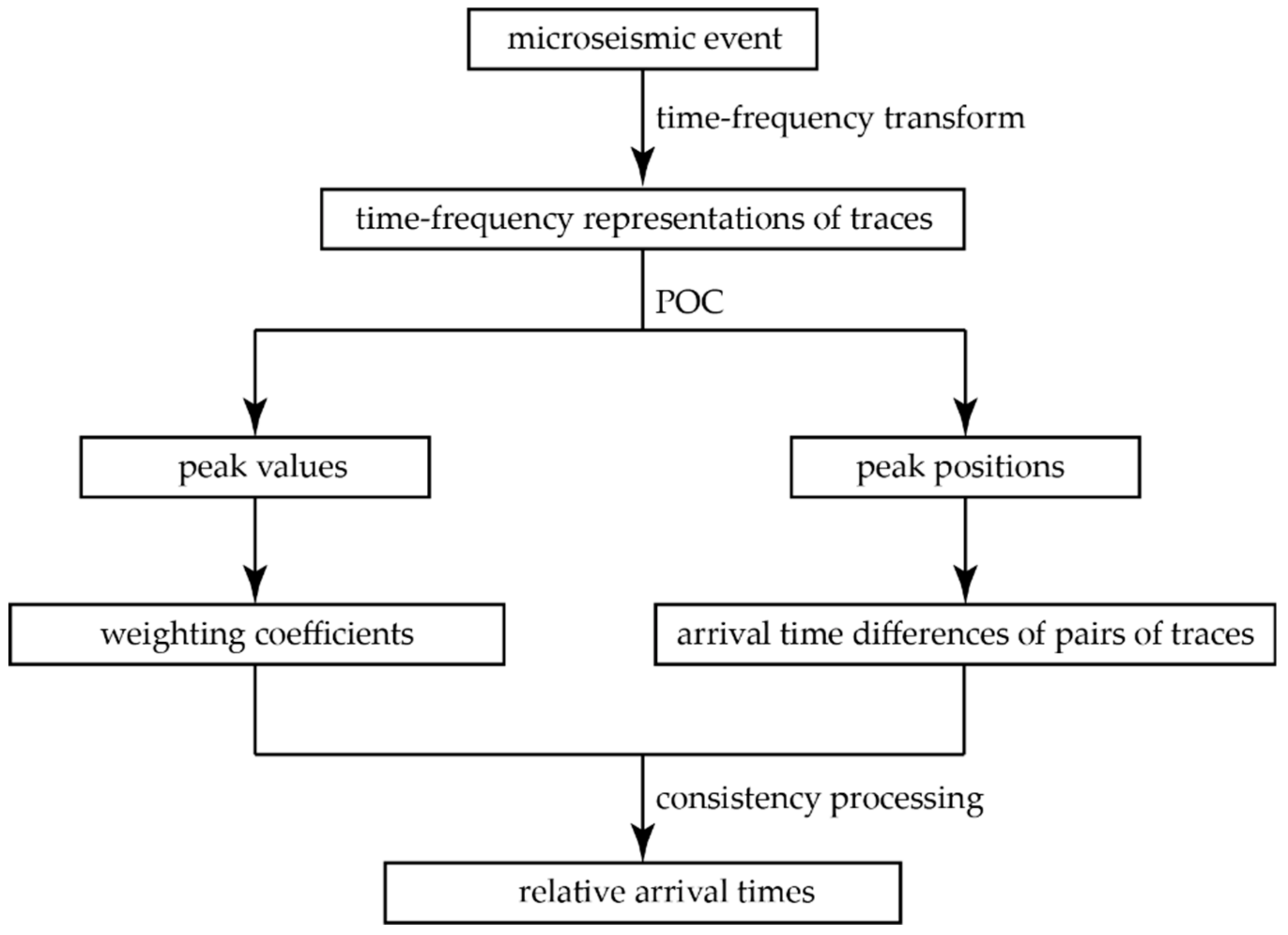
Figure 1. The flowchart of the proposed method for estimating relative arrival times. The procedure of this method starts with time-frequency transform, followed by phase-only correlation (POC) and consistency processing.
Energies 11 02527 g001
Figure 2. The waveforms of the synthetic data.
Energies 11 02527 g002
Figure 3. The time-frequency representations of two traces: (a) the result of time-frequency transform of Trace 1; (b) the result of time-frequency transform of Trace 4.
Energies 11 02527 g003
Figure 4. The POC of the first trace and the fourth trace. The peak value of the POC is located in −45 of the time lag axis.
Energies 11 02527 g004
Figure 5. The waveforms of the microseismic event. (a) the P-wave and S-wave waveforms; (b) the P-wave record, which is a segment of the microseismic event from 325.25 ms to 575 ms.
Energies 11 02527 g005
Figure 6. Using the calculation results of relative arrival times as the adjusting value to eliminate the arrival time difference among traces. (ad) Akaike Information Criterion (AIC), cross-correlation, phase-only correlation (short time Fourier transform) (POC (STFT)), and phase-only correlation (Wigner-Ville distribution) (POC (WVD)) were used to estimate the relative arrival times of the P-wave record.
Energies 11 02527 g006
Figure 7. The 10th trace of the P-wave record is replaced by background noise, and the P-wave record is aminated by different levels of Gaussian white noises. (a) The signal-to-noise ratio of the first noisy data is 5 dB; (b) the signal-to-noise ratio of the second noisy data is 0 dB; (c) the signal-to-noise ratio of the third noisy data is −2 dB.
Energies 11 02527 g007
Figure 8. The POC function between the first trace and the 10th trace.
Energies 11 02527 g008
Figure 9. The POC function between the first trace and the 12th trace.
Energies 11 02527 g009
Figure 10. Using estimation values of the relative arrival times to eliminate the arrival time difference among the traces of the first noisy dataset. (a) The result based on AIC; (b) the result based on cross-correlation; (c) the result based on POC (STFT); (d) the result based on POC (WVD).
Energies 11 02527 g010
Figure 11. Using estimation values of the relative arrival times to eliminate the arrival time difference among the traces of the second noisy data. (a) The result based on AIC; (b) the result based on cross-correlation; (c) the result based on POC (STFT); (d) the result based on POC (WVD).
Energies 11 02527 g011
Figure 12. Using estimation values of the relative arrival times to eliminate the arrival time difference among the traces of the third noisy data. (a) The result based on AIC; (b) the result based on cross-correlation; (c) the result based on POC (STFT); and (d) the result based on POC (WVD).
Energies 11 02527 g012
Table 1. Symbols present in this article.
SymbolDefinition
f ( n , w ) the time-frequency representation of one trace
F ( k 1 , k 2 ) the two-dimensional (2D) discrete Fourier transform of f ( n , w )
R ^ F G ( k 1 , k 2 ) the cross-phase spectrum between F ( k 1 , k 2 ) and F ( k 1 , k 2 )
A F ( k 1 , k 2 ) the amplitude component of F ( k 1 , k 2 )
e j θ F ( k 1 , k 2 ) the phase component of F ( k 1 , k 2 )
r ^ f g ( n , ω ) the phase-only correlation (POC) function between f ( n , w ) and g ( n , w )
r f g the peak value of the POC function r ^ f g ( n , ω )
Δ t i j the relative arrival time between the ith and jth traces
Table 2. The arrival time differences of all the pairs of traces.
Trace NumberTrace 1Trace 2Trace 3
Trace 2−15 ms
Trace 3−30 ms−15 ms
Trace 4−45 ms−30.5 ms−15 ms
Table 3. The comparison of the theoretical values and the estimated values of the relative arrival times.
Relative Arrival TimesTrace 1Trace 2Trace 3Trace 4
Theoretical values015 ms30 ms45 ms
Estimated values015 ms30.1 ms45.4 ms
Error000.1 ms0.4 ms
Table 4. The relative arrival times of the microseismic event using the four methods.
Methods1st2nd3rd4th5th6th7th8th9th10th11th12th
AIC0−1.75−4−5−6.75−8.5−10.5−11.75−13.5−15−19−20.5
Cross-correlation0−2.18−3.23−5.23−6.58−8.6−10.3−11.43−13.85−15.03−19.15−20.98
POC (STFT)0−2−3.7−5.45−7.2−8.95−11−12.6−14.1−15.95−19.25−21.05
POC (WVD)0−1.75−2.85−4.58−6.58−8.23−9.85−11.3−13.98−14.83−18.53−20.28
Average0−1.93−3.45−5.07−6.78−8.57−10.41−11.78−13.86−15.2−18.98−20.7
Table 5. The peak values (×10−4) of the phase-only correlation (Wigner-Ville distribution) (POC (WVD)) for all pairs of traces.
Trace Number1st2nd3rd4th5th6th7th8th9th10th11th
2nd4.8
3rd5.24.5
4th5.14.35.1
5th4.83.65.44.9
6th5.14.25.55.35.6
7th5.03.65.65.15.65.5
8th4.73.84.75.04.65.04.7
9th5.35.05.14.94.75.04.74.5
10th1.11.21.11.01.01.01.11.01.1
11th4.13.04.84.85.05.04.63.54.31.0
12th4.33.35.05.15.35.35.24.34.40.95.4
Table 6. The estimated values of the relative arrival times of the first noisy dataset (signal-to-noise ratio (SNR) = 5 dB).
Methods1st2nd3rd4th5th6th7th8th9th10th11th12th
AIC0−37.5−20.7540−4.25−5.75−24.25−7−15.75−82.5−24.5−21.75
Cross-correlation0−5.83−12.05−13.98−3.2−17.38−19−14.88−20.638.3−19.2−21.7
POC (STFT)0−1.98−3.63−5.15−7.33−8.7−10.65−12.35−13.8859.33−15.65−20.68
POC (WVD)0−1.3−2.1−3.6−6.25−8.45−8.8−11.15−13.7347.48−18.05−18.83
Table 7. The estimated values of the relative arrival times of the second noisy dataset (SNR = 0 dB).
Methods1st2nd3rd4th5th6th7th8th9th10th11th12th
AIC062.25−5.254.75−10.758.5−12.52.5−3.25−71.5−9−10.25
Cross-correlation0−7.45−6.25−18.2−8.83−13.63−15.43−16.25−18.755.4−21.2−24.2
POC (STFT)0−1.68−5.65−7.63−7.5−10.28−13.18−13.18−14.53−36.4−15.58−22.38
POC (WVD)0−2.58−3.63−5.63−8.65−8.9−10.35−10.23−14.3545.8−19.23−22.78
Table 8. The estimated values of the relative arrival times of the third noisy dataset (SNR = −2 dB).
Methods1st2nd3rd4th5th6th7th8th9th10th11th12th
AIC053.75−8.25−5−19.257.50.25−2−14167−15−31.75
Cross-correlation0−1.812.29−2.5-−4.6−5.6−5.75−11.67−10.75−0.33−24.17−16.6
POC (STFT)0−3.66−9.22−4.7−11.9−10.84−12.45−14.73−16.78−17.96−21.18−19.68
POC (WVD)0−2.63−2.96−5.08−7.46−6.88−7.06−9.11−12.89.48−16.74−19.47
Table 9. The standard deviations of the relative arrival time of the microseismic event under different signal-to-noise ratios, while one abnormal trace exists in the record.
SNRAICCross-CorrelationPOC (STFT)POC (WVD)
Without noise0.220.200.250.22
5 dB18.644.21.030.62
0 dB17.973.191.660.91
−2 dB17.757.062.011.29