5.1. CPIM of the Each Component in the Cyber-Physical Substation
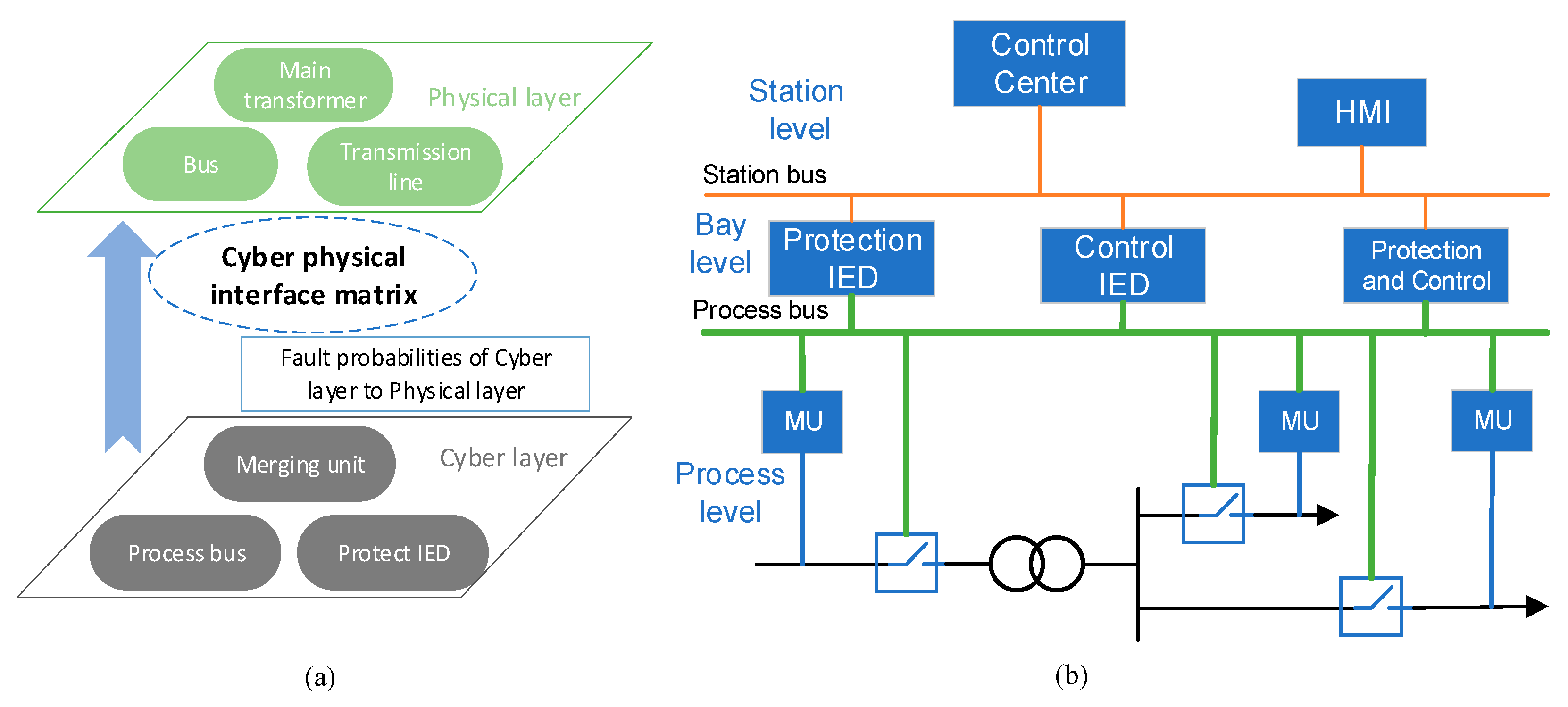
A simplified model of a typical the substation based on the IEC 61850 standard in China is shown in
Figure 4, which is a 220/121/38.5 kV step-down substation. The annual average load of both load-point-1 and load-point-2 are 100 MW. The details for the primary devices of the substation are shown in
Table 3.
In
Figure 4, there are 11 breakers, denoted as 1, 2, 3…;
A and
J stand for the transmission lines; C, D, E are main transformers; MU is the merging unit, and the number of MUs is 8, denoted as by MU1, MU2 …; B, F, G, H, I are the buses. According to (1), the shape of the CPM of
Figure 4 is shown as (11). In (11), there are 10 physical devices, denoted as
A,
B,…
J, thus the row number is
m = 10, each row vector means the CPIM of a physical device. For example, the CPIM of the physical device A is denoted as
, where
a is the number of cascading scenarios of A; similarly, the CPIM of the physical device B is denoted as
, where
b is the number of cascading scenarios of B; the
CPIM of the physical device J is denoted as
, where
j is the number of cascading scenarios of J; Thus, the number of columns of
CPM is
a +
b… +
j. The
CPIM of each physical device shows from
Table 4,
Table 5,
Table 6,
Table 7,
Table 8,
Table 9,
Table 10,
Table 11,
Table 12 and
Table 13.
Based on the CPIM method in
Section 3, considering a failure clearing at line A, the CPIM
A are shown in
Table 4. In this case, there are three kinds of cascading chains within the substation. scenario 1: If all the related cyber devices are working functionally, the breaker can obtain the failure information, and then locate and clear the failure. The failure scope would be limited within A, which is the low-impact case mentioned in
Section 2. In
Table 4, the results show that when line fault clearance occurs at A, more than 99% failures are limited to within A. However, in extremely few cases, the failure scope would extend to the entire system, due to the dysfunctional working of the process bus connected to A, which is the wide-impact case mentioned in
Section 2. In
Table 4, the probability of this occurrence is the smallest. With a small probability of 0.3%, among breaker 1, merging unit 1, and protection IED of A, more than one cyber device may be malfunctioning; thus, it leads to breaker 1 failure and then resulting in the failure of B. At this time, breakers 2, 3, and 4 can work functionally, thus limiting the failure scope to within A and B, which is the local-impact case mentioned in
Section 2. Thus, based on
Table 4, the number of cascading scenario is 3, and the CPIM
A = [0.996957511, 0.003009105, 0.000033384]
1×3; it satisfied sum{CPIM
A} = 1. Using the same method, the CPIM of the line fault clearance at transmission line J can be obtained as the CPIM
J = [0.996957511, 0.003009105, 0.000033384]
1×3, results showing as
Table 5.
Table 6 shows a similar analysis in the case of a failure clearing at bus B. In this case, consider all cyber devices are connected to B, such as merging units 1, 2, 3, and 4; breakers 1, 2, 3, and 4; and the process bus. The three kinds of cascading chains could occur within the substation: Low-impact, wide-impact, and local impart. In
Table 6, more than 99% of failures are limited to within B, due to all the related cyber devices functioning properly. However, having a smaller probability 0.3%, the failure scope would extend to entitle system, due to the dysfunctional working of the process bus. According to the different sizes of failure scopes caused by different related cyber devices, four kinds of local-impact may occur with minimal probability.
In
Table 6, there are four types of local-impacts, denoted as local-impact 1, 2, 3, 4, and the number of cascading scenarios is 17. Local-impact 1: If one of the merging units or related breakers malfunctions, the failure effect scope would be limited to B and one of its connecting physical devices. The number of cascading scenarios belongs to local-impact 1 is 4. For example, either merging unit 2 or the breaker 2 is dysfunctional, while the others are functional, then the effect scope is limited to within B and C. Local-impact 2: If two of merging units or related breakers are dysfunctional, this case would limit the failure effect scope to B and two of its connecting physical devices. The number of cascading scenarios belongs to local-impact 2 is 6. For example, the effect scope ABE might result from the failure at breakers 1 and 4, and merging units 1 and 4. Similarly, If three (four) of the merging units or related breakers malfunction, this would limit the failure effect scope to B and three (four) of its connecting physical devices. The number of cascading scenarios belongs to local-impact 3 and local-impact 4 are 4 and 1.
Thus, based on
Table 6, the number of cascading scenarios is 17, and the CPIM
B = [0.996911991, 0.000015173, 0.000015173, 0.000015173, 0.000015173, 1.38564396
−10, 1.38564396
−10, 1.38564396
−10, 1.38564396
−10, 1.38564396
−10, 1.38564396
−10, 3.51492326
−15, 3.51492326
−15, 3.51492326
−15, 3.51492326
−15, 1.82105929
−5, 0.003009105]
1×17, it satisfied sum{CPIM
B} = 1. Using the same method, the CPIM of the line fault clearance at bus F, H, G, I can be obtained as follows: The CPIM
F = [0.996957511, 0.003009105, 0.000033384]
1×3, the CPIM
G = [0.996957511, 0.003009105, 0.000033384]
1×3, the CPIM
H = [0.996957511, 0.003009105, 0.000033384]
1×3, CPIM
I = [0.996911991, 0.000015173, 0.000015173, 0.000015173, 0.000015173, 1.38564396
−10, 1.38564396
−10, 1.38564396
−10, 1.38564396
−10, 1.38564396
−10, 1.38564396
−10, 3.51492326
−15, 3.51492326
−15, 3.51492326
−15, 3.51492326
−15, 1.82105929
−5, 0.003009105]
1×17, all results showing from
Table 7,
Table 8,
Table 9 and
Table 10.
Using the same analysis method,
Table 11 shows the results under failure clearing at transformer C. The results summary is similar to
Table 6: (1) More than 99% failures are low-impact, limited to within C; (2) within a smaller probability of 0.3%, the failure scope extends to the entire system, due to the dysfunctional working of the process bus, being a wide-impact; and (3) local-impact are classified according to the failure number of the related cyber device, of which the occurrence has low probability. Thus, based on
Table 11, the number of cascading scenarios is 9, and the CPIM
C = [0.996927164, 1.51734070
−5, 1.51734070
−5, 1.51734070
−5, 2.30941925
−10, 2.30941925
−10, 2.30941925
−10, 1.82100387
−5, 0.003009105]
1×9, satisfied sum{CPIM
C} = 1.
Using the same method, the CPIM of the line fault clearance at transformer D, E can be obtained as follows: CPIM
D = [0.996927164, 1.51734070
−5, 1.51734070
−5, 1.51734070
−5, 2.30941925
−10, 2.30941925
−10, 2.30941925
−10, 1.82100387
−5, 0.003009105]
1×9, CPIM
E = [0.996927164, 1.51734070
−5, 1.51734070
−5, 1.51734070
−5, 2.30941925
−10, 2.30941925
−10, 2.30941925
−10, 1.82100387
−5, 0.003009105]
1×9, all results showing from
Table 12 and
Table 13.


