Article

A Micro Swing Rotor Engine and the Preliminary Study of Its Thermodynamic Characteristics

College of Energy and Power Engineering, Nanjing University of Aeronautics and Astronautics, Nanjing 210016, China
*
Author to whom correspondence should be addressed.
Energies 2018, 11(10), 2684; https://doi.org/10.3390/en11102684
Submission received: 3 September 2018 / Revised: 27 September 2018 / Accepted: 29 September 2018 / Published: 9 October 2018

Abstract

:
The rapid progress in microelectromechanical system technology has facilitated great developments in micro heat engines, however, defects in these engines still need to be overcome. Thus, a novel four-stroke micro swing rotor engine (MSRE) that features the advantages of Wankel engine and the micro swing engine is proposed in this study. Kinematic and thermodynamic analyses of the MSRE were performed, and a preliminary experimental research was conducted. In the MSRE, the driver assembly was used to dominate the movements of the two rotors. By the design guideline adaptable to the engine operation principle, the volume of each chamber will vary in a sine-like waveform, which was validated by kinematic analyses. Then, a prototype in mesoscale was designed and fabricated. In consideration of the leakage effect, the thermodynamic characteristics of this engine were numerically investigated. Results indicate that the engine thermodynamic processes were seriously affected by leakage flow, especially when working at low frequencies. Gap height and operation frequency were the two dominant factors that affected engine performance. Under a certain gap height, the MSRE had to work at a specific frequency range and the corresponding optical values exist for engine efficiency and power. With a 20 μm height, the MSRE reached the maximum efficiency of 23.62% at 55 Hz and the maximum power of 3442 W at 95 Hz. Feasibility of the engine was further verified by an experimental test on the operation characteristics, including the cold state test with pressured air blow and the combustion test for engine operation at thermal state. This research lays a good foundation for future development of MSRE, which is of great practical significance for the progress in micro power systems.

1. Introduction

Currently, microelectromechanical systems (MEMS) are widely applied to fabricate devices in micro and mesoscales, such as sensors, actuators, micro-airplanes, micro aerial vehicle (MAV), and micro-robots. However, battery systems are the main power sources for these applications. Unfortunately, even the most advanced lithium-ion batteries only have an energy density of approximately 1.2 kJ/g [1]. This value is so poor that increasing fractions of the mass and volume of the entire MEMS-based devices are being occupied by batteries, which have a short durable time and a limited number of rechargeable cycles. The lack of compact, efficient, instantly rechargeable power supply devices with high-specific energy (light weight, long duration) and power greatly limits the development of micro-systems for various applications [2,3]. As sustainable resources, the condensed HC fuels contain much higher energy density (typically 45 MJ/kg), and the internal combustion micro engine systems for power generation are far superior to battery-motor electrical systems in the 1–100 W range, even with thermal efficiencies as low as 4% [4,5,6]. Therefore, combustion-based micro heat engines have become the most promising alternative as commercial power supply for micro devices to conventional battery systems. Micro engines have attracted increasing attention nowadays because of their potential applications in power generation. During the last decades, great efforts have been exerted to promote the development in this field and different types of miniaturized engines have been manufactured, including micro gas turbine, micro free-piston engine, micro rotary (Wankel) engine, micro swing engine, etc. A series of theoretical and experimental works on this topic are available in the literature.
The MIT Gas Turbine Laboratory has developed several advanced MEMS-based micro gas turbines for power generation and discussed relevant issues [7,8]. Composed of silicon-carbide material, the first concept heat engine was designed to produce 10–20 W power; the working volume was about 300 mm3 [7]. Since then, advanced air bearing has been improved, allowing turbines to work at a high rotation velocity. In cooperation with the IHI Corporation, a research group at Tohoku University designed a rotor working at 770,000 rpm in a micro high-speed bearing test rig [9]. Later, a 100 W class micro-scale gas turbine with a centrifugal impeller of 10 mm diameter and a rotor that rotates at 870,000 rpm was experimentally investigated [10]. When the turbine inlet temperature was 1050 °C, the compressor was kept below 170 °C. Subsequently, they demonstrated the world’s smallest class gas turbine engine that established the Brayton cycle [11], indicating its promising applications for mobile robots, personal vehicles, etc. With further progress in gas bearings [12], a MEMS-based turbocharger was designed, fabricated, and tested [13], to produce a micro-fabricated gas turbine engine for portable power applications. This turbine produced approximately 5 W of power. A liquid-fueled micro engine that burns JP8 fuel is proved to be an attractive portable power source [14], because the designed micro-combustor can increase thermal efficiency. Nowadays, the research on micro gas turbine is focused on the components.
Miniaturization of the rotary Wankel engine was first conducted by a combustion laboratory at UC Berkeley. Several liquid hydrocarbon fueled rotary engines in different sizes were designed [15]. The output of a mesoscale rotary engine was about 30 W with a 12.9 mm-diameter rotor [16]. In the first stage work of a research project launched by the University of Birmingham, an advanced UC-lithography process was developed, and a CO2 micro Wankel engine was successfully fabricated [17]. Sprague et al. [18] developed and characterized four small-scale rotary engines for portable applications in the output range of 10–200 W. The highest performing engine produced 33 W of power with an efficiency of 3.9%; the combustion chamber had a volume of 1.5 cm3. Zhejiang University in China designed and fabricated a series of small-scale rotary engines by using electro discharge machining [19]. Their M2.4 rotary engine, with a swept displacement of 2600 mm3, showed a steady 150 W net power output at 15,000 rpm. They pointed out that micro combustion and seal are two of the most prominent questions for small-scale rotary engines. Considering that the scaling down of rotary Wankel engines is limited by various factors, Wang et al. [20] developed a phenomenological model to investigate the effects of engine speed, compression ratio, blow-by, and heat transfer, and thus, provided guidelines for the preliminary design of rotary engines. In fact, various rotary engines have been designed, and the Wankel engine is just one type of them. The Yo-Mobile Engine developed in Russia has been reportedly applied in hybrid cars. Pan et al. [21,22,23] have designed several twin-rotor piston engines. However, the mechanism was modified to be more and more complicated, rendering it unfit for miniaturization.
To avoid the serious sealing problem in rotary engines, the Honeywell center first developed a mesoscale free-piston knock engine using homogeneous charge compression ignition (HCCI) of hydrocarbon fuels [24,25]. A series of single shot combustion experiments on the rapid compression expansion machine were carried out to investigate the free piston motion at Minnesota University [26,27]. Experiments showed that HCCI combustion could be successful even in spaces with 3 mm diameter and 0.3 mm length. Although the HCCI inter-combustion engines have developed rapidly, the smaller version design has many restrictions. Therefore, I. Sher et al. [2,28] proposed a phenomenological model to consider the relevant processes in the HCCI engine. The influences of friction losses and charge leakage on engine performance were studied and inter-relationships between them were postulated. An approximated analytical solution was proposed to yield the lower possible limits of scaling-down HCCI cycle engines. Jin Bai et al. [29] have studied the methane HCCI in a micro free-piston engine. A formula for the critical initial kinetic energy, especially affected by leakage, was proposed to guide the design of micro free-piston power devices. The simulation results from their team [30] revealed that catalytic combustion facilitates energy conversion efficiency and extends the ignition limit of methane-air mixture obviously, which can be attributed to the existence of a catalytic wall.
At the University of Michigan, Mijit et al. [31,32] proposed the micro internal combustion swing engine (MICSE), a rotationally oscillating free-piston engine. In this engine, a center swing that moves back and forth divides the base cavity into four chambers. Thus, a four-stroke MICSE that could produce 20 W of electrical power was designed. A numerical investigation was conducted by Gu et al. [33] to examine premixed the flame propagation in a generic mesoscale combustion chamber for various injection and ignition configurations. Results indicated that the mean flow and turbulence must be matched to the combustion chamber geometry to minimize the overall combustion time. Based on the main working principle of the MICSE, Zhang et al. [34,35] developed a novel two-stroke cycle micro free-piston swing engine, with a simplified structure and control system. The feasibility was validated by the successful realization and operation of the theoretical prototype; some performance analyses were executed numerically. A constant-speed model for the four-stroke MICSE has been developed to control the engine accurately [36]. However, irreversible losses in the MICSE are still serious, especially the leakage effect. Zhou et al. [37] investigated the leakage mechanism in detail and found that the performance reduction for the mesoscale swing engine was small for gap heights within 6 μm but was large for gap heights over 10 μm. Since a large amount of energy is wasted through hot exhaust, the recuperation technology suitable for MICSE is indispensable to elevate the engine efficiency. Therefore, Xia et al. [38] have proposed a hybrid thermodynamic cycle with heat recovery process, which was validated by numerical simulation.
At present, three phenomenological models have been developed to describe the engine working process; that is, the zero, quasi, and multi-dimensional combustion model. Compared to the other two models, the zero-dimensional combustion model is able to largely reduce the time and calculation cost, and meanwhile, offer creditable results [31]. Because the spatial distribution of physical parameters is not considered in this model, only several simple boundary and initial conditions are required. Consequently, it has been widely adopted to obtain the thermodynamic characteristics of micro engines.
Given close analysis on the aforementioned literature, the high working temperature and rotation speeds have seriously constrained the application of micro gas turbines. Sealing and friction problems must be overcome to promote the application of micro rotary engines. The micro free-piston engine must operate at kilohertz frequencies under short ignition delay times to achieve reliable auto-ignition of the fuel. Although the free swing-arm in the MICSE moves simply, in a rotating motion with less vibration, the engine cannot run stably in constant compress ratio because of irreversible losses. Referring to the control method of constant compress ratio in a reciprocating piston engine, this study proposed a novel micro swing rotor engine (MSRE), which features the advantage for Wankel engine, i.e., great ratio of power to volume, and that for MICSE, i.e., good cavity structure without valves favorable to scaling down. The operation principle and structural components of this creative power device are thoroughly elaborated. Motion analysis is conducted through the MATLAB program along with the motion module of UG to validate the design method for a mesoscale prototype. In the following research, a thermodynamic investigation of the engine that works in steady state was performed. Thermal performance curves are discussed for the MSRE under different compress ratios. The leakage effect and rotating frequency considerably influence the overall thermal characteristics, and the mechanisms were observed. Hence, the results of this study are used as a basis for the performance estimation and the guideline of engine design. Lastly, an experimental platform for the MSRE was designed and established. Preliminary test of the engine performance was implemented to verify the feasibility of this micro heat engine. This research will lay a good theory and experimental foundation for further development of MSRE, which is of great practical significance for the progress in micro energy power systems.

2. Operation Principle and Mechanical Design of the Micro Swing Rotor Engine

2.1. Working Principle for this Novel Engine

The MSRE is a dual rotor piston engine. As shown in Figure 1, this engine is composed of a cylinder assembly and a driver assembly. In the cylinder base, two rotors, which are individually fixed on the two swing links in the driver assembly and powered by the fuel charged through the inlet, rotate in the same direction. For the driver components, the principal function is to constrain the rotor motion, whose spindle is the main output link of the engine. Since each rotor holds two opposite blades (arms), the base structure is divided into four independent closed chambers by two rotors, which are coaxially installed in the MSRE. Rotations of the two rotors are controlled by a specially designed external driving mechanism, so that the two rotors can move in differential velocities at any time for one period once the output spindle rotates at one certain speed. Therefore, the volume of each chamber varies accordingly. Similar to the thermodynamic process in the conventional four-stroke internal combustion (IC) engine, the four chambers work in four strokes but are in a distinct four-stroke process at any time. Vice versa, once the fuel is combusted and then expands, the two rotors are driven to output power and the MSRE will work continuously. The internal energy is thus converted into mechanical energy successfully. Take one chamber (Chamber A) for instance: the operation process of MSRE is demonstrated in Figure 2 for one rotation period of the spindle.

2.2. Design of the Driving Mechanism and Kinematic Analysis

The driving mechanism (i.e., the driver assembly) of the MSRE was composed of a planetary gear mechanism and two crank-rocker mechanisms, which were coaxially linked by two groups of planet gear and crank and share the same brackets (Figure 3). That is, the planet carrier of the planetary gear mechanism was the support bar of the crank-rocker mechanisms at the same time. More importantly, it functioned as the output spindle for the driver assembly and even for the engine. The two four-bar linkages were installed on the same frame in the opposite direction with a phase divergence of π, and each rocker was fixedly connected to one rotor. Thus, once the bracket rotates at a certain speed, one pursue motion between the two rotors is realized. Given that the sun gear was fixed on the engine body frame stationary, a one-degree-of-freedom driving mechanism was established. In cooperation with the planetary gear train, the rotors were constrained to rotate at a speed that fluctuates periodically, thereby resulting in the relative motion that made the included angle between two arms (chamber volume) vary periodically. The specially designed driving mechanism was determined by the bar lengths of the four-bar linkages and the transmission ratio of planetary gear train, which were calculated through a series of reasonable approaches, including the closed vector method and the center of speed method. Lastly, the operation principle of MSRE was satisfied.
In view of the structure design of the complete engine, the requirements of the compression ratio ε and the arm thickness-angle β in the cylinder assembly had to be met. The relationship among the two factors and the bar-lengths are expressed as
cos l ( l 1 2 + l 4 2 ( l 2 + l 3 ) 2 2 l 1 l 4 ) cos 1 ( l 1 2 + l 4 2 ( l 2 ) 2 2 l 1 l 4 ) = π ( 180 2 β ) 360 ε 1 ε + 1  
where l 1 , l 2 , l 3 , and l 4 represent the length of planet carrier, crank, connecting rod, and rocker, respectively.
According to the design guideline of the aforementioned driving mechanism, Table 1 shows one group structure parameters of this engine, in which the compression ratio of MSRE is 6. Since this study is just in the first stage of our research, the principle prototype was designed in mesoscale for convenience.
In accordance with the parameters in Table 1, a 3D modeling of the engine was established in UG software and the motion analysis has been investigated. Results from the MATLAB program agreed with the motion simulation of three-dimensional modeling conducted through UG. When the spindle rotated at a frequency of 100 Hz, the angular velocity curve of each rotor and the volume angle of one chamber could be obtained, as shown in Figure 4 and Figure 5, respectively, for one quarter period. Figure 4 shows that the rotor velocity was always greater than zero. Unlike the conventional IC engines, no reciprocating piston motion existed in the MSRE, resulting in a lower impact load. In Figure 5, the included angle between two neighboring arms varied in a sine-like waveform from the minimum value of 22.85° to the maximum angle of 137.1°, which was consistent with the designed compression ratio and met the design requirements well.

3. Thermodynamic Characteristics of the Micro Swing Rotor Engine

3.1. Thermodynamic Model for the MSRE in Steady Operation State and the Solution Method

Without regard for the details of the physical-chemical process in combustion and the inhomogeneous distribution of the working medium in space field [39,40], the single-dimensional combustion model was adopted to research the thermodynamic characteristics of the MSRE. Based on the fundamental thermodynamic processes in each chamber, differential equations are given to present the working processes for each stroke, and the time-variation process of each thermodynamic parameter is numerically solved.

3.1.1. Establishment of the Thermodynamic Model

When the engine operated stably, the four chambers were in four distinct stroke processes in order at any moment. In combination with conservation equations, the gas equation of state, and the Wiebe function for heat release in combustion, the uniform single-dimensional thermodynamic governing model for each chamber at any stroke was established [31], in which the chamber was treated as an open thermal system. Accordingly, the temperature derivative T ˙ , the pressure derivative p ˙ , and the mass derivative m ˙ for the control volume are expressed as:
T ˙ = R T C v [ x ˙ b ( R b R u R + h u h b R T ) + m ˙ m V ˙ V ] + 1 m C v [ i m i ˙ ( h i h ) Q ˙ w ]  
p ˙ = p [ x b ( R b R u R ) + T ˙ T + m ˙ m V ˙ V ]  
m ˙ = m ˙ i n m ˙ e x + m ˙ l  
where C v is the specific heat under constant volume; Q ˙ w is the heat transfer losses that cross system boundary; x b is the mass fraction burned, which is determined by the Wiebe function; subscripts u and b represent the fresh charge and the residual gas, respectively, and x b + x u = 1 ; h is the specific enthalpy of the mixture gas; m ˙ i n , m ˙ e x are the instantaneous mass changes in the controlled volume caused by the mixture through the inlet and outlet, respectively, which can be calculated by the quasi one dimensional isentropic flow equations [31]; and m ˙ l denotes the mass change caused by flow leakage from the neighboring chambers.
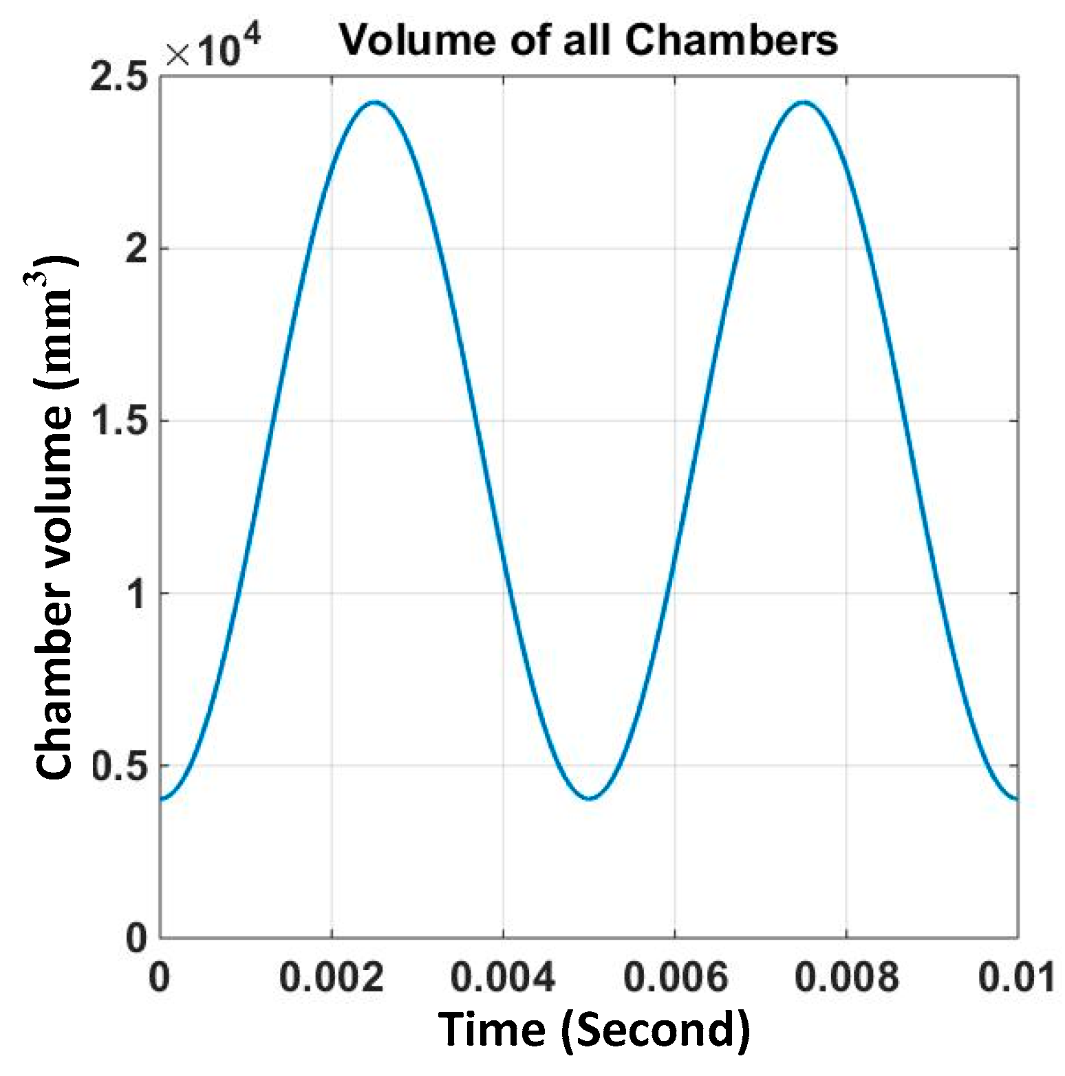
For the MSRE working in steady state, the spindle speed was a certain number, and the volume of each chamber changed periodically with time in a sine-like waveform. Given the main structural parameters for MSRE in Table 1, with an operation frequency of 100 Hz, the volume of each chamber (working volume for the medium) versus time over one spindle circle is given in Figure 6. Moreover, the time rate of change for the chamber volume is obtained at any instant of time from Figure 6.
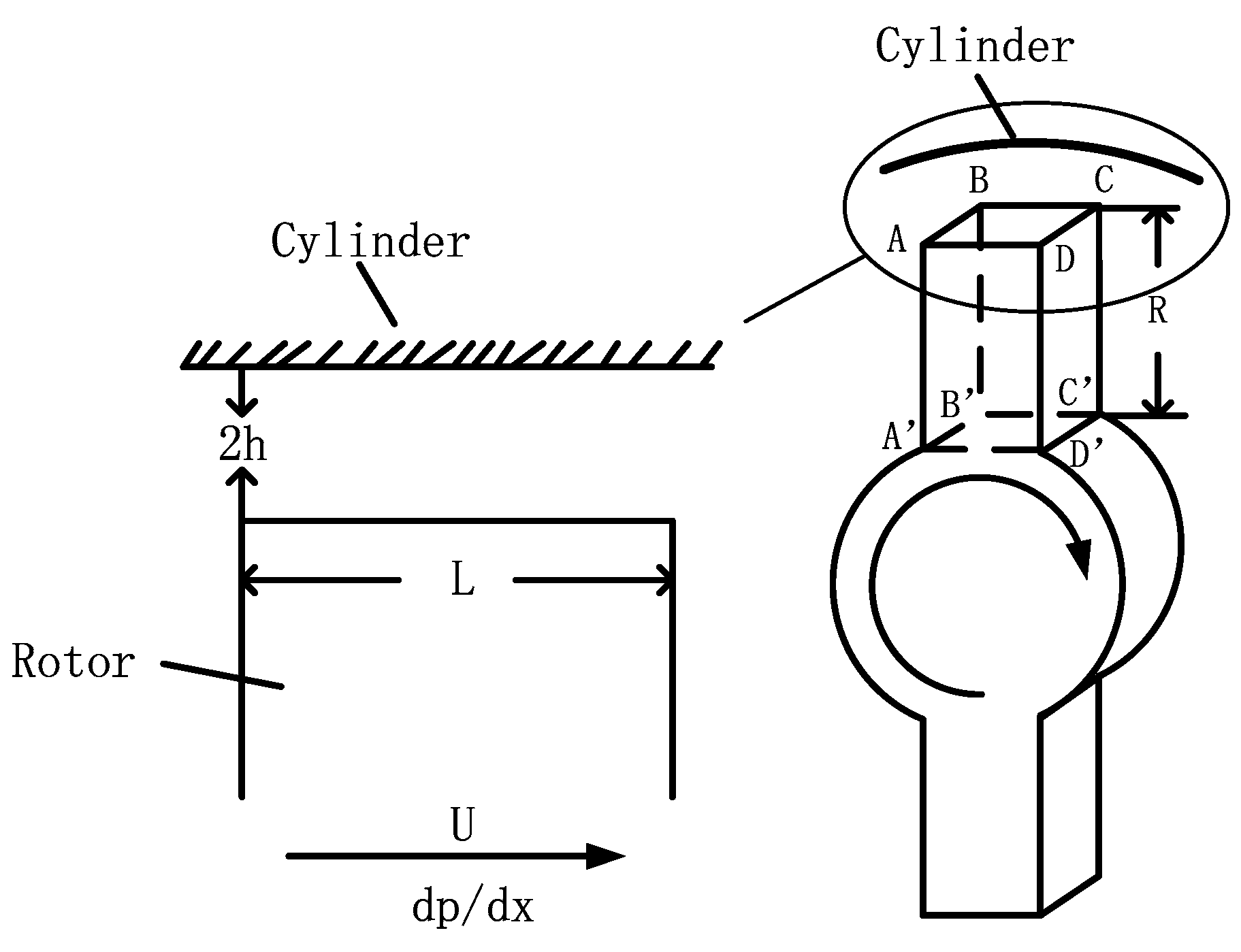
A certain gap should be maintained between the rotors and the wall surfaces inside the chamber especially for engines in micro and mesoscales, so that the rotors can rotate with less friction. However, for MSRE, because the working fluid in each chamber is influenced by the neighboring two chambers through leakage flow, the engine performance is weakened by the leakage effect more seriously. For each rotor arm of the MSRE, the leakage flows exist in three interfaces between the rotor and the stator (Figure 7), that is, one clearance on top of the arm and two clearances on both axial sides of the arm. Without consideration of the rarefaction effects, the clearance leakage can be described by the classical Couette–Poisueille flow with no slip boundary conditions and the fluid velocity u ( y ) in stream wise is given by [37]:
u ( y ) = 1 2 μ d p d x ( y 2 h 0 2 ) + 1 2 U ( 1 + y h 0 )  
where h 0 is the half of the gap height H , y is the coordinate across the gap, μ is the dynamic viscosity of the leakage flow, and U is the velocity of the rotor.
Thus, the leakage mass flow rate m ˙ l 1 for the clearance on top of the arm can be obtained via:
m ˙ l 1 = ρ H h 0 + h 0 u ( y ) d y  
The leakage mass flow rate m ˙ l 2 for the clearance on both axial sides of the arm is obtained via:
m ˙ l 2 = 2 ρ r i n r o u t h 0 + h 0 u ( y ) d y d r  
where r i n is the hinge-radius, r o u t is the arm-radius.
And the total leakage mass flow rate is given as:
m ˙ l = m ˙ l 1 + m ˙ l 2  

3.1.2. Solution Method for the Thermodynamic Model

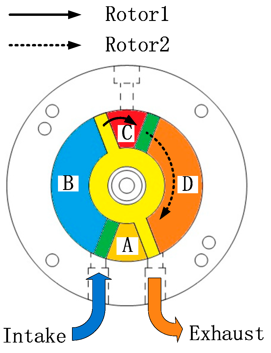
Under a stable working station, each of the four chambers in the MSRE will finish a complete four-stroke process during one spindle circle, or a total of four similar cycles. Figure 8 shows the thermo-state of each chamber at a certain moment, in which chambers A, B, C and D are about to intake, compress, expand, and exhaust, respectively. Since each stroke takes the same time, the combination of four distinct thermodynamic processes for each chamber during one quarter of spindle circle exactly matches a complete four-stroke process. Therefore, the thermo-process should be simulated in 1/4 cycles to obtain a comprehensive analysis of the thermodynamic characteristics of the MSRE. The variable step Runge–Kutta method (ode45, in Matlab) was adopted in this study to numerically solve the nonlinear ordinary differential equations established above. In the ode45 time integration scheme, a four-sub-step method was used to provide the candidate solution, and a five-sub-step method to control the calculation error. As an adaptive step numerical solution, this scheme was able to solve the Nonstiff differential equation with rather high accuracy in a short time. We refer to the initial parameters taken in the simulation for the MICSE [31]; the parameters used in this work are provided in Table 2.

3.2. Results of Thermodynamic Simulation for MSRE and Discussion

Based on the designed prototype, a preliminary analysis on the basic thermodynamic characteristics was carried out, in which the heat transfer losses through walls were not considered. With a compression ratio of 6, the working frequency and clearance size were two dominant factors of the engine performance, the influences of which will be elaborated in the following part.

3.2.1. Basic Thermodynamic Characteristics of the MSRE

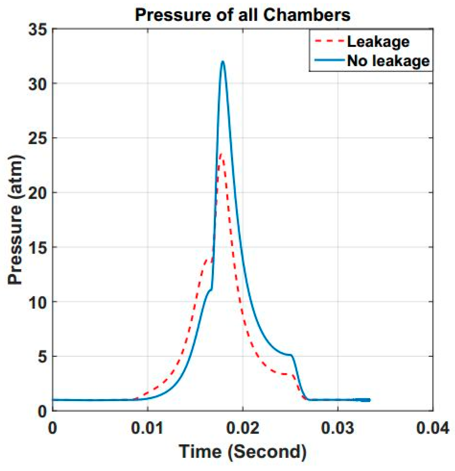
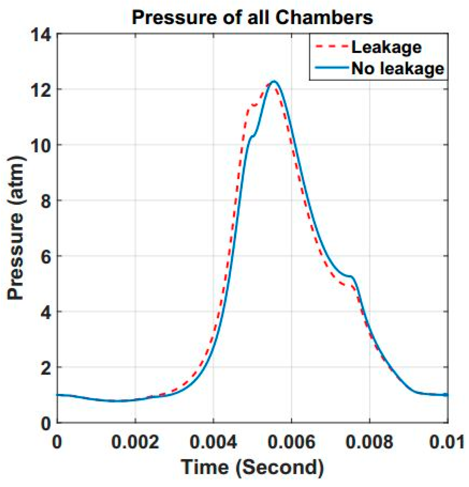
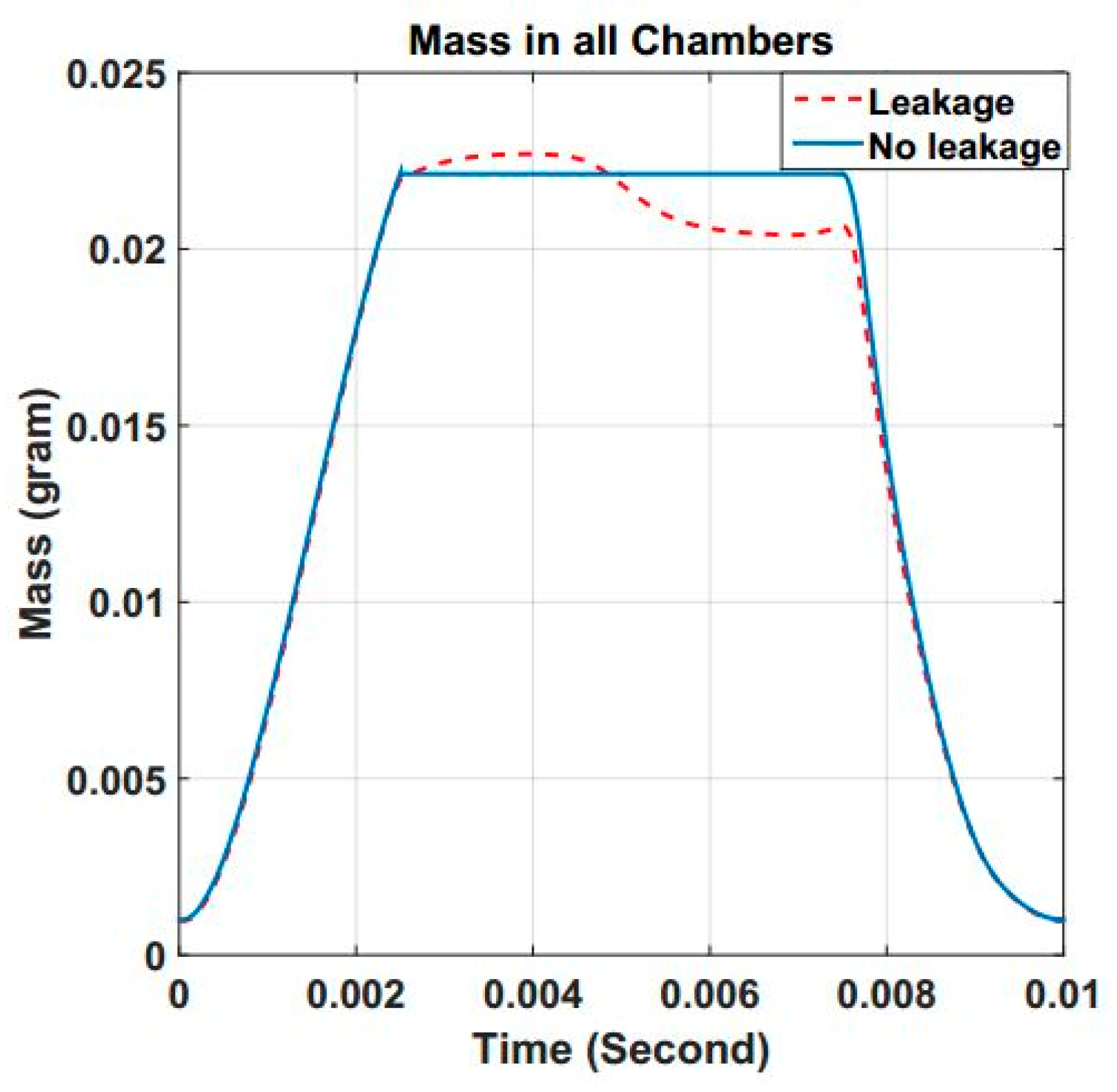
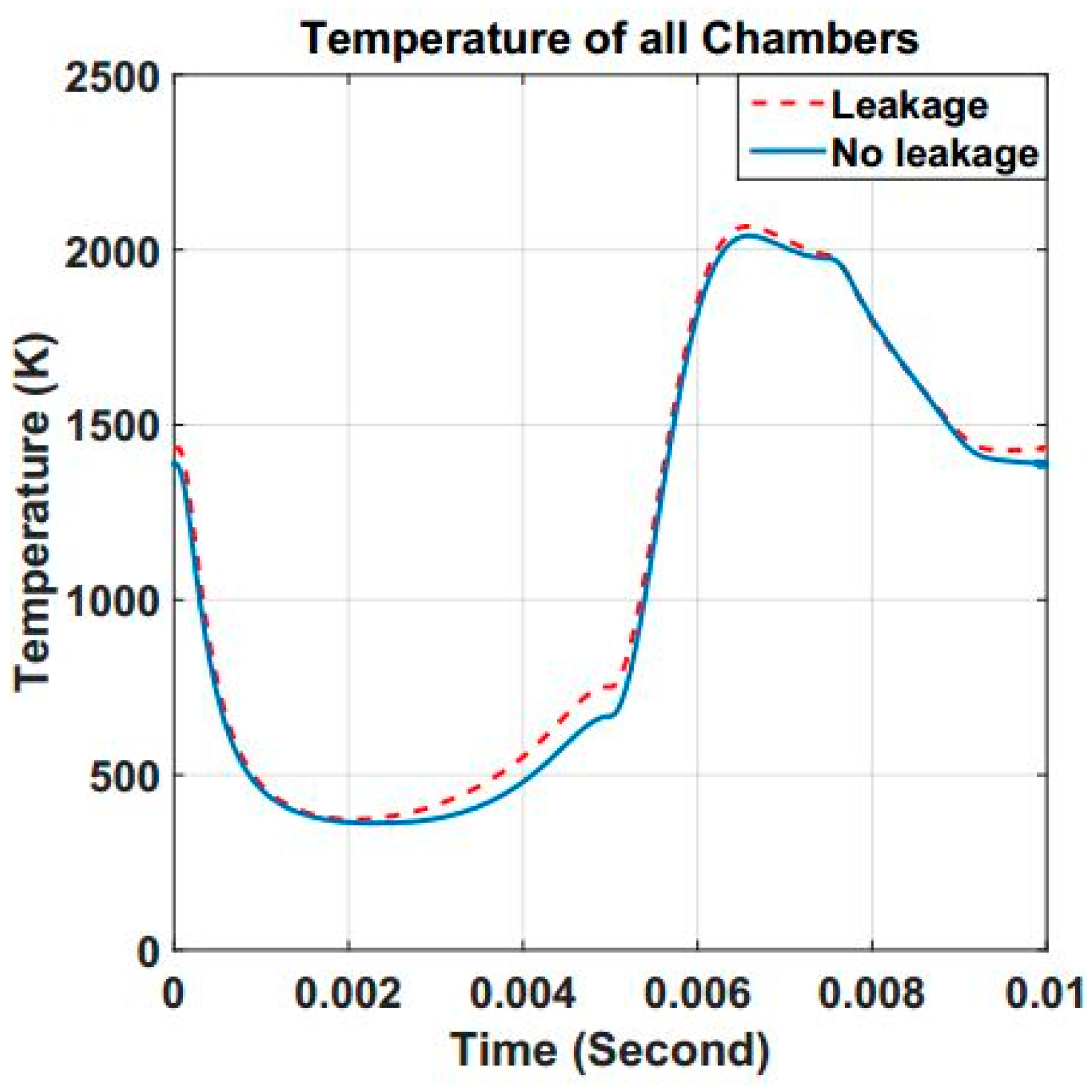
As the most influential irreversible loss, the leakage effect reduces the engine performance drastically. The thermodynamic characteristics with and without consideration of the leakage effect using a gap height of 20 μm were compared. Figure 9, Figure 10, Figure 11, Figure 12, Figure 13, Figure 14, Figure 15 and Figure 16 show the simulation results at the working frequency of 30 Hz and 100 Hz.
As shown in Figure 9, for the MSRE at 30 Hz frequency, trends of the pressure change during one cycle with and without leakage effect were similar. The pressure of the working fluid continuously increased for the intake and compression processes, peaked at the end of combustion process, and slowed down during the expansion and exhaust strokes. However, compared to the results with no leakage flow, the pressure curve with leakage effect over the entire compression stroke was higher, however, that over the entire expansion stroke was lower. Because the gas with higher pressure and temperature in the combustion chamber could flow into the neighboring compression chamber through the clearance, the pressure in the compression chamber was raised and vice versa, the pressure in the combustion chamber was lowered. In comparison to the results in Figure 10 for the MSRE at 100 Hz frequency, the discrepancy caused by the leakage effect was more serious for the engine at lower frequency, in which the peak pressure was dramatically reduced. In other words, it was inferred that the leakage influence can be suppressed by higher working frequency.
The changing processes of working fluid mass over one cycle are given in Figure 11 and Figure 12. Without leakage flow, the fluid mass in one certain chamber increased in the intake stroke, remained constant for compression and expansion stokes, and declined rapidly in the exhaust stroke. However, things were quite different when the leakage effect was considered. At the end of the intake process, since the pressure is higher, a small amount of the fresh fuel mixture was extruded to the neighboring exhaust chamber and the fluid mass slightly decreased. In the compression stroke, the fluid mass at the initial stage increased with the more reception of gas from the combustion chamber. But at the later stage, the pressure increased rapidly and more fluid flowed into the neighboring intake chamber. Thus, the fluid mass decreased until the end of the combustion process. Then, the fluid mass increased again because of the gas injection from the neighboring compression chamber. Certainly, this discrepancy is more serious for a lower working frequency where the amplitude of fluctuation will be much higher.
The temperature of the working fluid changes in accordance with pressure and the curves are expressed in Figure 13 and Figure 14. Whether the leakage effect is considered or not, the fluid temperature changes in a similar trend, for a certain working frequency. However, influenced by this irreversible loss, the fluid remains heated for the entire cycle. The reason for the pressure changing process is given as follows.
Because of the leakage gaps, the compression and exhaust chambers were continuously injected by the working medium with higher temperature from the adjacent combustion chamber, thereby resulting in their higher temperature. The heated exhaust process increased the initial temperature for the intake stroke, while the intake chamber was heated further by the leakage flow from the compression chamber. In addition, since the fuel combusted based on the temperature gained from the end of compression stroke, the temperature for the expansion stroke became higher accordingly. In conclusion, the progressive interactions between two neighboring chambers resulted in a higher temperature for the entire cycle, which was, essentially, caused by the leakage effect. Similarly, the engine with a low working frequency was more seriously influenced by the leakage effect.
Due to the leakage effect, pressure for the compression process raised, while pressure in the expansion process did just the opposite. Consequently, the indicated work of the engine was decreased. The lower the working frequency was, the more remarkable the reduction in output work was (Figure 15 and Figure 16).
It can also be observed that the four-stroke process for the engine with a low frequency (30 Hz) was close to the Otto cycle, because the fuel combusted in a nearly constant volume. However, with a higher operation frequency (100 Hz), the engine cycle deviates from the Otto cycle, since the pressure in the combustion process increased gradually.

3.2.2. Influence of Operation Frequency on the Engine Thermodynamic Characteristics

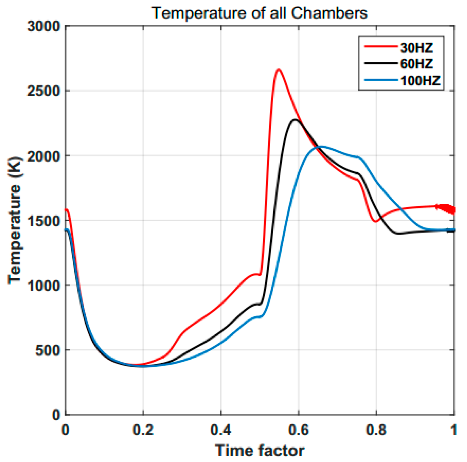
The analysis reveals that, even with the same gap size, different working frequencies will result in influences of leakage effect with distinct levels on the engine. Therefore, the impact of operation frequency on the thermodynamic characteristics of the MSRE was investigated. With a gap height of 20 μm, simulation results for the engine at a series of frequencies (i.e., 30 Hz, 60 Hz and 100 Hz) are taken for this study (Figure 17, Figure 18, Figure 19 and Figure 20). For the convenience of analysis, the dimensionless time τ is defined as
τ = t T c y c l e  
where t is real time (s), T c y c l e is the duration for one total cycle (s).
With a burn duration time, the ratio of combustion time to one expansion stroke will be larger when the engine operates at a higher frequency. Thus, the pressure-rise effect resulting from combustion was further weakened by the pressure drop effect caused by volume expansion, that is, the peak pressure after combustion was cut down. As Figure 17 shows, for the studied three working conditions, the lower frequency, and the higher peak pressure. However, higher frequency usually means less time allowed for leak flow, thereby playing a certain role in suppressing leakage effect. Thus, the pressure for engine at higher frequency will be lower during intake and compression strokes, until after combustion. But it increases for the expansion and exhaust process, compared to the simulation results for lower-frequency cases. As a consequence, the difference between the pressure value for the intake end and that for the exhaustion end was narrowed. Therefore, the reduction value of the working fluid mass at the end of the intake process is lessened (Figure 18). Under the working frequency of 100 Hz, the mass reduction trend even disappeared entirely. Furthermore, the mass fluctuation caused by the leakage effect for the engine at a higher frequency was much smaller. As for the changing process of temperature shown in Figure 19, explanations for the pressure change are applicable here.
The overall engine performance at a series of operating frequencies is shown in Figure 20. Results show that the MSRE cannot function properly when the operating frequency was lower than 10 Hz, because both the engine efficiency and power are negative. For frequencies larger than 10 Hz, the maximum efficiency and power individually corresponded to an optimal frequency value. The reason is given as follows. As the working frequency increased from 10 Hz, although the leakage mass flow nearly remains the same, the available time for leakage was reduced, resulting in a weakened leakage effect, thereby improving the engine efficiency. In addition, the engine power increased accordingly, because the time ratio to output work per unit time increased. However, once the operating frequency grew excessively, the burn duration time could not be ignored, and the incomplete combustion could lead to more severe deterioration of the engine performance. As a consequence, two optimal values of frequency exist for engine performance and power.
At an operating frequency of 55 Hz, the engine reached the optimum thermal efficiency (23.62%) with a power of 2458.18 W, which is approximately 4.72 times of the micro-turbine’s efficiency (5%). When the operating frequency is 95 Hz, it will reach the maximum power (3442 W) with a thermal efficiency of 18.96%. The corresponding power weight ratio is 1.72 kW/kg, about 5.21 times of that for the MICSE (0.33 kW/kg) and 3.44 times of that for conventional IC engines (0.5 kW/kg).

3.2.3. Combined Effect of Gap Height and Operating Frequency

Since the compression ratio of the engine has been designated as 6, working frequency and clearance size were the two parameters that determined the engine performance, and their combined effect should be investigated.
Figure 21 shows the change process of engine efficiency with gap length for different gap heights. Under a certain gap height, as the gap depth increases linearly, the thermal efficiency rises, and the increase will gradually slow down. However, with the increase in gap height, the engine efficiency will be sharply reduced, especially for values larger than 20 μm. When the gap height is 50 μm and the gap depth is less than 8 mm, the engine efficiency will be less than zero, indicating that it is incapable of self-operation.
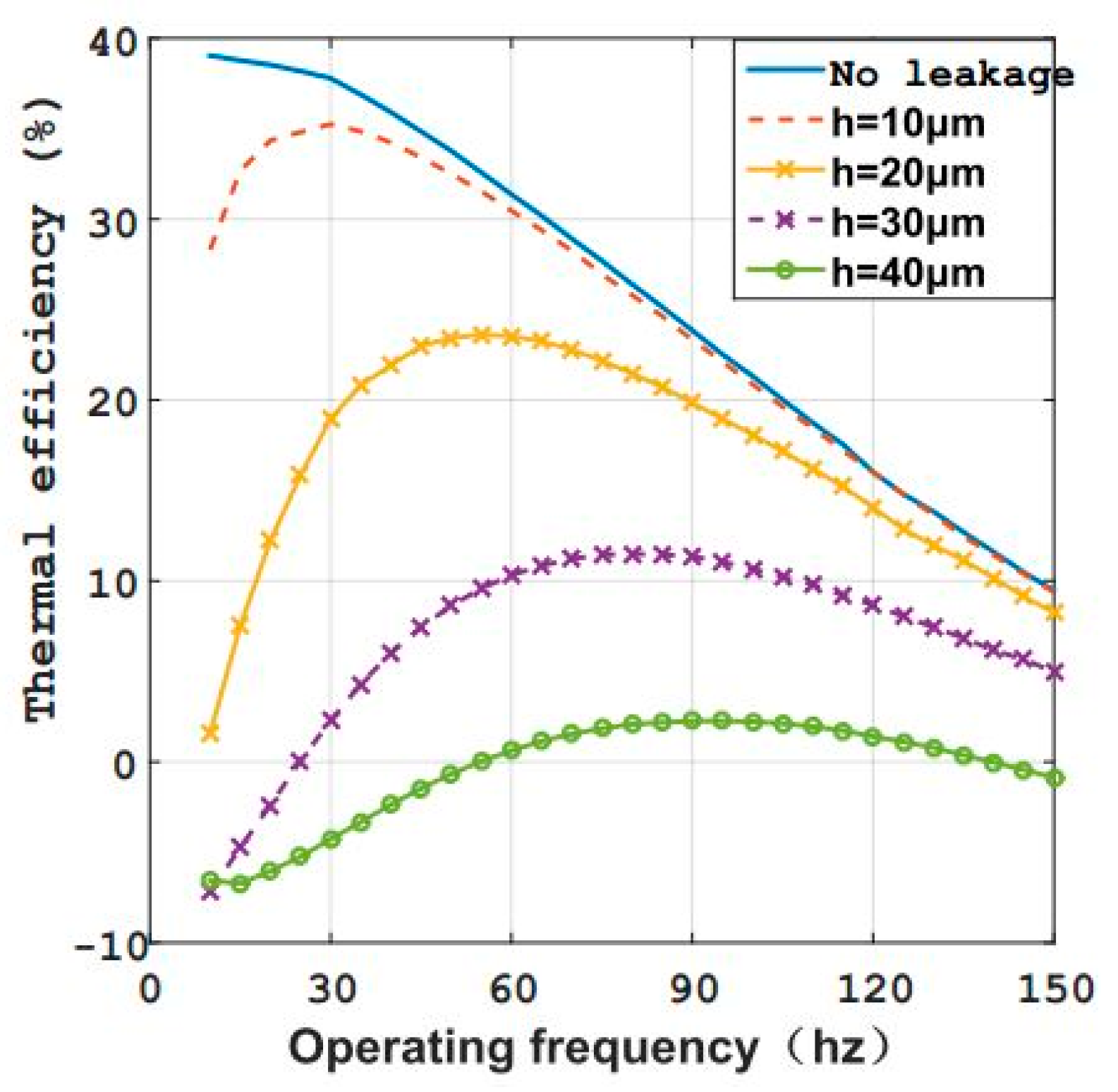
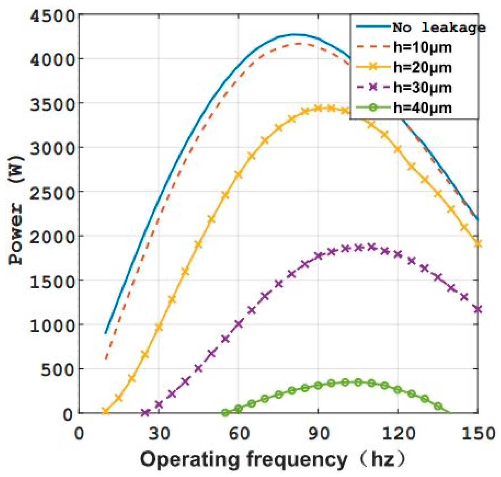
In consideration of the leakage effect, the optimal values of frequency exist for engine performance and power. As shown in Figure 22 and Figure 23, the larger the gap height was, the lower the corresponding optimum efficiency and power value were. Moreover, the feasible range of working frequency becomes narrower. For example, when the gap height was larger than 40 μm, the engine could only work at a frequency range of 55 Hz to 135 Hz, with a maximum efficiency of no more than 2.25%, and a power lower than 350 W. In addition, the maximum thermal efficiency dropped dramatically from 35% for a 10 μm gap height to 2% for a 40 μm gap height. Under a certain gap height, the optimal frequency value for engine efficiency was lower than that for engine power. Overall, the optimal frequencies increased as the gap height grew.
The results indicate that, although affected by the working frequency and leakage, the engine performance was dominated by the leakage effect when it worked at a low frequency. However, with the increase in working frequency, the leakage influence gradually weakened. Once the frequency was high enough, the engine performance approached that result without leakage effect; that is, the working frequency became the dominant parameter for engine performance. For that case, the leakage can be neglected, especially for a smaller gap height.

4. Preliminary Experiments on the Micro Swing Rotor Engine

A prototype was designed and fabricated in mesoscale to validate the novel engine proposed in this study. Based on the established experimental platform, preliminary tests were carried out on the prototype for cold and thermal states, which could verify the feasibility of MSRE

4.1. Establishment of the Experimental Platform

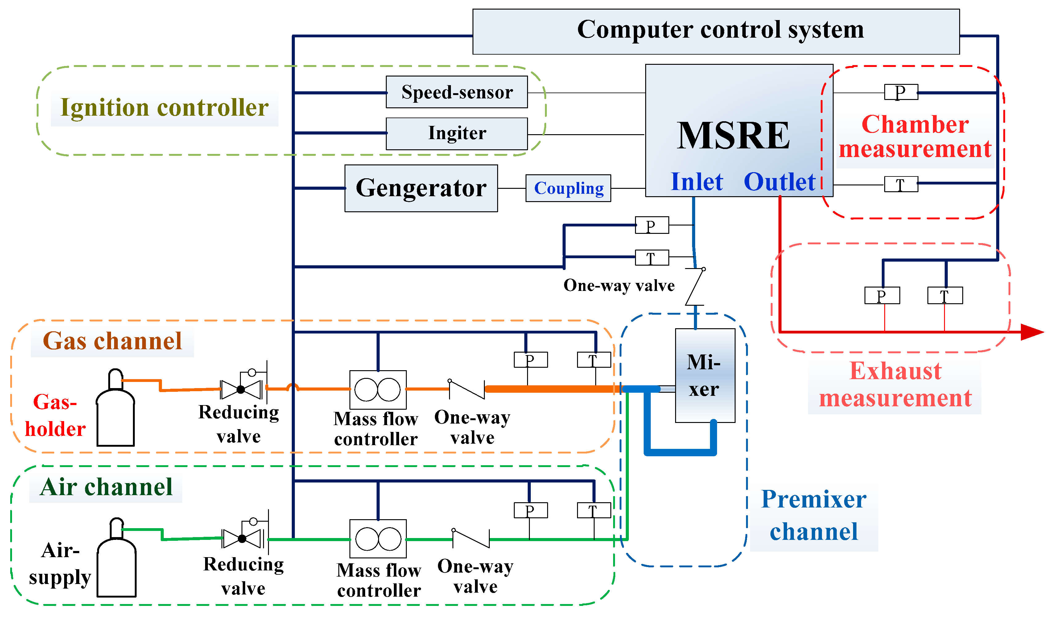
The experiment platform was composed of four parts, namely, the prototype system, the fuel supply system, the ignition control system, and the parameter acquisition and measurement system (Figure 24). As the main body of this platform, the prototype system output power by consuming hydrocarbon fuels, which was comprised of a prototype and a small generator. A gas-channel assembly, an air-channel assembly, and the pre-mixer made up the fuel supply system to provide combustible mixture for the engine. Consisting of a sparking plug, a high voltage coil, and a speed sensor (hall element), the ignition controller was responsible for the combustion of inflammable gas at high frequency (100 Hz). In cooperation with a group of thermocouples and dynamic pressure sensors, the computer control system made a parameter acquisition and measurement system to monitor the changing process of thermodynamic state in each chamber. In Figure 24, letters ‘P’ and ‘T’ represent the pressure and temperature measuring points, respectively.
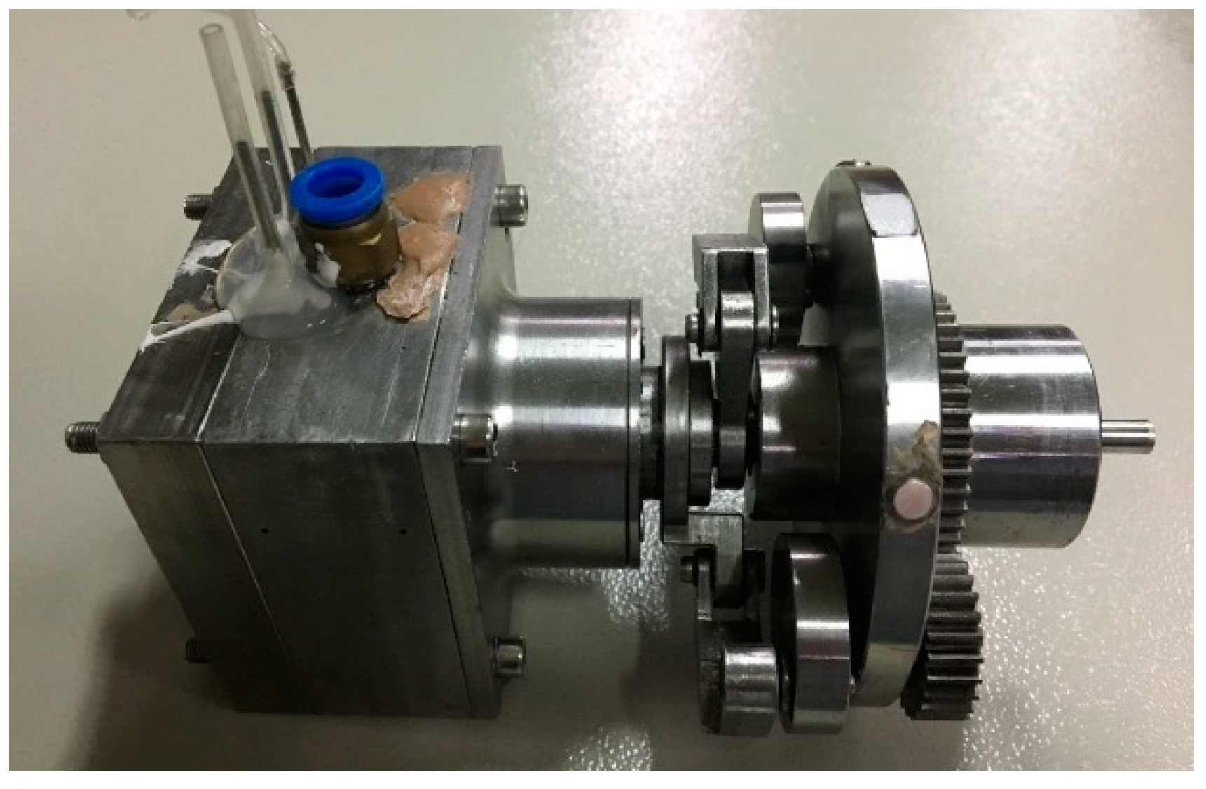
With less than 2 kg weight, the prototype was designed to be in a high coaxial structure, especially for the driver and cylinder assemblies, with a main size of 75 mm × 75 mm × 50 mm (Figure 25). A coupling was used to link the generator and the prototype body in the test rig; the overall prototype is shown in Figure 26.
Butane and air were used as fuel reactants here. The scopes of mass flow controllers were 4 g/s and 0.5 g/s for the gas and air channels, respectively, with an accuracy of ±0.1% flow scope. The spiral rise mixing of counter flow occurred in the pre-mixer, so that the reactants were fully mixed in a certain proportion controlled by mass controllers.
The micro thermocouples (OMEGA) in K-Type with an end diameter of 0.5 mm were adopted to measure the chamber temperature in the MSRE. Connected to a high-precision data acquisition devices (Agilent U2802A and U2356A), the maximum sampling rate of the thermocouples was up to 500 kHz and the measure accuracy was ±0.02% of reading. Pressure in the chambers was measured by high frequency dynamic pressure sensors (sqsensor, CYG502ASL) with a maximum sampling rate of 20 kHz. The measure scope of the sensor was 500 kPa and the measurement accuracy of ±0.25% of its scope. According to the circumferential positions of the dual-rotor in one cycle, that is, the changing process of one certain chamber distribution, six measuring points around the cylinder base were necessary to obtain the successive parameter change in one chamber for one complete cycle. Two groups of measuring points were designed for temperature and pressure; the circumferential distribution for the probes is presented in Figure 27. Take chamber A, for example: a complete operation mode or the selection principle for the six measuring points is elaborated in Figure 28. For the other measuring parts shown in Figure 24, the pressure was tested by pressure-gauges, with a scope of 200 kPa and an accuracy of ±0.4% FS. During the experiments, all the measuring conditions had to be kept coincident, so that the flow interpretation was affected as little as possible [41].
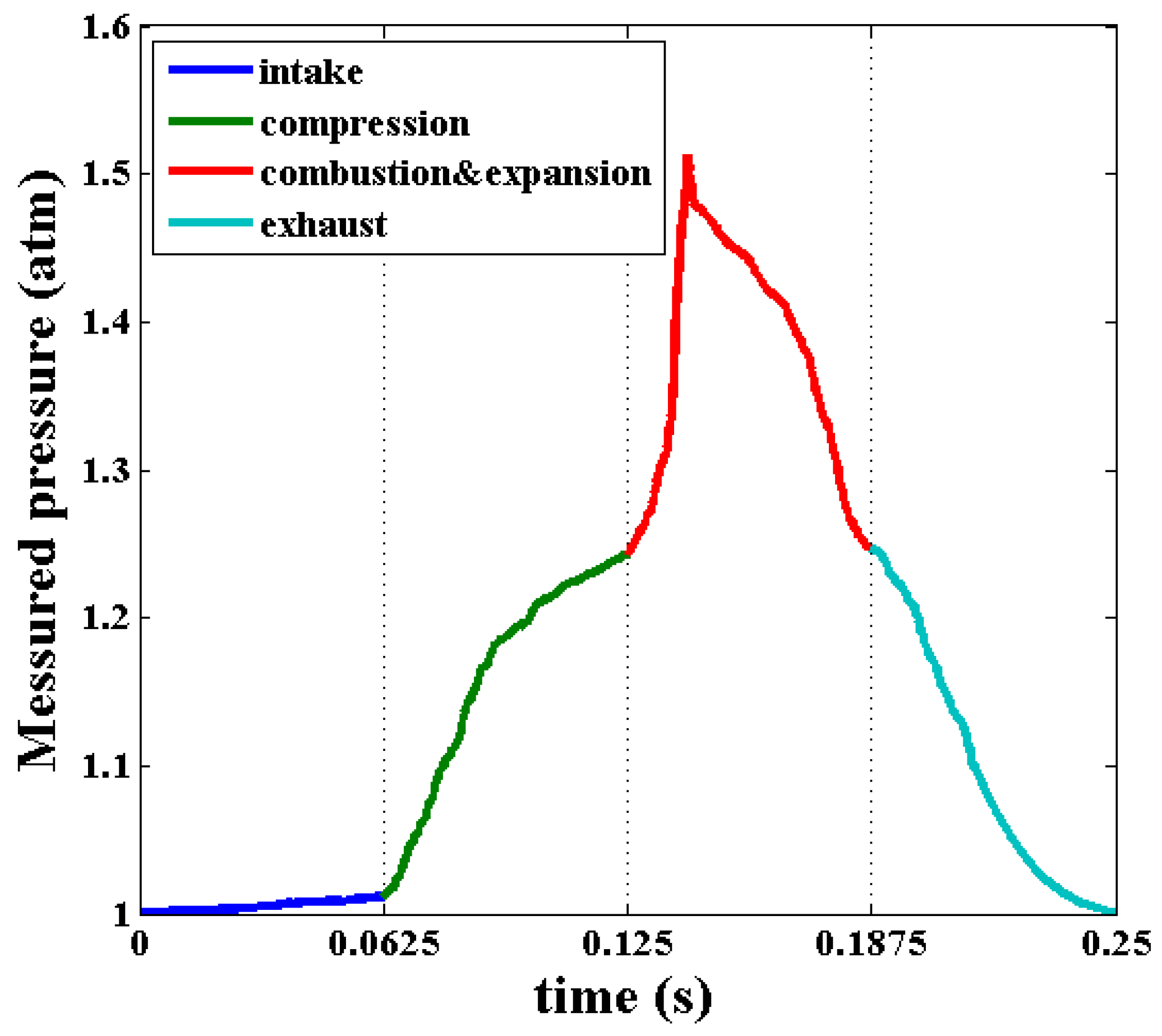
Because the following analysis was conducted on the basis of pressure measurements, some pressure uncertainty estimation for this experiment was necessary [42]. The pressure measurement error in this study was determined by the high frequency dynamic pressure sensors with an accuracy of ±0.25% of its scope (500 kPa), that is ±0.0125 atm. In Figure 29 and Figure 30, the measured pressures are in the range between 1 atm and 1.5 atm. Compared to the smallest value, the experimental error was controlled within ±1.25% and, compared to the highest value, the measurement error was within ±0.84%. Therefore, the experimental uncertainty was totally acceptable and could have little effect on the final test conclusion and explanations. That is why in Figure 29 and Figure 30 the errors were not marked.

4.2. Cold State Test with Pressure-Air Blow

Disregarding pressure-rise, brought out by the combustion reaction, the cold state tests were performed by charging pressure-air into the engine through the spark-plug port at the time when combustion was to occur. A survey of pressure changing process was obtained to test the engine performance in cold state, which was necessary for investigating the influence of unthermal factors, such as the leakage effect and mechanical friction.
With the flowing-in air at the pressure of 2.0 atm, a typical experimental result for the cold state engine at 240 rpm speed is shown in Figure 29 (in relative value). Since the assembly error for this prototype was controlled under 100 μm, the severe leakage caused a dramatic pressure loss; the peak value was just a little more than 0.5 atm. However, the pressure changing trend was similar to the simulation result, which could be used to demonstrate the structure feasibility of the MSRE.

4.3. Combustion Test for Engine Operation at Thermal State

The mixture gas was charged into the prototype engine and combustion test was carried out. With an entrance pressure of 0.12 atm (relative value) just before the intake port, the complete combustion process in one chamber was obtained (Figure 31); the results of the measured pressure for the engine operating at 150 rpm are given in Figure 30. It is explicit that, influenced by other irreversible effects, especially the leakage flow, the prototype could not generate net power at the present low frequency, which was consistent with the simulation results.
In conclusion, though creativeness and feasibility of MSRE were proven in this study, deep works on the prototype design and fabrication are necessary to further improve its performance.

5. Conclusions

As a potential system for power supply, great developments in the micro heat engine have been accomplished. In view of the defects (e.g., complex structure, difficultly in sealing, and low power-to-volume ratio) of existing engine types, the MSRE was proposed in this paper. Preliminary kinematic and thermodynamic analyses were conducted. The major conclusions are summarized as follows:
(1)
The proposed MSRE in four-stroke is composed of cylinder assembly and driver assembly, which can make the best of advantages for the micro swing engine and other IC engines. Without any complex components, surface sealing is applicable and the working frequency of this engine is relatively low at approximately 100 Hz order. Since available volume in cylinder assembly is high, the power to weight ratio is remarkable.
(2)
In accordance with the operating characteristics of the MSRE, the design principle of the driver assembly was proven, so that the required periodical pursue motion of the two rotors was accomplished. In the prototype, the bar-length ratio of the crank-rocker mechanism was designed to be 3:0.5973:2.7402:1.2503; the rotor-thickness angle was 10°. With a compression ratio of 6, the volume of each chamber in the MSRE varied in a sine-like waveform, meeting well the design requirements.
(3)
Considering leakage effect, the thermodynamic model for the engine in steady working cycle was established. Simulation results indicated that the engine performance suffers poorly due to the leakage influence, especially when working at low frequencies. Thus, the effect of leakage size was analyzed. As the gap height increased, the engine efficiency diminishes sharply.
(4)
Gap height and the operation frequency were demonstrated as the two dominant factors that affect the engine performance. Analyses show that, under certain gap height, the MSRE must work at a specific frequency range, and the corresponding optical values exist for engine efficiency and power. With a gap height of 20 μm, the MSRE will reach the maximum efficiency of 23.62% at 55 Hz and achieve its maximum power of 3442 W at 95 Hz. Compared to the Micro-turbine by IHI or MICSE, the MSRE has remarkable advantages in power weight ratio and efficiency.
(5)
An experimental platform has been established and a preliminary test on the engine operation characteristics was conducted. In the cold state test with pressure-air blow, the experimental pressure changing trend was similar to the numerical result. Moreover, the research on combustion for the MSRE at thermal state showed that a full combustion process of butane was realized when the engine worked at 150 rpm.
(6)
Theoretical feasibility and creativity of MSRE were validated primitively by simulation analysis, together with the experimental test in this study. This work contributes a lot to the development of micro power systems.

Author Contributions

C.X. performed the data analyses and wrote the manuscript; Z.Z. contributed significantly to analysis, experiment and manuscript preparation; G.H. proposed the conception of the study; T.Z. helped design the engine structure and perform the numerical simulations; J.X. helped perform the data analyses and manuscript preparation.

Funding

This research was funded by the National Basic Research Program of China (grant number 2014CB239602) and the Funding of Jiangsu Innovation Program for Graduate Education (grant number KYLX15_0258). And The APC was funded by 2014CB239602.

Acknowledgments

This work was supported by the National Basic Research Program of China (NO. 2014CB239602) and the Funding of Jiangsu Innovation Program for Graduate Education (NO. KYLX15_0258).

Conflicts of Interest

The authors declare no conflicts of interest.

References

  1. Fernandez-Pello, A.C. Micropower generation using combustion: Issues and approaches. Proc. Combust. Inst. 2002, 29, 883–899. [Google Scholar] [CrossRef] [Green Version]
  2. Sher, E.; Sher, I. Theoretical limits of scaling-down internal combustion engines. Chem. Eng. Sci. 2011, 66, 260–267. [Google Scholar] [CrossRef] [Green Version]
  3. Ju, Y.; Maruta, K. Microscale combustion: Technology development and fundamental research. Prog. Energy Combust. Sci. 2011, 37, 669–715. [Google Scholar] [CrossRef]
  4. Taywade, U.W.; Deshpande, A.A.; Kumar, S. Thermal performance of a micro combustor with heat recirculation. Fuel Process. Technol. 2013, 109, 179–188. [Google Scholar] [CrossRef]
  5. Walther, D.C.; Ahn, J. Advances and challenges in the development of power-generation systems at small scales. Prog. Energy Combust. Sci. 2011, 37, 583–610. [Google Scholar] [CrossRef]
  6. Chou, S.K.; Yang, W.M.; Chua, K.J.; Li, J.; Zhang, K.L. Development of micro power generators—A review. Appl. Energy 2011, 88, 1–16. [Google Scholar] [CrossRef]
  7. Epstein, A.; Senturia, S.; Al-Midani, O.; Anathasuresh, G.; Epstein, A.; Senturia, S.; Al-Midani, O.; Anathasuresh, G.; Ayon, A.; Breuer, K.; et al. Micro-heat engines, gas turbines and rocket engines—The MIT Microengine project. In Proceedings of the 28th AIAA Fluid Dynamics Conference, Snowmass Village, CO, USA, 29 June–2 July 1997. [Google Scholar]
  8. Epstein, A.H. Millimeter-Scale, MEMS Gas Turbine Engines. In Proceedings of the ASME Turbo Expo 2003, Atlanta, GA, USA, 16–19 June 2003. [Google Scholar]
  9. Isomura, K.; Tanaka, S.; Togo, S.; Esashi, M. Development of high-speed micro-gas bearings for three-dimensional micro-turbo machines. J. Micromech. Microeng. 2005, 15, S222. [Google Scholar] [CrossRef]
  10. Isomura, K.; Murayama, M.; Teramoto, S.; Hikichi, K.; Endo, Y.; Togo, S.; Tanaka, S. Experimental verification of the feasibility of a 100 W class micro-scale gas turbine at an impeller diameter of 10 mm. J. Micromech. Microeng. 2006, 16, S254–S261. [Google Scholar] [CrossRef]
  11. Tanaka, S.; Hikichi, K.; Togo, S.; Murayama, M.; Hirose, Y.; Sakurai, T.; Yuasa, S.; Teramoto, S.; Niino, T.; Mori, T.; et al. World’s smallest gas turbine establishing Brayton cycle. In Proceedings of the 7th International Workshop on Micro and Nanotechnology for Power Generation and Energy Conversion Applications, Freiburg, Germany, 27–29 November 2007; pp. 359–362. [Google Scholar]
  12. Lee, C.; Arslan, S.; Frechette, L.G. Design principles and measured performance of multistage radial flow microturbomachinery at low Reynolds numbers. J. Fluids Eng. Trans. ASME 2008, 130, 1349–1357. [Google Scholar] [CrossRef]
  13. Savoulides, N.; Jacobson, S.A.; Li, H.; Ho, L.; Khanna, R.; Teo, C.J.; Protz, J.M.; Wang, L.; Ward, D.; Schmidt, M.A.; et al. Fabrication and Testing of a High-Speed Microscale Turbocharger. J. Microelectromech. Syst. 2008, 17, 1270–1282. [Google Scholar] [CrossRef]
  14. Peck, J.; Jacobson, S.A.; Waitz, I.A. Design and Characterization of a Liquid-Fueled Microcombustor. J. Eng. Gas Turbines Power 2011, 133, 573–586. [Google Scholar] [CrossRef]
  15. Fu, K.; Knobloch, A.; Cooley, B.; Miyasaka, K. Micro-scale combustion research for applications to MEMS Rotary IC Engines. In Proceedings of the 35th ASME National Heat Transfer Conference, Anaheim, CA, USA, 10–12 June 2001. [Google Scholar]
  16. Fu, K.; Knobloch, A.; Martinez, F.; Walther, D.; Fernandez-Pello, C.; Pisano, A.P.; Liepmann, D. Design and fabrication of a silicon-based MEMS rotary engine. In Proceedings of the International Mechanical Engineering Congress and Exposition (IMECE), New York, NY, USA, 11–16 November 2001. [Google Scholar]
  17. Lee, C.H.; Jiang, K.C.; Jin, P.; Prewett, P.D. Design and fabrication of a micro Wankel engine using MEMS technology. Microelectron. Eng. 2004, 73, 529–534. [Google Scholar] [CrossRef]
  18. Sprague, S.B.; Park, S.W.; Walther, D.C.; Pisano, A.P.; Fernandez-Pello, A.C. Development and characterization of small-scale rotary engines. Int. J. Altern. Propuls. 2007, 1, 275–293. [Google Scholar] [CrossRef]
  19. Liu, Y.; Li, W.; Yang, C.; Song, R. Design and Test of Small-Scale Rotary Engine Power System. In Proceedings of the 2007 First International Conference on Integration and Commercialization of Micro and Nanosystems, Sanya, China, 10–13 January 2007; pp. 47–51. [Google Scholar]
  20. Wang, W.; Zuo, Z.; Liu, J. Miniaturization limitations of rotary internal combustion engines. Energy Convers. Manag. 2016, 112, 101–114. [Google Scholar] [CrossRef]
  21. Deng, H.; Pan, C.Y.; Wang, X.C.; Zhang, L.; Deng, L. Comparison of two types of twin-rotor piston engine mechanisms. J. Cent. South Univ. 2013, 20, 363–371. [Google Scholar] [CrossRef]
  22. Deng, H.; Pan, C.Y.; Xu, X.J.; Zhang, X. Mathematical modeling and analysis of gas torque in twin-rotor piston engine. J. Cent. South Univ. 2013, 20, 3536–3544. [Google Scholar] [CrossRef]
  23. Xu, H.; Zhang, L.; Pan, C.; Zhang, X. Design and dynamic characteristic prediction of air-powered twin-rotor piston engine. J. Cent. South Univ. 2015, 22, 4585–4596. [Google Scholar] [CrossRef]
  24. Yang, W. MEMS free-piston knock engine. Poster presentation. In Proceedings of the 28th International Symposium on Combustion, Edinburgh, UK, 30 July–4 August 2000. [Google Scholar]
  25. Aichlmayr, H.T.; Kittelson, D.B.; Zachariah, M.R. Miniature free-piston homogeneous charge compression ignition engine-compressor concept—Part I: Performance estimation and design considerations unique to small dimensions. Chem. Eng. Sci. 2002, 57, 4161–4171. [Google Scholar] [CrossRef]
  26. Aichlmayr, H.T. Design Considerations, Modeling, and Analysis of Micro-Homogeneous Charge Compression Ignition Combustion Free-piston Engines. Ph.D. Thesis, University of Minnesota, Minneapolis, MN, USA, 2002. [Google Scholar]
  27. Aichlmayr, H.T.; Kittelson, D.B.; Zachariah, M.R. Micro-HCCI combustion: Experimental characterization and development of a detailed chemical kinetic model with coupled piston motion. Combust. Flame 2003, 135, 227–248. [Google Scholar] [CrossRef]
  28. Sher, I.; Levinzon-Sher, D.; Sher, E. Miniaturization limitations of HCCI internal combustion engines. Appl. Therm. Eng. 2009, 29, 400–411. [Google Scholar] [CrossRef]
  29. Bai, J.; Wang, Q.; He, Z.; Li, C.; Pan, J. Study on methane HCCI combustion process of micro free-piston power device. Appl. Therm. Eng. 2014, 73, 1066–1075. [Google Scholar] [CrossRef]
  30. Wang, Q.; Zhang, D.; Bai, J.; He, Z. Numerical simulation of catalysis combustion inside micro free-piston engine. Energy Convers. Manag. 2016, 113, 243–251. [Google Scholar] [CrossRef]
  31. Mijit, K. Design, Analysis, and Experimentation of a Micro Internal Combustion Swing Engine. Ph.D. Thesis, University of Michigan, Ann Arbor, MI, USA, 2000. [Google Scholar]
  32. Dahm, W.; Mijit, J.; Mayor, R.; Qiao, G.; Benajmin, A.; Gu, Y.; Lei, Y.; Papke, M.; Wu, S. Micro internal combustion swing engine (MICSE) for portable power generation systems. In Proceedings of the 40th AIAA Aerospace Sciences Meeting and Exhibit, Reno, NV, USA, 14–17 January 2002. [Google Scholar]
  33. Gu, Y.; Dahm, W. Turbulence-augmented minimization of combustion time in mesoscale internal combustion engines. In Proceedings of the 44th AIAA Aerospace Sciences Meeting & Exhibit, Reno, NV, USA, 9–12 January 2006. [Google Scholar]
  34. Zhang, S.; Wang, J.; Guo, Z. Novel Micro Free-Piston Swing Engine and Its Feasibility Validation. Tsinghua Sci. Technol. 2005, 10, 381–386. [Google Scholar] [CrossRef]
  35. Zhang, S.; Guo, Z.; Wang, J. Performance analysis of a 2-stroke micro free-piston swing engine. Pet. Sci. 2009, 6, 313–318. [Google Scholar] [CrossRef]
  36. Gao, D.; Lei, Y.; Zhu, H.; Ni, J. Constant Speed Control of Four-stroke Micro Internal Combustion Swing Engine. Chin. J. Mech. Eng. 2015, 28, 971–982. [Google Scholar] [CrossRef]
  37. Zhou, X.; Zhang, Z.; Kong, W.; Du, N. Investigations of leakage mechanisms and its influences on a micro swing engine considering rarefaction effects. Appl. Therm. Eng. 2016, 106, 674–680. [Google Scholar] [CrossRef]
  38. Xia, C.; Zhang, Z.; Huang, G.; Xu, Y. Study on the new hybrid thermodynamic cycle for a developed MICSE with heat recovery process. Appl. Therm. Eng. 2018, 129C, 1135–1149. [Google Scholar] [CrossRef]
  39. Samanta, A.; Vinuesa, R.; Lashgari, I.; Schlatter, P.; Brandt, L. Enhanced secondary motion of the turbulent flow through a porous square duct. J. Fluid Mech. 2015, 784, 681–693. [Google Scholar] [CrossRef]
  40. Samanta, A.; Freund, J.B. A model supersonic buried-nozzle jet: Instability and acoustic wave scattering and the far field sound. J. Fluid Mech. 2015, 778, 189–215. [Google Scholar] [CrossRef]
  41. Vinuesa, R.; Schlatter, P.; Nagib, H.M. Role of data uncertainties in identifying the logarithmic region of turbulent boundary layers. Exp. Fluids 2014, 55, 1751. [Google Scholar] [CrossRef]
  42. Rezaeiravesh, S.; Vinuesa, R.; Liefvendahl, M.; Schlatter, P. Assessment of uncertainties in hot-wire anemometry and oil-film interferometry measurements for wall-bounded turbulent flows. Eur. J. Mech. B Fluids 2018, 72, 57–73. [Google Scholar] [CrossRef] [Green Version]
Figure 1. Composition of the overall structure for the micro swing rotor engine (MSRE).
Energies 11 02684 g001
Figure 2. Operation process of the micro swing rotor engine.
Energies 11 02684 g002
Figure 3. Schematic of the driving mechanism.
Energies 11 02684 g003
1. sun gear; 2,3. planet gear; 4,9. crank; 5,8. connecting rod; 6,7. rocker; 10. planet carrier.
Figure 4. Angular velocity of the two rotors.
Energies 11 02684 g004
Figure 5. Included angle between two arms.
Energies 11 02684 g005
Figure 6. Time-varying process for each chamber volume at a working frequency of 100 Hz.
Energies 11 02684 g006
Figure 7. Schematic of the leakage model.
Energies 11 02684 g007
Figure 8. Working cycle of the micro swing rotor engine in steady state.
Energies 11 02684 g008
Figure 9. Pressure of working fluid vs. time over one cycle (30 Hz).
Energies 11 02684 g009
Figure 10. Pressure of working fluid vs. time over one cycle (100 Hz).
Energies 11 02684 g010
Figure 11. Mass of working fluid vs. time over one cycle (30 Hz).
Energies 11 02684 g011
Figure 12. Mass of working fluid vs. time over one cycle (100 Hz).
Energies 11 02684 g012
Figure 13. Temperature of working fluid vs. time over one cycle (30 Hz).
Energies 11 02684 g013
Figure 14. Temperature of working fluid vs. time over one cycle (100 Hz).
Energies 11 02684 g014
Figure 15. P-V diagram over one cycle (30 Hz).
Energies 11 02684 g015
Figure 16. P-V diagram over one cycle (100 Hz).
Energies 11 02684 g016
Figure 17. Changing process of pressure at different frequencies.
Energies 11 02684 g017
Figure 18. Changing process of mass at different frequencies.
Energies 11 02684 g018
Figure 19. Changing process of temperature at different frequencies.
Energies 11 02684 g019
Figure 20. Thermal performances of MSRE at different frequencies.
Energies 11 02684 g020
Figure 21. Engine efficiency vs. gap length under different gap heights.
Energies 11 02684 g021
Figure 22. Engine efficiency vs. frequency under different gap heights.
Energies 11 02684 g022
Figure 23. Engine power vs. frequency under different gap heights.
Energies 11 02684 g023
Figure 24. The experimental platform for MSRE.
Energies 11 02684 g024
Figure 25. Prototype of the MSRE with high coaxiality.
Energies 11 02684 g025
Figure 26. Prototype system in the test rig.
Energies 11 02684 g026
Figure 27. Distribution of parameter-measuring points.
Energies 11 02684 g027
Figure 28. Selection principle of the six measuring points.
Energies 11 02684 g028
Figure 29. Experimental pressures vs. time for cold state over one cycle.
Energies 11 02684 g029
Figure 30. Experimental pressures vs. time for hot state over one cycle.
Energies 11 02684 g030
Figure 31. Combustion process for one chamber.
Energies 11 02684 g031
Table 1. Design parameters of the micro swing rotor engine in mesoscale.
ParametersValue
Compression ratio6
Minimum transmission angle for crank-rocker mechanism/°60
Arm thickness-angle/°10
Relative lengths of four-bar linkage l 1 : l 2 : l 3 : l 4 3:0.5973:2.7402:1.2503
Arm-diameter/mm60
Hinge-diameter/mm30
Arm-height/mm15
Table 2. Initial parameters of the micro swing rotor engine.
Initial ParametersValueInitial ParametersValue
Equivalence ratio0.8Exhaust port diameter/mm10
ReactantsC4H10, airIntake discharge coefficient0.7
Intake pressure/MPa0.1Exhaust discharge coefficient0.7
Intake temperature/K300Compression ratio6
Ambient pressure/MPa0.1Burn duration /ms2
Ambient temperature/K300Weibe function parameters [31]a = 5, m = 1
Intake port diameter/mm10