Article

Flux-Switching Permanent Magnet Machine with Phase-Group Concentrated-Coil Windings and Cogging Torque Reduction Technique

1
Department of Electronic Systems Engineering, Hanyang University, Ansan-si 426-791, Gyeonggi-do, Korea
2
School of Electrical Engineering, Shandong University, Jinan 250061, Shandong, China
*
Author to whom correspondence should be addressed.
Energies 2018, 11(10), 2758; https://doi.org/10.3390/en11102758
Submission received: 6 August 2018 / Revised: 12 October 2018 / Accepted: 12 October 2018 / Published: 15 October 2018

Abstract

:
We herein propose a novel high-torque-density flux-switching permanent magnet machine (FSPMM) which adopted phase-group concentrated-coil (PGCC) winding and a cogging torque reduction technique. The PGCC winding was applied to increase the torque density. In order to maximize the torque of the FSPMM that utilizes the PGCC windings, the performance according to stator slots/rotor poles combinations were compared. A machine which had 12 stator slots and 13 rotor poles (12S13P) was selected for its top average torque value. However, the 12S13P PGCC FSPMM contains high cogging torque that must be reduced. The cogging torque reduction technique is applied, and the parameters used in the technique are further optimized to achieve the target average torque, while suppressing the cogging torque as much as possible. The optimization process was performed with a collaboration of the genetic algorithm and Kriging method. The analysis results of the optimized design exhibited huge reductions in the cogging torque and eventually in the torque ripple from the initial machine, with reasonable average torque reduction. The entire work was evaluated experimentally using a manufactured prototype.

1. Introduction

Flux-switching permanent magnet machines (FSPMMs) have been researched for decades [1,2,3,4,5,6,7,8,9]. These studies were encouraged by the unique operating principle of the FSPMMs, and the advantages that emerge from their special structures [1]. The machine consists of a cogwheel-like rotor with no magnets, and a stator with magnets sandwiched between iron poles. Similar to the other stator-magnet-positioned machines, an FSPMM operates with modulation flux, unlike rotor-magnet-positioned machines that operate with the magnet pole flux. The advantages of the FSPMM stemming from its unique structure are high torque density compared to other permanent magnet machines, simplicity of magnet heat dissipation, and low demagnetization possibility [2,10,11]. Further, the use of phase-group concentrated-coil winding boosted the flux focusing effect of the FSPMM by gathering the poles into groups [2]. However, an FSPMM exhibits a drawback of high cogging torque due to its spoke-type-positioned magnets. This drawback causes high torque ripples that cause control difficulty, noise, and vibrations [9]. Thus, the cogging torque reduction is crucial for the machine to be properly used in applications. To decrease the cogging torque, various methods have been suggested [12,13,14,15,16]. In [12], the cogging torque of an FSPMM was reduced by assigning a notch to the stator and rotor. These notches changed the surfaces where the cogging torque occurred, to reduce the peak value of the cogging torque. However, it was difficult to design the small notches. In [13], the rotor pole of an FSPMM was added with a flange to reduce the cogging torque. This allowed the flux path to be smoothened, resulting in reduced cogging torque. However, the method required more materials for the flange. Similarly, [14] decreased the cogging torque by introducing dummy bridges on the FSPMM stator tooth, which also required more materials. [15] suggested a different method to reduce the cogging torque by injecting a harmonic current to cancel the torque ripple components with the harmonic components. Nevertheless, this method required difficult control methods to inject the harmonic current.
Herein, a novel FSPMM with PGCC windings and a technique for cogging torque reduction is proposed. First, stator and rotor pole combinations are studied to confirm the highest torque model for this winding. Subsequently, to decrease the cogging torque of the highest torque model, a technique to reduce the cogging torque is shown. The technique consisted of introducing round-shaped fillets to the rotor pole arc tip and adjusting the thickness of the iron part of the stator teeth. To effectively decrease the cogging torque and minimize the torque density reduction, the radius of the round-shaped fillet and the thickness of the iron part of stator teeth were optimized. Finally, the prototype of the optimized machine was built for the experiment. The prototype was tested to be compared with the three-dimensional finite element method (3D-FEM) analysis to verify this work.

2. FSPMM with PGCC Windings and Analysis Model

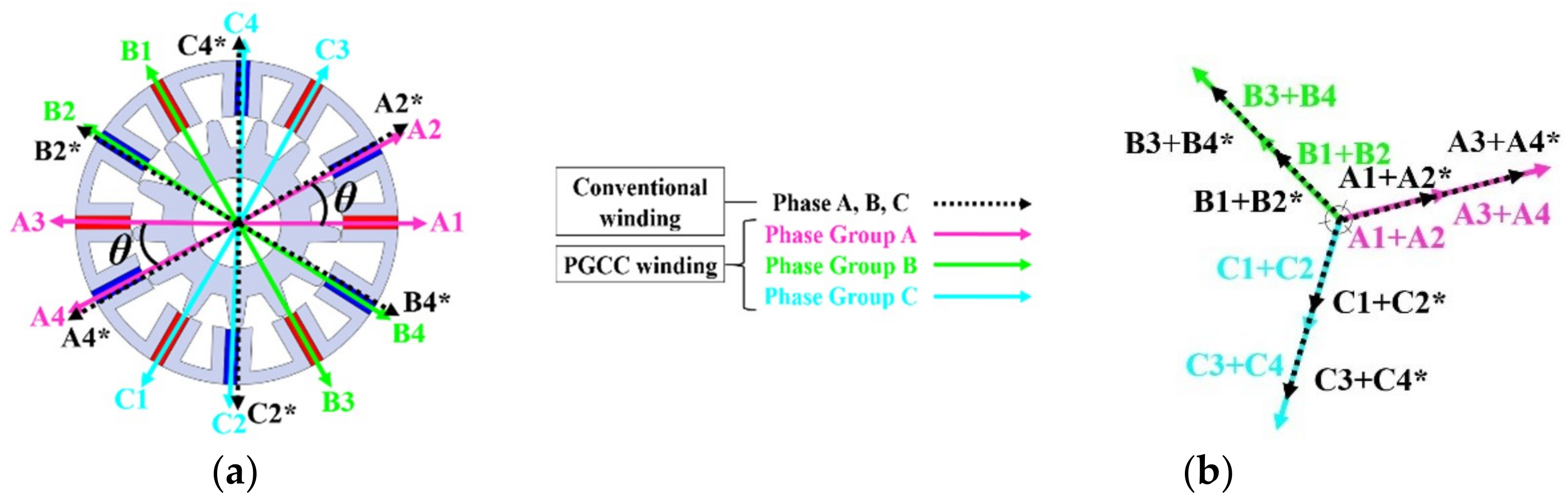
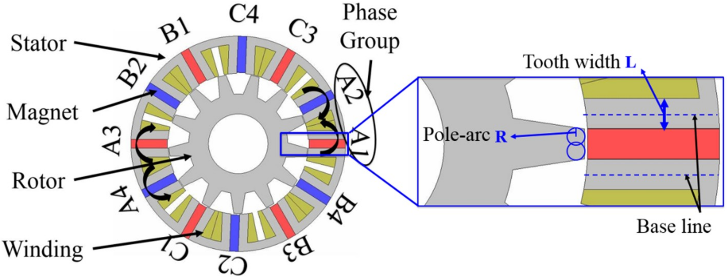
2.1. FSPMM with PGCC Windings

The PGCC winding topology was utilized to concentrate the resultant electromotive forces (EMFs) of each phase as closely as possible by manipulating the stator pole position. Consequently, the air gap flux density was enhanced, owing to a higher total EMF compared to conventional stator machines, thus resulting in a higher torque at the rated current [2]. In an FSPMM, owing to the spoke-type arranged permanent magnets, the flux focusing effect was already in use. Combining the PGCC winding topology and FSPMM topology, the torque boost was further enhanced.
To use the PGCC winding topology, specific equations for stator-rotor pole combinations were utilized as follows.
Stator   slot   number     Q = 3 n 1 n 2
Rotor   pole   number     P = 3 n 1 n 2 + n 2 / 2
Here, n 1 is the stator coil number of one phase group, and n 2 is the phase group number of each phase [2] (phase group is a group of coils included in one phase, as depicted in Figure 1). With different values of n 1 and n 2 , various combinations were possible. Several combinations of the FSPMM with the PGCC winding topology are listed in Table 1. Combinations with a higher number of poles were excluded considering the leakage flux and high iron loss, which was increased by the increased pole number.
To demonstrate the principle of the PGCC winding intuitively, the winding configuration and the resultant EMF vector of the 12S13P FSPMM is shown in Figure 2. The directions of each winding were set to induce the EMF vector of the same directions in each phase group to achieve the largest phase-group EMF vector. In Figure 2, black colored lines indicate the EMF vectors of conventional windings. Especially in Figure 2a, the conventional winding and PGCC winding had identical vectors of A1, A3, B1, B3, C1, and C3, but different vectors of A2, A4, B2, B4, C2, and C4. Angles θ between 1 and 2, 3 and 4, vectors had changed due to this difference. As the angles of conventional windings had smaller values compared to the PGCC winding, the sum of the EMF vectors gave a smaller result as shown in Figure 2b. The figures show that the arrangement of the PGCC windings results in each single direction for each phase group, consequently eliciting the back-EMF value to the limit with PGCC winding.

2.2. Analysis Models

To demonstrate the FSPMM with PGCC windings topology, a 12S13P FSPMM with PGCC windings is depicted in Figure 1. Table 2 shows the design specifications of the machine. Small slot was used as the criteria of the slot area and slot fill factor.

3. Performance Evaluation Using Finite Element Analysis

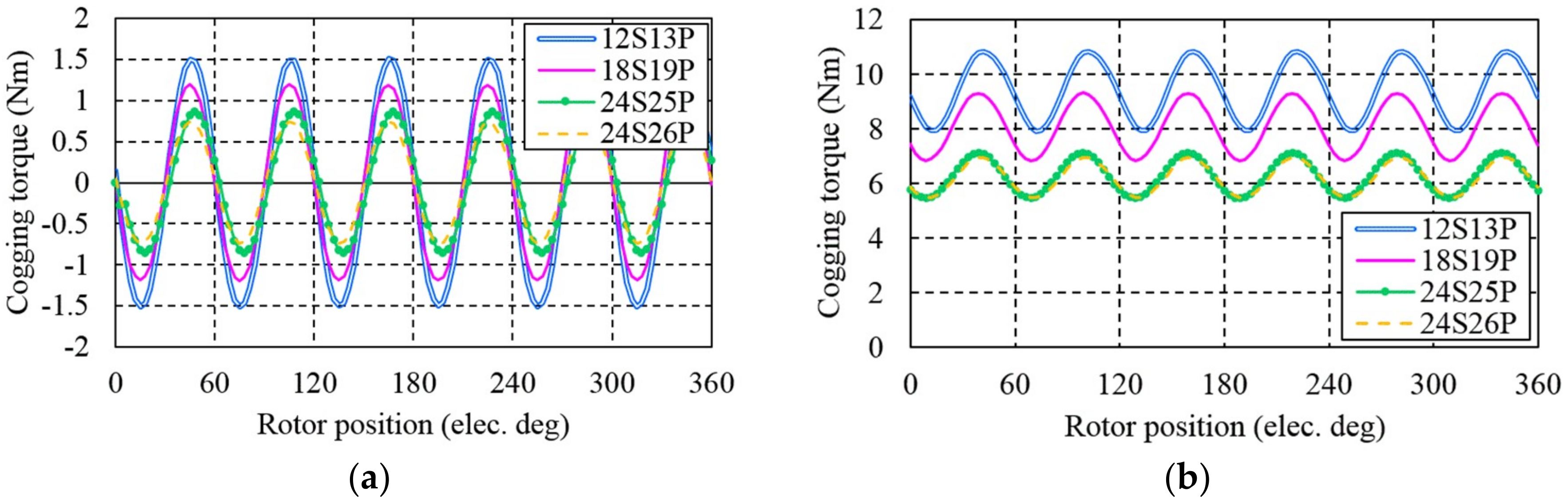
3.1. Cogging Torque and Torque

The conventional cogging torque period in mechanical degrees can be described as
θ c = 360 L C M ( N s , N r )
Here, θ c is the cogging torque period in mechanical degrees; N s and N r are the stator slots and rotor poles number, L C M ( N s , N r ) is the least common multiple of N s and N r [13].
This formula does not apply for the PGCC winding topologies because the stator configuration is different compared to the conventional machines. This is a result of the grouped stator poles. This modified stator configuration changes the periodicity of the stator slots and rotor poles interactions, consequently changing the period of the cogging torque. Thus, a different equation is developed, which can be written as follows:
θ c _ P G C C = 360 L C M ( N s , N r / n 1 )
Here, θ c _ P G C C is the cogging torque period of the PGCC winding topology in mechanical degrees. This always results in six periods of cogging torque in one period of electrical angle in every possible combination of three-phase PGCC winding machines.
The various torque performance of each machine analyzed by two-dimensional (2D) FEM are shown in Figure 3 and Table 3.
Figure 3a proves the aforementioned statement regarding the periodicity of the cogging torque. We found that the amplitude of the cogging torque decreases as the number of poles increases owing to the decreased magnet thickness, and more dispersed magnetic force. The average torque was also reduced owing to an increase in leakage flux, accompanied with the increased slot and pole number [17]. A small reduction in the average torque was due to the thinner magnets with the higher number of slots, allowing the magnets to operate at lower magnet operating points. Even though the 12S13P FSPMM exhibited the highest cogging torque and torque ripple, it demonstrated the top average torque value. Consequently, the 12S13P PGCC FSPMM was selected.

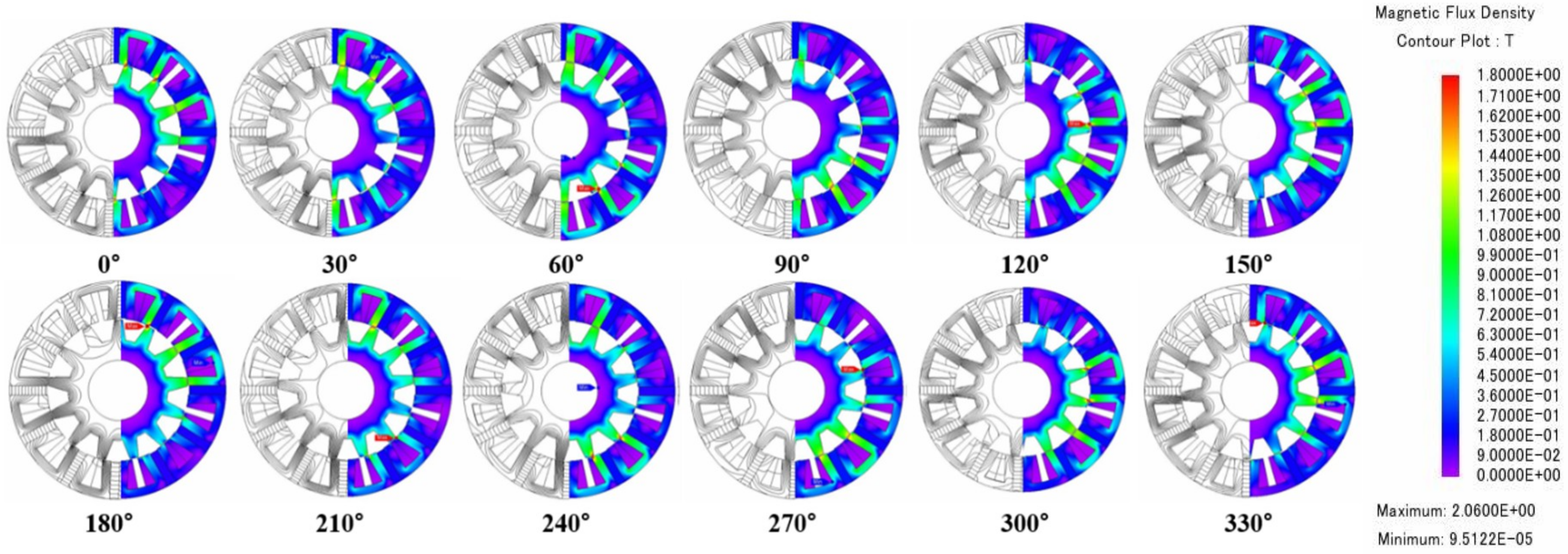
3.2. Flux Line and Flux Density

FEM analysis results in load condition which shows the flux lines and flux density which were depicted in Figure 4. A total of 12 plots were shown with the interval of 30 degrees in electrical angle. Flux lines show the ‘flux switching’ in the rotor poles, as the name of the topology indicates. Flux density contour plots show little saturation at the tip of the rotor poles due to the cogwheel-like rotor structure. Good flux density distribution was shown on the other parts of the machine.

4. Optimization for Cogging Torque Reduction

4.1. Cogging Torque Reduction Technique
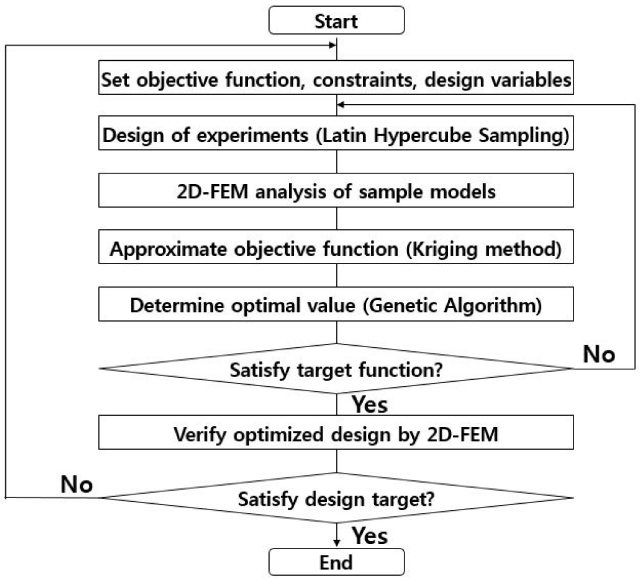
To decrease the cogging torque of the 12S13P FSPMM, a technique was proposed. The primary idea of the method is to reduce the interaction of the rotor pole and stator slot to reduce cogging torque, while minimizing the average torque reduction. By introducing round-shaped fillets to the rotor pole tip and adjusting the stator iron pole thickness, the idea was realized. By introducing a pole-arc R to the rotor pole, as shown in Figure 5, the magnetic force of the stator magnets that attracts the rotor iron poles to cause cogging torque was decreased. The airgap interacting surface area of the rotor pole, and the distance between the stator tooth and the rotor pole was changed to affect the cogging torque and the average torque.
To utilize the best magnet thickness and stator iron pole to achieve the lowest cogging torque with the highest average torque, the tooth width L was adjusted, as shown in Figure 5. To maintain the balanced back-EMF and PGCC winding effect, the base line was fixed as the center of the tooth width L, as depicted in Figure 5. The magnet thickness determined the magnet operating point, and thus determined the total magnetic flux of the machine. The stator iron pole thickness determined the air-gap interacting surface area of the stator, and thus the magnetic force and air-gap flux density. These facts support that the two parameters, R and L, affect the cogging torque and average torque. The two parameters R and L were optimized to elicit the best performance for the proposed PGCC FSPMM.

4.2. Optimization

An optimization process to optimize three parameters simultaneously within a short time was utilized. The total optimization process is depicted as a flowchart in Figure 6 [18]. The rotor pole-arc R and stator tooth width L were chosen as design variables for optimization. A design of the experiment was constructed using Latin hypercube sampling. A 2D-FEM analysis was conducted for all the sample models. For the approximation of the objective function from the analysis results of the sample models, the Kriging method was utilized. Next, to discover the optimal values, genetic algorithm was adopted. The process was repeated by a feedback loop until the target value was achieved.

4.3. Objective Function, Constraints, and Design Variables

The objective function was set to minimize the cogging torque. The constraints of the optimization are indicated as below:
  • Objective function
Minimize cogging torque
  • Constraint
Average torque > 8.2 Nm, Torque ripple < 10%, Slot fill factor < 45%
Cogging torque, which was an objective function, was analyzed on a no-load condition with a speed of 1 RPM. This was to analyze the cogging torque caused by the magnet without input current.
Slot fill factor was set to be lower than 45% to maintain the current density, while the manufacturing possibility was guaranteed.
The range of the rotor pole-arc R was selected by considering the rotor pole size and its effect on the torque performance. The stator tooth width L was adjusted based on the distance from the base line in the middle of the stator tooth iron part. The range of L was selected considering the slot opening and magnet thickness. The selected design variable ranges are as follows:
  • Design variables
1 < Rotor pole-arc R < 2.5
3 < Stator tooth width L < 7

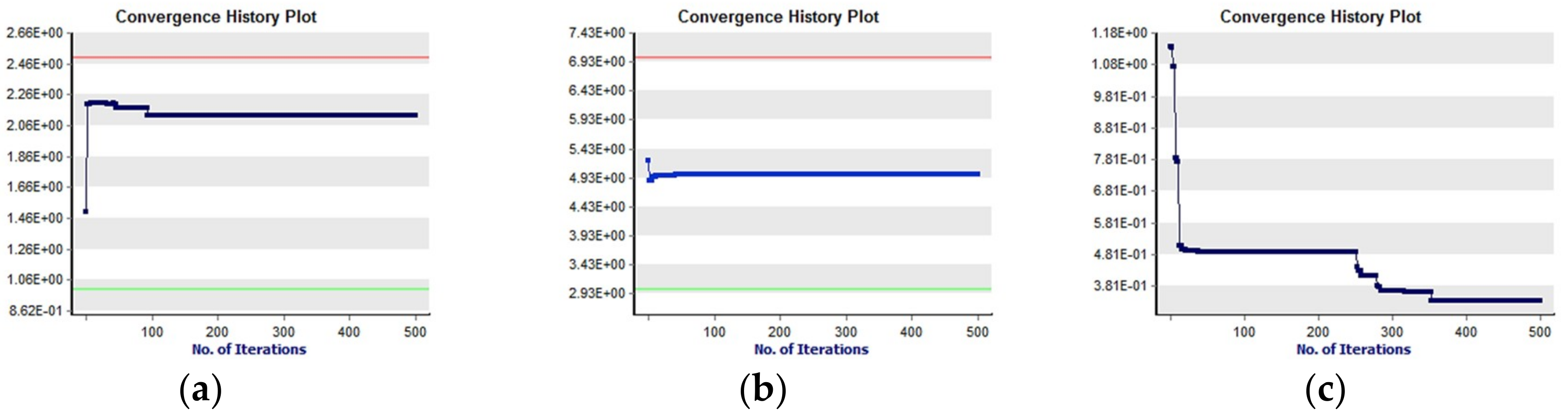
4.4. Optimization Results

The convergence plot of the design variables R, L and the cogging torque are depicted in Figure 7. Table 4 describes the converged optimal design variables.
As shown in Figure 7, convergence was achieved within 500 iterations. Owing to the constraints, the cogging torque was converged at no less than 0.33.
The torque performances of the initial model and the optimized model are shown in Figure 8 and Table 5.
The optimized design showed 89% cogging torque reduction, and 72.4% torque ripple reduction with only 7% of average torque sacrifice.
Performance losses due to the end effects were often considered in the FSPMM [19]. The end effect was caused by magnet flux leakage in the shaft-axis direction. The effect increases as the ratio of stack length to the machine’s outer diameter decreases [20]. The 3D-FEM analysis that can also analyze the end effect was performed on the final optimized model to reveal the performance loss due to the end effect. The 3D-FEM analysis result showed 3% less back-EMF due to the end effect. The end effect decreased the performance by 3% in this machine and is an acceptable performance loss based on previous studies that discussed the end effect [19,20,21].

5. Prototype Experiment and Discussion

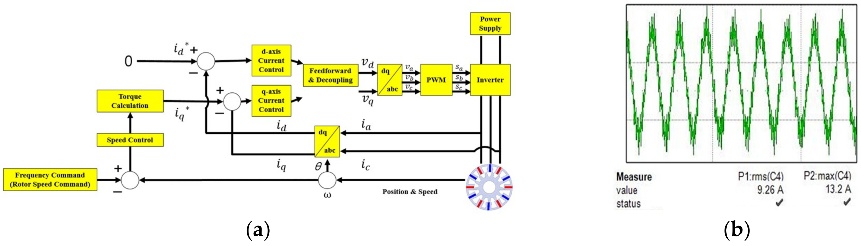
5.1. Experimental Setup and Control Method

Experiments were performed on the manufactured prototype of the final optimized 12S13P PGCC FSPMM. The stator, rotor lamination segment, and experimental setup are shown in Figure 9. Figure 9a,b shows the manufactured proposed machine which was optimized. Figure 9c shows the experimental setup. A control setup on the left side was composed with the commercial drive, a laptop to input the specific codes, and a torque indicator. On the top side of the figure, the load motor, torque sensor and prototype were connected mechanically for the load experiment. An oscilloscope to measure the various performance of the prototype machine was positioned at the right side of the figure.
To control the prototype machine, a commercial AC inverter drive model YASKAWA inverter A1000 was used. As the prototype machine consisted sinusoidal back-EMF, a sinusoidal current was fed with the same phase to the back-EMF to produce the positive sum of resultant torque. To feed a sinusoidal waveform current to the prototype machine, a pulse-width modulation (PWM) method which generates the sinusoidal waveform by switching on and off between the supply and load at fast rate was used. A specific PWM method called space vector modulation, which generates multi-phase sinusoidal, was utilized with more than 10 kHz of switching frequency. Maximum torque per ampere (MTPA) control was used to reach the target torque and speed. Control configuration of the prototype and the generated sinusoidal waveform current was shown in Figure 10.

5.2. Experimental Results and Discussion

Back-EMF, cogging torque and torque were measured on the prototype. The 2D-, 3D-FEM analysis results, and the measured data of the prototype are shown in Figure 11 and Table 6. Mainly due to the manufacturing tolerance, the experimental results of the back-EMF showed lower values than the FEM analysis results. Especially, the waveform of the FEM analysis results showed some harmonic components where it was reduced in the experimental results.
The measurement of the cogging torque was done with a different setup from the average torque measurement system. The prototype was rotated without the load at the speed of 1 RPM. The torque sensor of the cogging torque measuring system was able to detect the force due to the magnets in the machine. The measured cogging torque exhibits additional harmonics, mainly owing to the eccentricity. Also, harmonics in the measured cogging torque were exhibited subordinately owing to the mechanical tolerances in manufacturing and the assembly difficulties in practice. Another factor was the difficulty of measuring the precise cogging torque since the value was too low. However, the experiment results were reasonable as the cogging torque period was the same and peak values were similar.
The experimental results of the torque exhibited lower values than FEM analysis results, due to the difference of the back-EMF values. Generally, the experimental results showed good agreement with the values of the 3D-FEM analysis, allowing minor errors caused by the manufacturing tolerance and measuring limit [6,22,23].

6. Conclusions

A novel FSPMM for high torque density with the aid of PGCC winding that adopted cogging torque reduction was proposed. The PGCC winding configuration was used to increase the torque density. Stator slot and rotor pole combinations were studied to obtain the maximum torque density, and the 12S13P combination was chosen from the FEM analysis results. The rotor pole-arc R and stator tooth width L optimization was performed to minimize the cogging torque while minimizing the torque reduction. Our results showed that the optimized model had significantly reduced the cogging torque and torque ripple with little sacrifice on the torque density. The 3D-FEM analysis results were shown to consider the end effect. Finally, the prototype of the optimized machine was manufactured to compare the 3D-FEM analysis and the experimental results. The experimental results exhibited good agreement with the analysis results considering the small manufacturing tolerance and eccentricity. However, the unbalanced structure of the proposed machine caused vibration issues due to large net transverse forces and flexural vibrations. These will be solved in further study.

Author Contributions

J.-W.K. designed the basic model, performed the optimization, analyzed and compared the results, and wrote this paper; B.I.K. supervised the research throughout. Writing—review & editing, B.-I.K., J.-h.L. and W.Z.

Funding

This research received no external funding.

Acknowledgments

This work was supported in part by the Human Resources Program in Energy Technology of the Korea Institute of Energy Technology Evaluation and Planning (KETEP), granted financial resource from the Ministry of Trade, Industry & Energy, Republic of Korea (No. 20174030201780), and in part by the BK21PLUS Program through the National Research Foundation of Korea within the Ministry of Education.

Conflicts of Interest

The authors declare no conflict of interest.

References

  1. Zhu, Z.Q. Switched Flux Permanent Magnet Machines—Innovation Continues. In Proceedings of the International Conference on Electrical Machines and Systems, Beijing, China, 20–23 August 2011; pp. 1–10. [Google Scholar]
  2. Zhao, W.; Lipo, T.A.; Kwon, B.I. A Novel Dual-Rotor, Axial Field, Fault-Tolerant Flux-Switching Permanent Magnet Machine with High-Torque Performance. IEEE Trans. Magn. 2015, 51, 1–4. [Google Scholar] [CrossRef]
  3. Liu, X.; Wu, D.; Zhu, Z.Q.; Pride, A.; Deodhar, R.P.; Sasaki, T. Efficiency Improvement of Switched Flux PM Memory Machine Over Interior PM Machine for EV/HEV Applications. IEEE Trans. Magn. 2014, 50, 1–4. [Google Scholar] [CrossRef]
  4. Li, Y.; Bobba, D.; Sarlioglu, B. A Novel 6/4 Flux-Switching Permanent Magnet Machine Designed for High-Speed Operations. IEEE Trans. Magn. 2016, 52, 1–9. [Google Scholar] [CrossRef]
  5. Zhu, X.; Shu, Z.; Quan, L.; Xiang, Z.; Pan, X. Multi-Objective Optimization of an Outer-Rotor V-Shaped Permanent Magnet Flux Switching Motor Based on Multi-Level Design Method. IEEE Trans. Magn. 2016, 52, 1–8. [Google Scholar] [CrossRef]
  6. Zhu, X.; Xiang, Z.; Zhang, C.; Quan, L.; Du, Y.; Gu, W. Co-Reduction of Torque Ripple for Outer Rotor Flux-Switching PM Motor Using Systematic Multi-Level Design and Control Schemes. IEEE Trans. Ind. Electron. 2017, 64, 1102–1112. [Google Scholar] [CrossRef]
  7. Zhao, J.; Zheng, Y.; Zhu, C.; Liu, X.; Li, B. A Novel Modular-Stator Outer-Rotor Flux-Switching Permanent-Magnet Motor. Energies 2017, 10, 937. [Google Scholar] [CrossRef]
  8. Su, P.; Hua, W.; Wu, Z.; Han, P.; Cheng, M. Analysis of the Operation Principle for Rotor-Permanent-Magnet Flux-Switching Machines. IEEE Trans. Ind. Electron. 2018, 65, 1062–1073. [Google Scholar] [CrossRef]
  9. Cao, R.; Jin, Y.; Lu, M.; Zhang, Z. Quantitative Comparison of Linear Flux-Switching Permanent Magnet Motor with Linear Induction Motor for Electromagnetic Launch System. IEEE Trans. Ind. Electron. 2018, 65, 7569–7578. [Google Scholar] [CrossRef]
  10. Bobba, D.; Li, Y.; Sarlioglu, B. Harmonic Analysis of Low-Stator-Slot and Rotor-Pole Combination FSPM Machine Topology for High Speed. IEEE Trans. Magn. 2015, 51, 1–4. [Google Scholar] [CrossRef]
  11. Hua, W.; Cheng, M.; Zhu, Z.Q.; Zhao, W.; Kong, X. Comparison of electromagnetic performance of brushless motors having magnets in stator and rotor. J. Appl. Phys. 2008, 103, 07F124. [Google Scholar] [CrossRef]
  12. Wang, D.; Wang, X.; Jung, S.Y. Reduction on Cogging Torque in Flux-Switching Permanent Magnet Machine by Teeth Notching Schemes. IEEE Trans. Magn. 2012, 48, 4228–4231. [Google Scholar] [CrossRef]
  13. Sikder, C.; Husain, I.; Ouyang, W. Cogging Torque Reduction in Flux-Switching Permanent-Magnet Machines by Rotor Pole Shaping. IEEE Trans. Ind. Appl. 2015, 51, 3609–3619. [Google Scholar] [CrossRef]
  14. Hao, L.; Lin, M.; Xu, D.; Zhang, W. Cogging Torque Reduction of Axial Field Flux-Switching Permanent Magnet Machine by Adding Magnetic Bridge in Stator Tooth. IEEE Tran. Appl. Supercond. 2014, 24, 1–5. [Google Scholar] [CrossRef]
  15. Jia, H.; Cheng, M.; Hua, W.; Zhao, W.; Li, W. Torque Ripple Suppression in Flux-Switching PM Motor by Harmonic Current Injection Based on Voltage Space-Vector Modulation. IEEE Trans. Magn. 2010, 46, 1527–1530. [Google Scholar] [CrossRef]
  16. Kim, J.M.; Yoon, M.H.; Hong, J.P.; Kim, S.I. Analysis of Cogging Torque Caused by Manufacturing Tolerances of Surface-mounted Permanent Magnet Synchronous Motor for Electric Power Steering. IET Electr. Power Appl. 2016, 10, 691–696. [Google Scholar] [CrossRef]
  17. Thomas, A.; Zhu, Z.Q.; Jewell, G.W.; Howe, D. Flux-switching PM Brushless Machines with Alternative stator and rotor pole combinations. In Proceedings of the IEEE ICEMS, Wuhan, China, 17–20 October 2008; pp. 2986–2991. [Google Scholar]
  18. Yoon, K.Y.; Kwon, B.I. Optimal Design of a New Interior Permanent Magnet Motor Using a Flared-Shape Arrangement of Ferrite Magnets. IEEE Trans. Magn. 2016, 52, 1–4. [Google Scholar] [CrossRef]
  19. Al-Ani, M.M.J.; Zhu, Z.Q. Influence of End-effect on Torque-speed Characteristics of Various Switched Flux Permanent Magnet Machine Topologies. In Proceedings of the IEEE ICEMS, Hangzhou, China, 22–25 October 2014; pp. 2517–2523. [Google Scholar]
  20. Zhu, Z.Q.; Chen, J.T.; Pang, Y.; Howe, D.; Iwasaki, S.; Deodhar, R. Modeling of End-effect in Flux-switching Permanent Magnet Machines. In Proceedings of the IEEE ICEMS, Seoul, Korea, 8–11 October 2007; pp. 943–948. [Google Scholar]
  21. Mo, L.; Zhu, X.; Zhang, T.; Quan, L.; Wang, Y.; Huang, J. Temperature Rise Calculation of a Flux-Switching Permanent-Magnet Double-Rotor Machine Using Electromagnetic-Thermal Coupling Analysis. IEEE Trans. Magn. 2018, 54, 1–4. [Google Scholar] [CrossRef]
  22. Zhao, W.; Chen, D.; Lipo, T.A.; Kwon, B.I. Dual Airgap Stator- and Rotor-Permanent Magnet Machines with Spoke-Type Configurations Using Phase-Group Concentrated Coil Windings. IEEE Tran. Ind. Appl. 2017, 53, 3327–3335. [Google Scholar] [CrossRef]
  23. Zhu, X.; Hua, W.; Wu, Z.; Huang, W.; Zhang, H.; Cheng, M. Analytical Approach for Cogging Torque Reduction in Flux-Switching Permanent Magnet Machines Based on Magnetomotive Force-Permeance Model. IEEE Trans. Ind. Electron. 2018, 65, 1965–1979. [Google Scholar] [CrossRef]
Figure 1. Topology of 12S13P FSPMM with PGCC windings.
Energies 11 02758 g001
Figure 2. 12S13P PGCC winding: (a) winding configuration, (b) resultant EMF vector.
Energies 11 02758 g002
Figure 3. Analysis results of PGCC FSPMM with different combinations: (a) cogging torque, (b) torque.
Energies 11 02758 g003
Figure 4. Flux lines and flux densities of the 12S13P PGCC FSPMM.
Energies 11 02758 g004
Figure 5. Selected design variables for optimization.
Energies 11 02758 g005
Figure 6. Optimization process flowchart.
Energies 11 02758 g006
Figure 7. Convergence plot: (a) rotor pole-arc R, (b) stator tooth width L, (c) cogging torque.
Energies 11 02758 g007
Figure 8. Performance comparison of initial and optimized model: (a) cogging torque, (b) output torque.
Energies 11 02758 g008
Figure 9. Manufactured prototype and experimental setup: (a) stator, (b) rotor lamination segment, (c) experimental setup.
Energies 11 02758 g009
Figure 10. Control method: (a) prototype control configuration, (b) generated sinusoidal waveform current.
Energies 11 02758 g010
Figure 11. 3D-FEM analysis and experimental data comparison: (a) back-EMF, (b) cogging torque, (c) torque.
Energies 11 02758 g011
Table 1. PGCC FSPM combinations.
n 1 n 2 Combinations
2212S13P
3218S19P
4224S25P
2424S26P
Table 2. Specifications of the analyzed machines.
ItemUnitPGCC FSPMM
Outer diametermm135
Inner diametermm85
Axial lengthmm85
Air-gap radial thicknessmm0.5
Phase coil turns-96
Magnet grade-Ferrite/0.43 T
Steel sheet-50H440
Rated currentA13
Current density (RMS value)Arms/mm24
Slot area (small slot)mm2153.1
Slot fill factor (small slot)%35
Rated speedRPM1500
Rated frequencyHz325
Rated torqueNm8.2
Table 3. Analysis results of the various combinations of PGCC FSPMM.
ItemUnit12S13P18S19P24S25P24S26P
Cogging torqueNm3.012.031.461.26
Torque ripple%33.3730.6626.4723.61
Average torqueNm9.028.026.676.60
Table 4. Initial and optimized design variables.
ItemUnitInitialOptimized
Rmm1.52.08
Lmm5.325
Table 5. FEM analysis results.
ItemUnitInitialOptimized (2D-FEM)Optimized (3D-FEM)
Back-EMFVrms52.8147.3445.76
Cogging torqueNm3.010.330.32
Torque ripple%33.379.209.12
Average torqueNm9.028.348.12
Table 6. 2D, 3D-FEM analysis, experiment data comparison.
ItemUnit2D-FEM3D-FEMExperiment
Phase BEMFVrms47.3445.7644.6
Cogging torqueNm0.330.330.39
Rated torqueNm8.348.127.97

