Article

Laboratory Investigation on Hydrodynamic Performance of an Innovative Aeration Device with a Wave-Driven Heaving Buoy

1
Engineering College, Ocean University of China, Qingdao, 266100, China
2
Shandong Province Key Laboratory of Ocean Engineering, Ocean University of China, Qingdao 266100, China
3
China Communications Planning and Design Institute for Water Transportation LTD, NO.28 Guozijian St., Beijing 100007, China
*
Author to whom correspondence should be addressed.
Energies 2018, 11(12), 3262; https://doi.org/10.3390/en11123262
Submission received: 8 October 2018 / Revised: 10 November 2018 / Accepted: 16 November 2018 / Published: 23 November 2018
(This article belongs to the Section A: Sustainable Energy)

Abstract

:
Coastal seawater quality is of significance for the environment, ecology and fisheries. In recent years, the hypoxia or anoxia problems of bottom seawater aggravated due mainly to the seawater stratification and eutrophication. This paper addresses an innovative aeration device with a wave-driven heaving buoy to enhance the dissolved oxygen concentration for bottom water. A series of physical experiments was conducted to investigate its hydrodynamic performance and air flow rate. The response amplitude of heaving components and the average value of air flow rate were examined with the related parameters, including incident wave height, incident wave steepness and aeration depth. It was found that with increasing incident wave height, the average heaving displacement and the average air flow rate increase respectively. With the increase of incident wave steepness, the relative value of average heaving displacement increases obviously for high wave period scenarios, it increases slightly for small wave period scenarios in comparison and the relative value of air flow rate increases evidently. With the increase of aeration depth, the average heaving displacement and the average air flow rate decrease respectively. With the increase of relative aeration depth, the relative value of average heaving displacement and the relative value of air flow rate decrease respectively. In addition, the dimensional analysis and the least squares methods were used to obtain the prediction formulas for the average heaving displacement and the average air flow rate, and they agreed well with the related experimental data.

1. Introduction

Dissolved oxygen concentration (DOC) is one of the important indicators of seawater quality. The hypoxia (DOC< 2.0 mg/L or approximately 30% saturation) contributed a great deal to the lower growth and reproduction capability of aquatic organisms and even their death in water. In addition, it caused the deterioration of water environment and ecology to a great extent [1,2]. In recent years, a great deal of nitrogen and phosphorus nutrients are released into rivers and coastal water, and the eutrophication aggravated as a result. Furthermore, the seawater stratification occurred seriously due mainly to the water temperature increment for global climate warming trend. Consequently, more than 400 hypoxia zones had been reported globally and a total area of more than 245,000 square kilometers was affected obviously including Baltic, Kattegat, Black Sea, Gulf of Mexico and East China Sea [2]. Concerning the Changjiang Estuary in summer 2009, a severe hypoxia lasted for more than a half month and the minimum DOC was measured down to 0.17 mg/L for bottom water [3]. It is well-known that dissolved oxygen originates from the photosynthesis of aquatic plants and the atmosphere in natural ocean. A great deal of contributions has been paid on the investigation of aquatic plants photosynthesis and oxygen release mechanism and they were determined mainly by the sunlight frequency, sunlight intensity, water temperature and carbon dioxide concentration. Concerning the oxygen transfer characteristic from atmosphere to seawater, wave, current, seawater stratification, wind direction and swell regime and so forth, play significant roles in the DOC increase of coastal zone, and the various formulas of oxygen transfer coefficient were conducted considering the effects of wind and wave parameters such as wave slope, drag force coefficient and wave height and so forth [4,5,6,7]. In particular, Mahrt et al. [8] reported the drag coefficient dependence on wind fetch conditions by using the measured data of field work. Fairall et al. [9] examined the shallow, stable boundary layer characteristics in the cool coastal water of Maine Gulf, between Cape Cod and Nova Scotia. Vickers and Mahrt [10] analyzed the sea-surface roughness lengths for momentum and sensible heat using the observed data of midlatitude coastal-zone. Grachev et al. [11] described the air-sea turbulent fluxes of coastal waters in Mexico Gulf. Grachev et al. [12] explored the air-sea/land coupling on coastal environments near the town of Duck, North Carolina and the inherent heterogeneity of coastal land surfaces, complex topography and irregular coastline shapes was taken into account. Jiménez and Dudhia [13] addressed the aerodynamic roughness length formulation of shallow ocean waters in WRF models.
Due to the difficulty in controlling the natural wind and wave and so forth, considerable attention has been devoted to the artificial technologies to enhance DOC in ocean bottom water, such as the exchange between bottom hypoxia water and oxygen-rich surface water, as well as the bubbly aeration in bottom hypoxia water. Concerning the vertical water exchange, Stommel et al. [14] proposed a perpetual salt fountain concept to pump up the nutrient rich deep water to the surface for fishing and farming application by long pipes for the first time. Liu et al. [15] evaluated the hydrodynamic performance of a wave-driven artificial upwelling device in the Hawaiian ocean numerically. In terms of the South China Sea, Fan et al. [16] numerically examined the nutrient transport for deep ocean water plume by using an artificial upwelling device. Subsequently, Fan et al. [17] explored the hydrodynamic performance of a wave pump in regular waves experimentally and theoretically. Antonini et al. [18,19] addressed the use of a new floating device to increase DOC in bottom water experimentally and numerically, and its dynamic response and pumping capacity were assessed with the wave parameters. With respect to the bubbly aeration technology to improve DOC in hypoxia water, Endo et al. [20] developed a micro bubble aerobic system for increasing oxygen in aquaculture economically and efficiently. Cong et al. [21] used a hydraulic gun to aerate the air for bottom water in Fenhe reservoir in winter. Zhou et al. [22] investigated the micro bubble aeration capacity in a wastewater treatment plant. Yin et al. [23] assessed the oxygen transfer characteristic of air injection in a horizontal pipe flow numerically.
The efforts aforementioned are essential for assessing DOC variation to protect water environment and quality. The main objective of our study is to present an innovative aeration device with a wave-driven heaving buoy to produce the air bubbles as well as enhance the DOC for dealing with the hypoxia or anoxia problem in deep water. The device is driven by the natural waves, rather than the electricity or fuel. Consequently, it has the economical and environmentally friendly advantages in theory. In our paper, a series of experiments was conducted to examine the hydrodynamic and aeration characteristics with regular waves experimentally. The remainder of the paper is organized as follows, Section 2 concerns the experiments, including the device structure and working principle as well as experimental setup and scenarios. Section 3 describes the experimental results. In addition, the heaving motion and air flow rate were explored with various wave parameters. Section 4 draws a brief conclusion and the research limitation is addressed.

2. Experiments

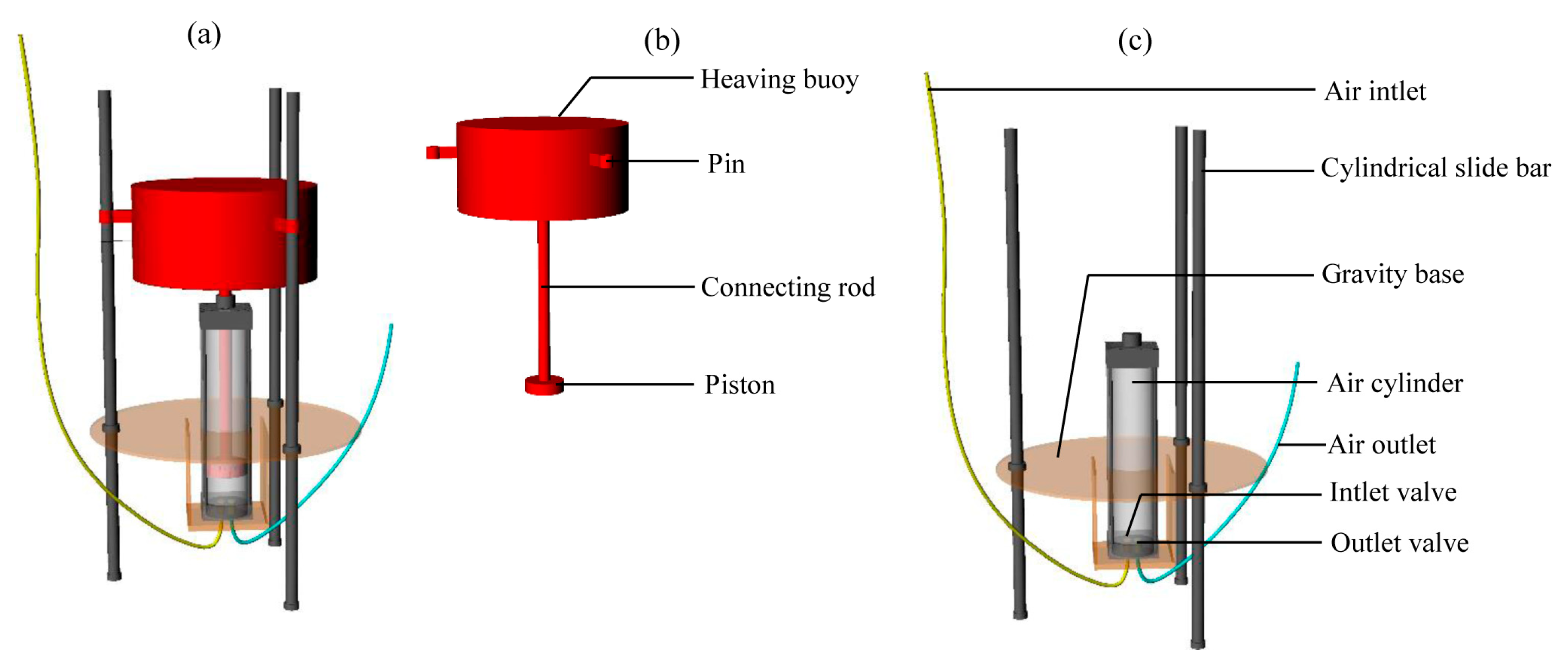
2.1. Device Structure and Physical Principle

The capability of experimental facilities and the required wave parameters were taken into account, and a geometric similarity scale of 1:4 was used for the experiments to reproduce the processes in prototype. Figure 1 shows the device sketch and its total height is 1.40 m. It consists of two parts, one is the heaving components and the other is the immovable components. The heaving components consist of a circular hollow cylinder for 0.45 m in diameter and 0.20 m in height as a heaving buoy to absorb the wave energy, a piston to suck air from the atmosphere or extrude air from the air cylinder for 0.12 m in diameter, 0.50 m in height and the cross section area A = 0.0113 m2, a connecting rod for 0.02 m in diameter and 0.50 m in height to connect the buoy and the piston, and three pins were fixed at the buoy outside to ensure its heaving motion along slide bars. The hollow cylinder mass was m = 18.5 kg, its volume was 0.03179 m3 and its density was 581.9 kg/m3. In comparison, the immovable components consist of a circular gravity base for 0.60 m in diameter and 0.01 m in height to assure the immovable component stability with the wave effect, three circular slide bars (0.02 m in diameter and 1.40 m in height) with guide rails ensure the heaving motion of buoy smoothly. An air cylinder for 0.12 m in inner diameter and 0.45 m in height was used to store the outside air. At its bottom, two circular holes were open with 0.01 m diameter, the one connected an air inlet tube with 0.01 m diameter through a one-way inlet valve to suck the outside air and the other connected an air outlet tube with 0.01 m diameter through a one-way outlet valve to release the air into deep hypoxia zone. Particular attention should be paid on the piston diameter equal to the inner diameter of air cylinder as possible. Generally, an oversize piston results into an excessive friction with the inner wall of air cylinder as well as reducing the air aeration efficiency as a result and even the unworkable result. On the contrary, an undersized piston causes the excessive gap between piston and inner wall of air cylinder, and a great deal of air and water moves through it to decrease the aeration and DOC enhancement efficiency.
Its working principle is rather simple. When the wave surface ascends, the heaving components go upward along the three slide bars with the wave excitation force effect. The pressure decreases inside the air cylinder and the outside air was sucked into the air cylinder through the inlet tube and inlet valve because of the pressure difference. When the wave surface descends, the heaving components go downward along the three slide bars due mainly to the gravity, the pressure increases inside the air cylinder, the inside air was pressed into the hypoxia deep water through outlet tube and outlet valve, and an air bubbly jet occurs. Subsequently, the bubbles rise and oscillate with the coupling effect of jet momentum, buoyancy and wave. Finally, the bubbles escape from the wave surface and an obvious wave breaking phenomenon appears. Simultaneously, the oxygen transfers from air bubbles to surrounding hypoxia water to improve DOC. It is expected that the device is helpful to counteract oxygen depletion for environmental protection engineering and the fish farming business and so forth, especially at the hypoxia water near bottom.

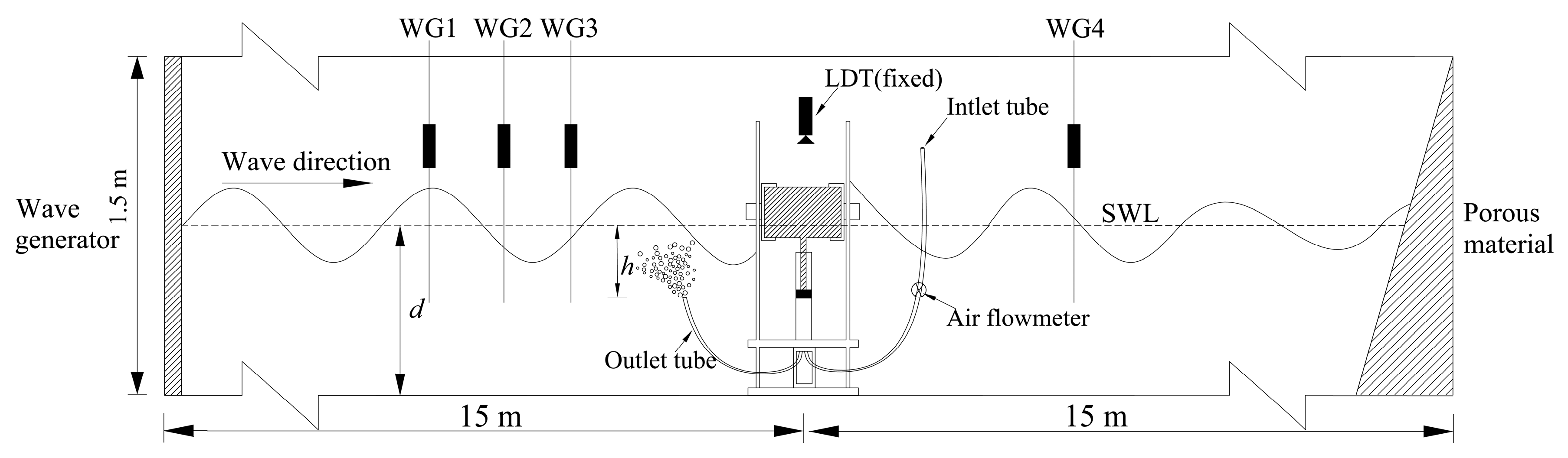
2.2. Experimental Setup, Scenarios and Procedure

To study its hydrodynamic characteristics and air aeration efficiency, a series of experiments was conducted in a wave flume (30.0 m in length, 3.0 m width and 1.5 m height) at the Key Laboratory of Ocean Engineering, Ocean university of China. Figure 2 shows the sketch of experimental setup. At one end of the wave flume, a piston-type wave paddle was used to generate the relatively simple regular waves in order to simplify our research and a great deal of porous material for 4 m length was installed at the other end to absorb the incident wave as well as avoid the unwanted wave reflection. The device was installed at 15.0 m location after the wave generator. Four wave gauges (WGs) with a sampling frequency of 50 Hz have been calibrated well by adjusting their positions, all the measured deviations were smaller than 0.5 mm and they were installed on the longitudinal axis of the flume, where WG1, WG2 and WG3 are before the device to roughly identify the incident and reflected waves by means of reflection analysis procedure [24] and WG4 was after the device to measure the wave transmission. A well-calibrated air flowmeter (SIARGO MF5700 type) linking the inlet tube with the accuracy of 0.01 L/min was used to measure the air flow process and the vertical displacement of the heaving buoy was measured by a laser displacement transducer with the accuracy of 0.001 m after using an on-line calibration approach reported by Xie et al. [25]. Time domain analysis of the incident wave has been used for every experiment.
The still water depth was kept as a constant value of d = 1.0 m for all experiments. The incident regular wave height H ranged from 0.18 m to 0.26 m (i.e., 0.72 m to 1.04 m for prototype) at a step of 0.02 m and the incident regular wave period T varied from 1.5 s to 2.7 s (i.e., 3.0 s to 5.4 s for prototype) at a step of 0.3 s, roughly matching the wave peak periods and significant heights at Bohai Sea and Yellow Sea (Yang et al. [26]). In addition, using the linear dispersion relationship, the incent wave length can be obtained as L = gT2tanh(kd)/2π, where k is the wave number and g is the gravity acceleration. All the relative water depth (d/L) values were greater than 0.05 and smaller than 0.5, which can be attributed to the finite water depth range [27], rather than a shallow-water wave or deep-water wave. In addition, the pressure at air outlet tube exit varied with its locations and it possibly plays a significant role in the heaving components motion and the air amount. Consequently, the submerged depth for the air outlet tube exit to still water level h was determined from 0.1 m to 0.5 m at a step of 0.1 m. 125 groups of experimental scenarios were determined with respect to the variation of aforementioned H, T and h. Note that all the experimental parameters were consistent well with the rules of model limits reported by Frostick et al. [28].
Before the experiment, the fresh tap water was pumped into the flume for d = 1.0 m. The wave generator started to generate the desired regular waves. The heaving components heaved along the slide bars. The outside air was sucked into the air cylinder and the inside air was pressed into local water intermittently. As a result, a periodic bubbly jet occurred and its period was consistent well with that of incident waves. The wave heights, the vertical displacement of heaving components and the air flow rates were measured for 100 T time range and their average values were used to further the hydrodynamic investigation.

3. Results

In this section, the incident wave parameter and aeration depth effects are investigated on the heaving displacement and air flow rate respectively.

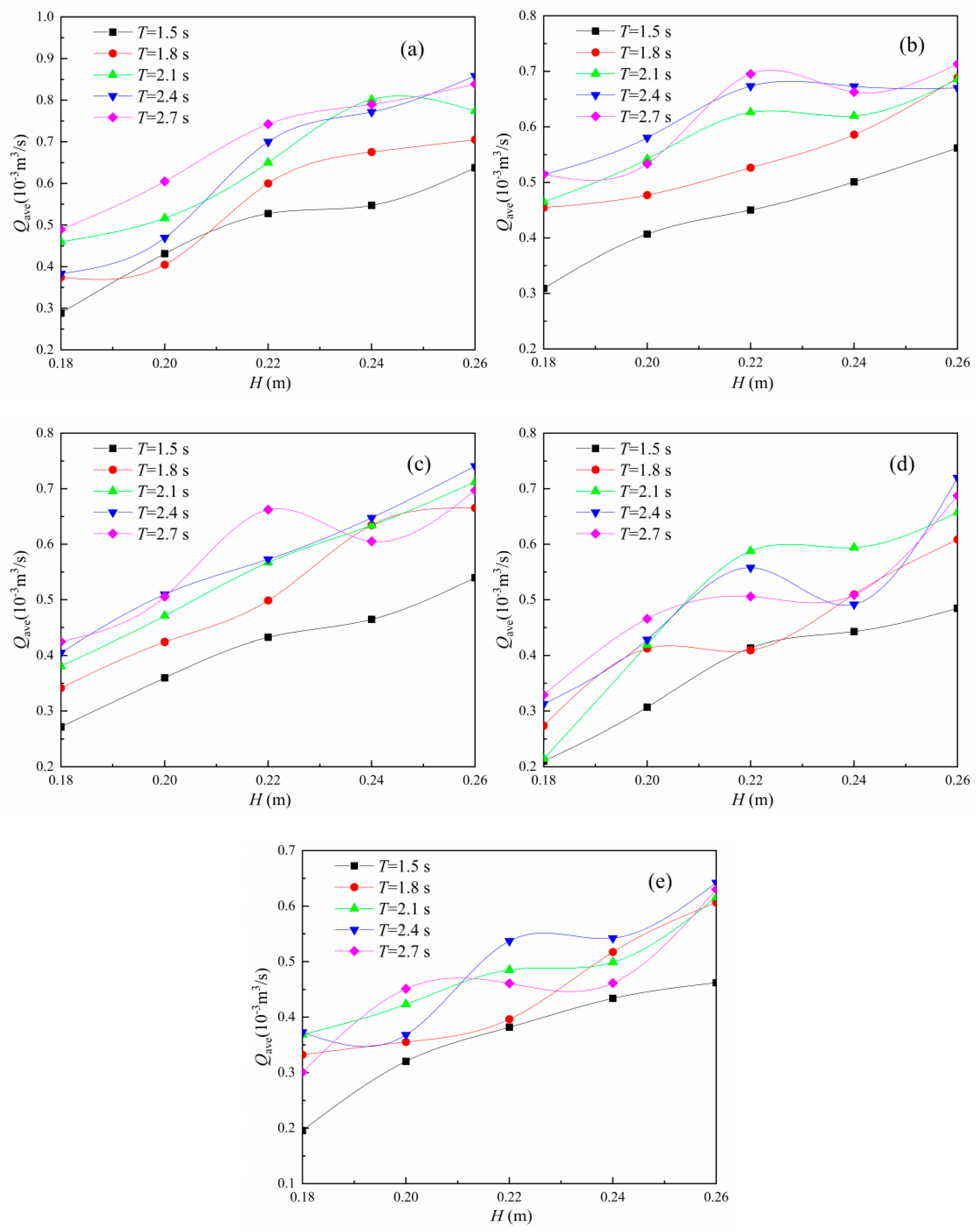
3.1. Incident Wave Parameters Effect

3.1.1. Incident Wave Height Effect

To investigate the incident wave height effect on heaving motion, Figure 3 shows the relationship between the average heaving displacement Zave and incident wave height H with various T and h, where Z ave = 1 n i = 1 n ( Z i , max Z i , min ) , Zi,max and Zi,min are the maximum and the minimum values of heaving displacement in ith period respectively, here n = 100. It was found that with increasing H, an approximate linear growth of Zave occurs approximately due to the increasing wave force on buoy. Additionally, Zave increases with increasing T to some extent and its increase amplitudes for small T scenarios were smaller than them for large T scenarios. With increasing T, the Zave difference for two adjacent T scenarios reduces gradually. In particular, the Zave values approached to each other for T = 2.4 s and T = 2.7 s scenarios, indicating that Zave is no longer sensitive to T for the larger wave period scenarios. A possible explanation is that for larger T scenarios with given H, the wave excited force on the heaving buoy and the vertical acceleration varied less within a unit time, and the heaving components were more prone to the slow motion in general. Simultaneously, the synchronous motion of heaving components matches well with the incident wave surface temporally and spatially. Consequently, Zave varied less with the T variation for larger T and given H scenarios. In addition, Zave decreases with increasing h to some extent as expected.
Figure 4 shows the average air flow rate Qave relationship with H, where Qave is obtained by averaging the air flow rate Q measured by the air flowmeter in 100T time range. It was illustrated that with increasing H and T, Qave increases in general. This is due mainly to the higher Zave for larger H and T scenarios as shown in Figure 3. Note that with increasing h, Qave decreases to some extent. It was expected that Qave shows a good consistence with Zave as shown in Figure 3 and Figure 4, and the main reason is that Qave can be theoretically determined as ZaveA/T without the consideration of air compressibility in air cylinder.

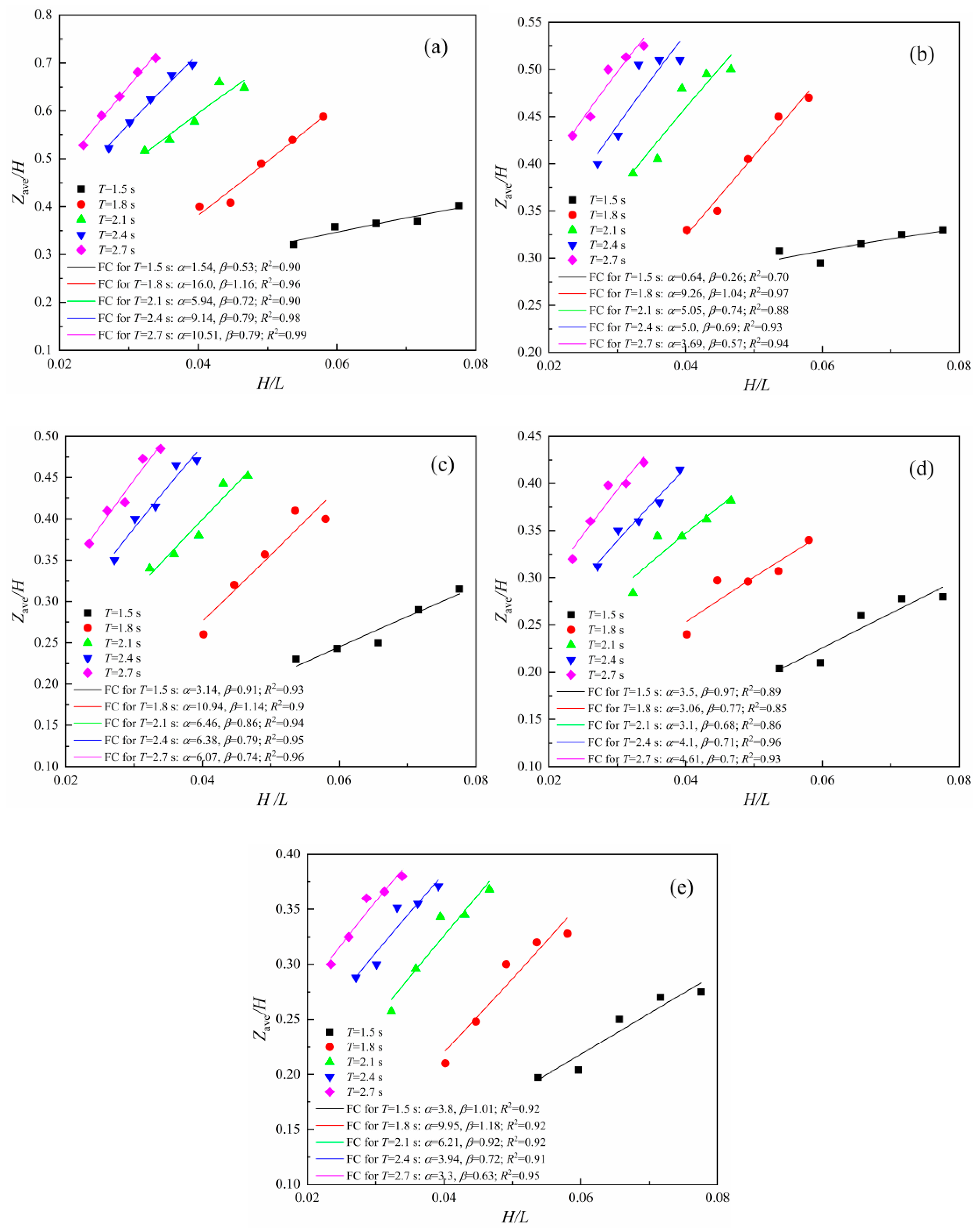
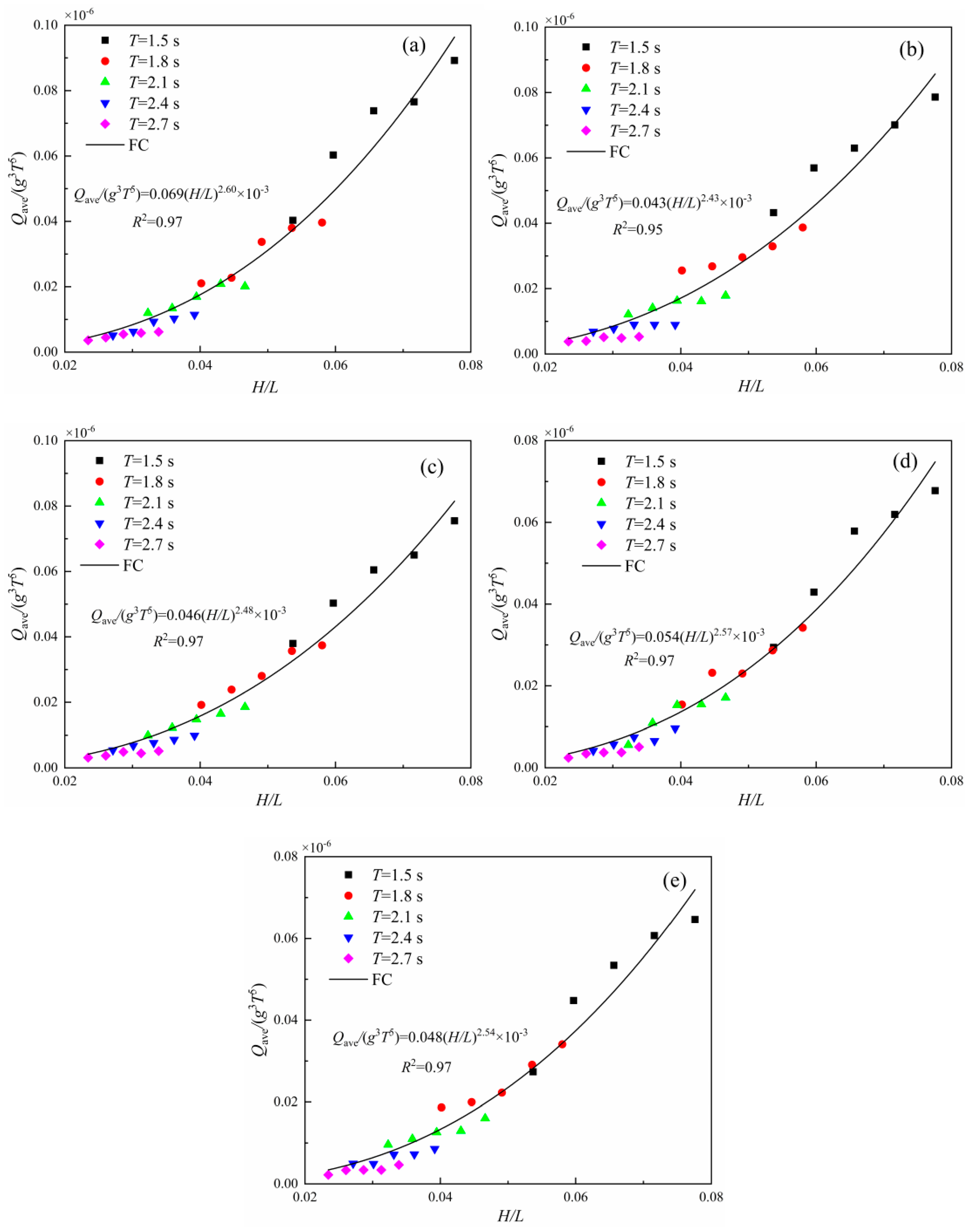
3.1.2. Incident Wave Steepness Effect

Figure 5 shows the relative value of average heaving displacement Zave/H relationship and the incident wave steepness H/L for different T and h scenarios, and their fitting curve (FC) was presented to further the exploration. It was observed that with increasing H/L, Zave/H increases in power function forms as Zave/H = α(H/L)β with high correlation coefficients, where α and β changed in terms of T variation respectively. Note that the fitting Zave/H increased slightly with increasing H/L for T = 1.5 s scenario; however, it increased obviously for T = 1.8 s, 2.1 s, 2.4 s to 2.7 s scenarios. As a result, T plays a complex role in Zave/H. With respect to the Zave/H relationship with h, it was illustrated that Zave/H decreases with increasing h, agreeing well with the Zave and Qave trends with h as shown in Figure 3 and Figure 4.
Figure 6 shows the relationship between the relative value of air flow rate Qave/g3T5 and the incident wave steepness H/L for different h and T scenarios. It was observed that Qave/g3T5 and its FC increased obviously with increasing H/L for various T and h scenarios. Note that Qave/g3T5 decreased with increasing h as shown in Figure 6a–e. In the case of h = 0.1 m scenarios, Qave/g3T5 ranges from 0.0036 to 0.089 as shown in Figure 6a. In comparison, it ranges from 0.0022 to 0.065 for h = 0.5 m scenarios as shown in Figure 6e. In addition, the FC obeys the power function Qave/g3T5 = α(H/L)β with high correlation coefficient larger than 0.95, illustrating the intrinsic relationship between Qave/g3T5 and H/L.

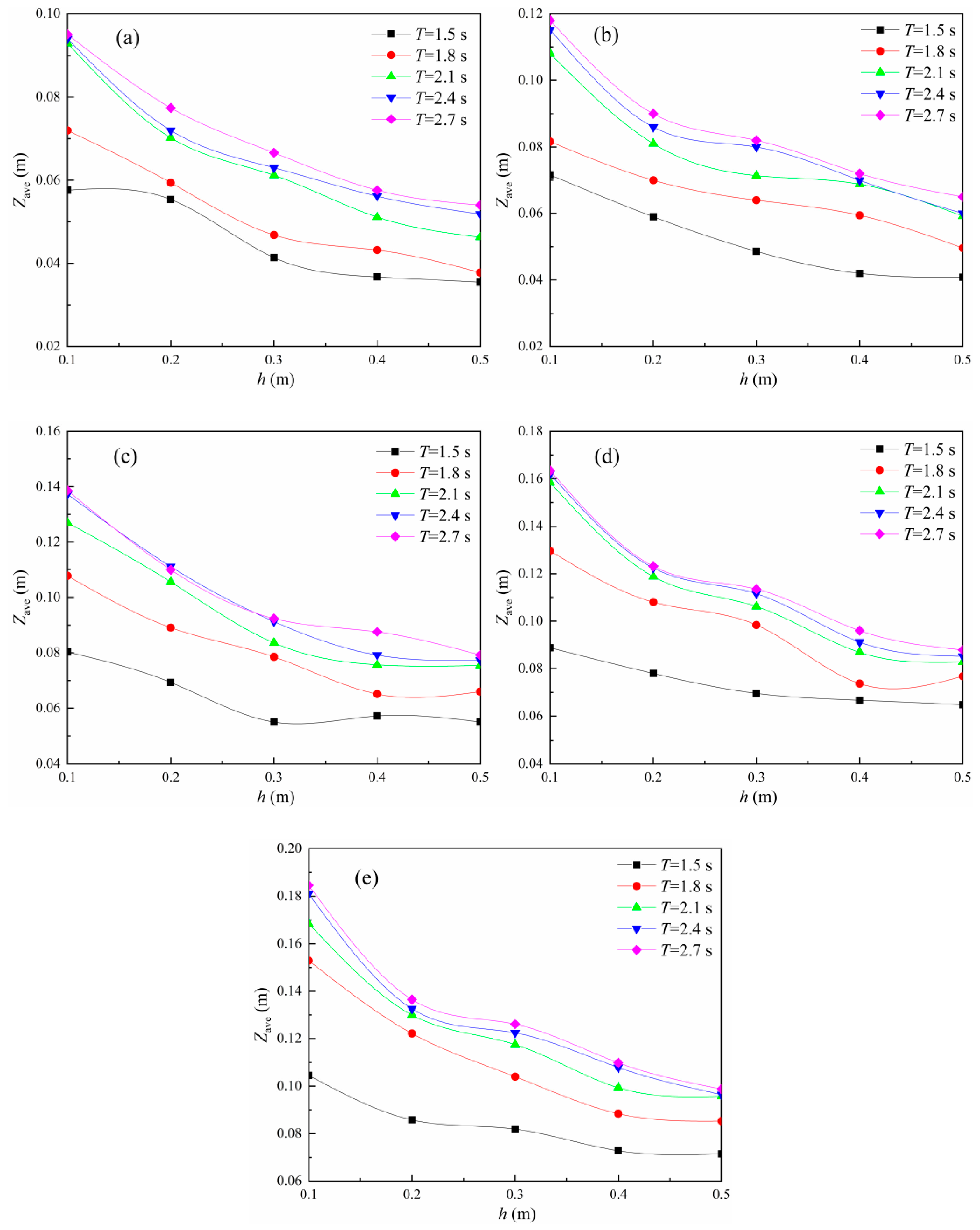
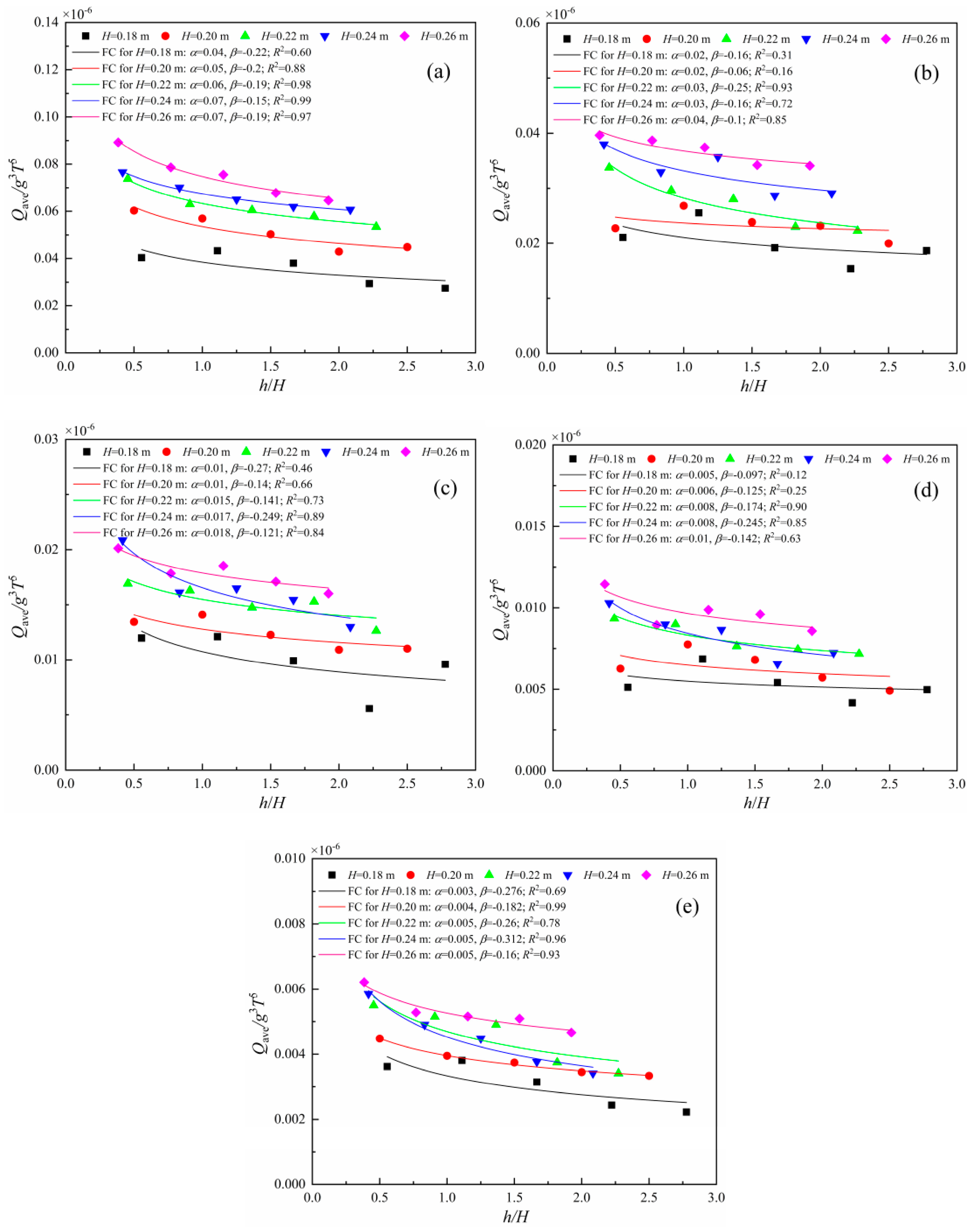
3.2. Aeration Depth Effect
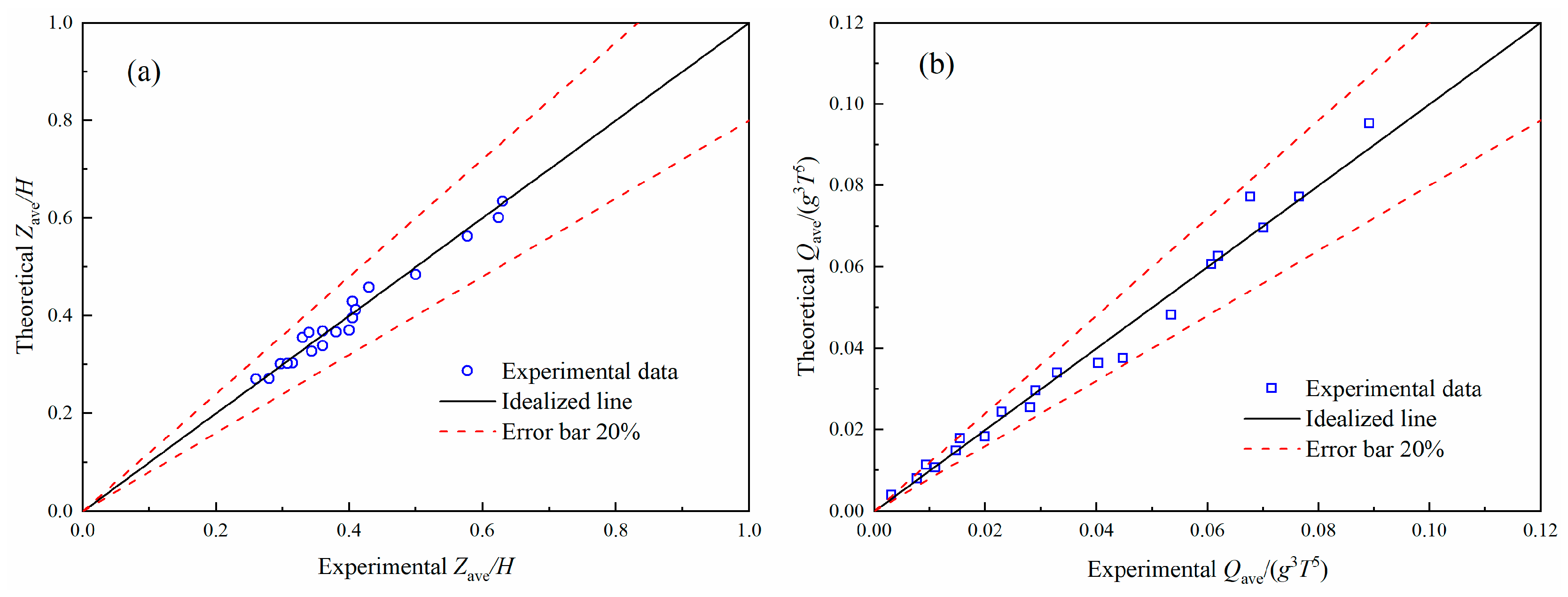
Figure 7 shows the Zave relationship with h for different H and T scenarios. It was observed that Zave decreased with increasing h in general. In detail, Zave decreased obviously from h = 0.1 m to 0.2 m and slightly from h = 0.4 m to 0.5 m. A possible explanation is that with increasing h, the water pressure at the outlet tube exit increased, it restricts the downward motion of heaving components with stronger effect and Zave decreased as a result. Consequently, it was expected that a higher h plays a negative role in Zave, especially for small T scenarios. Note that the maximum submerged depth hmax deserves a comment avoiding the unworkable result, and the wave parameters and the device geometry play complex roles in it. The friction between piston and air cylinder’s inner wall, the vertical wave force on the heaving components and the dynamics pressure of water were ignored to simplify the investigation and hmax can be expressed as m/ρwA (ρw = water density) when wave surface elevation is equal to still water level at the outlet tube exit location. In our experiments, hmax is estimated as 1.63 m larger than d = 1.0 m, ensuring the vertical motion of heaving components as well as the intermittent suck and release of air. In addition, Zave increases with increasing T approximately for given H and h scenarios, consistent well with the results as shown in Figure 3.
Figure 8 shows the Qave relationship with h for various H and T scenarios. It was found that Qave shows a decreasing tendency with increasing h roughly. However, some scattered data deviated to some extent especially for H = 0.18 m, 0.20 m and T = 1.8 s, 2.1 s and 2.4 s scenarios. The accurate explanation is still unknown to our knowledge and a possible reason is due mainly to the approach between the natural vibration period of heaving components and the incident wave periods of 1.8 s, 2.1 s and 2.4 s.
In order to examine the intrinsic characteristic between h and Zave, Figure 9 shows the relationship between the relative value of average heaving displacement Zave/H and the relative aeration depth h/H as well as their FCs. Note that the FCs also obey the power functions Zave/H = α(h/H)β with high correlation coefficients larger than 0.82. It was observed that Zave/H decreases with the increase of h/H, consistent well with the tendency as shown in Figure 7. Zave/H decays obviously for small h/H scenarios and it decreases slightly for high h/H scenarios in comparison. It is interesting to note that with increasing T, the Zave/H decay ratios gradually increased for small h/H scenarios; however, Zave/H reduced little for high h/H scenarios. For instance, with the increase of h/H from 0.38 to 2.78, the Zave/H value decreased from 0.4 to 0.2 for T = 1.5 s scenarios, it reduced from 0.59 to 0.21 for T = 1.8 s scenarios, it decreased from 0.66 to 0.26 for T = 2.1 s scenarios, it reduced from 0.7 to 0.29 for T = 2.4 s scenarios and it decreased from 0.71 to 0.3 for T = 2.7 s scenarios. Zave/H difference is very small between T = 2.4 s and 2.7 s as a result, which confirms that Zave/H is not sensitive to the incident wave period T variation for high T scenarios such as T = 2.4 s and T = 2.7 s.
Figure 10 shows the Qave/g3T5 relationship with respect to h/H. It was found that Qave/g3T5 decreased roughly with increasing h/H that follows a relatively weak power distribution Qave/g3T5 = α(h/H)β in comparison to Figure 5, Figure 6 and Figure 9, where α and β changed in terms to H variation. Note that a few data points deviated slightly especially for H = 0.18 m and a possible reason is that a smaller H greatly results in a smaller Qave and the accompanying decreases of its measurement accuracy. Note that Figure 4 showed that Qave increased with increasing H and Figure 8 showed that Qave decreased with increasing h, indicating that h/H plays a negative role in Qave/g3T5 and a small h/H contributed a great deal to the good hydrodynamic performance and high aeration efficiency of the device.

4. Discussion

Due to the significant contributions of the aforementioned parameters to the relative value of average heaving displacement Zave/H and the relative value of air flow rate Qave/g3T5, it is necessary to develop simple predictable equations to further the investigation. The incident wave height H, the incident wave length L (T equivalently) and the gravitational acceleration g are added to explore the wave effect. The aeration depth h was used to illustrate the effect of outlet tube exit location. The randomly selected 105 groups of laboratory data, the dimensional analysis and the least squares method are used to determine the following formulas,
Z ave H = 0.12 ( h H ) 0.39 ( H L ) 0.38
Q ave g 3 T 5 = 4.5 10 5 ( h H ) 0.15 ( H L ) 2.47
The correlation coefficients of Equations (1) and (2) are 0.80 and 0.95, respectively. The left 20 scenarios of experimental data were used to validate with respect to Equations (1) and (2) as shown in Figure 11. It was found that they agree satisfactorily with the corresponding experimental data; all the relative deviations between them are smaller than 20% and most of them are smaller than 10%. However, they were only derived from the laboratory data with 0.38 < h/H < 2.78 and 0.0022 < H/L < 0.0892 ranges, it is formidable to accurately predict with respect to the complex waves and the further investigation should involve the irregular wave effect to satisfy the device application of real sea as well as the DOC variation due to device. In addition, the device stability was controlled by using a support frame with the gravity base in the experiments. Concerning the real deep seawater, a mooring system could be used as an alternative to moor the device rather than the gravity base and its hydrodynamic characteristic should be considered in future research. It should be stated that fouling and biological species and so forth negatively affect the device performance in real sea and it is equally important to deal with the problems to ensure the safe and efficient operation of device.

5. Conclusions

In this paper, an innovative aeration device using a wave-driven heaving buoy was designed to produce the air bubbles for dealing with the hypoxia or anoxia problem of deep water and a series of physical experiments was conducted to investigate its hydrodynamic characteristics and aeration behavior. The wave parameters, the vertical motion of heaving components and the air flow rate were measured, and their relationship were explored respectively. The results illustrated that with increasing incident wave height, the average heaving displacement and the average air flow rate increase respectively. With the increase of incident wave steepness, the relative value of average heaving displacement increases obviously for high wave period scenarios, it increases slightly for small wave period scenarios in comparison and the relative value of air flow rate increases evidently. With the increase of aeration depth, the average heaving displacement and the average air flow rate decrease respectively. With the increase of relative aeration depth, the relative value of average heaving displacement and the relative value of air flow rate decrease respectively. In addition, the prediction formulas were deduced for the average heaving displacement and the average air flow rate by using the dimensional analysis and the least squares methods, and they were validated well with the related experimental data.
The limitations of this study should be pointed out clearly. First, some forces should be measured directly in the experiments, such as the wave excited force on the heaving components, the friction forces between the piston and the inner wall of air cylinder as well as between the pins and the slide bars. Simultaneously, their inducing effects on heaving motion should be taken into account in future analytical work. In addition, Equations (1) and (2) were deduced without the consideration of physical property and geometry effect of the device, such as the variation of its density and natural vibration period, and its physical property and geometry effect should be further investigated for the purpose of engineering application.

Author Contributions

Z.Y. and Y.W. initiated this research and wrote the manuscript, Y.L., C.G. and H.Z. provided recommendations on experimental issues. Z.Y. reviewed and improved this manuscript.

Funding

The study is financed by National Natural Science Foundation of China (Grant Nos. 51579229, 51879251), Key Research and Development Plan of Shandong Province, China (Grant No. 2017GHY15103) and State Key Laboratory of Ocean Engineering, China (Grant No. 1602).

Acknowledgments

All authors would like to thank the Ocean University of China for its support.

Conflicts of Interest

The authors declare no conflict of interest.

References

  1. Diaz, R.J.; Rosenberg, R. Spreading Dead Zones and Consequences for Marine Ecosystems. Science 2008, 321, 926–929. [Google Scholar] [CrossRef] [PubMed]
  2. Ram, A.; Jaiswar, J.R.M.; Rokade, M.A.; Bharti, S.; Vishwasrao, C.; Majithiya, D. Nutrients, hypoxia and mass fishkill events in Tapi Estuary, India. Estuar. Coast. Shelf Sci. 2014, 148, 48–58. [Google Scholar] [CrossRef]
  3. Ni, X.; Huang, D.; Zeng, D.; Zhang, T.; Li, H.; Chen, J. The impact of wind mixing on the variation of bottom dissolved oxygen off the changjiang estuary during summer. J. Mar. Syst. 2014, 154, 122–130. [Google Scholar] [CrossRef]
  4. Boettcher, E.J.; Fineberg, J.; Lathrop, D.P. Turbulence and wave breaking effects on air-water gas exchange. Phys. Rev. Lett. 2000, 85, 2030–2033. [Google Scholar] [CrossRef] [PubMed]
  5. Daniil, E.I.; Gulliver, J.S. Influence of waves on air-water gas transfer. J. Environ. Eng. 2015, 117, 522–540. [Google Scholar] [CrossRef]
  6. Taylor, P.K.; Yelland, M.J. The dependence of sea surface roughness on the height and steepness of the waves. J. Phys. Oceanogra. 2001, 31, 572–590. [Google Scholar] [CrossRef]
  7. Yin, Z.G.; David, Z.Z.; Liang, B.C.; Wang, L. Theoretical analysis and experimental study of oxygen transfer under regular and non-breaking waves. J. Hydrodyn. 2013, 25, 718–724. [Google Scholar] [CrossRef]
  8. Mahrt, L.; Vickers, D.; Howell, J.; Højstrup, J.; Wilczak, J.M.; Edson, J.; Hare, J. Sea surface drag coefficients in the Risø Air Sea Experiment. J. Geophys. Res. Oceans 1996, 101, 14327–14335. [Google Scholar] [CrossRef]
  9. Fairall, C.W.; Bariteau, L.; Grachev, A.A.; Hill, R.J.; Wolfe, D.E.; Brewer, W.A.; Tucker, S.C.; Hare, J.E.; Angevine, W.M. Turbulent bulk transfer coefficients and ozone deposition velocity in the International Consortium for Atmospheric Research into Transport and Transformation. J. Geophys. Res. Oceans 2006, 111, D23S20. [Google Scholar] [CrossRef]
  10. Vickers, D.; Mahrt, L. Sea-surface roughness lengths in the midlatitude coastal zone. Quarterly J. R. Meteorol. Soc. 2010, 136, 1089–1093. [Google Scholar] [CrossRef] [Green Version]
  11. Grachev, A.A.; Bariteau, L.; Fairall, C.W.; Hare, J.E.; Helmig, D.; Hueber, J.; Lang, E.K. Turbulent fluxes and transfer of trace gases from ship-based measurements during TexAQS 2006. J. Geophys. Res. Oceans 2011, 116, D13110. [Google Scholar] [CrossRef]
  12. Grachev, A.A; Leo, L.S.; Fernando, H.J.S.; Fairall, C.W.; Creegan, E.; Blomquist, B.W.; Christman, A.J.; Hocut, C.M. Air-sea/land interaction in the coastal zone. Bound. Layer Meteorol. 2018, 167, 181–210. [Google Scholar] [CrossRef]
  13. Jiménez, P.A.; Dudhia, J. On the need to modify the sea surface roughness formulation over shallow waters. J. Appl. Meteorol. Clim. 2018, 57, 1101–1110. [Google Scholar] [CrossRef]
  14. Stommel, H.; Arons, A.B.; Blanchard, D. An oceanographical curiosity: The perpetual salt fountain. Deep Sea Res. 1956, 3, 152–153. [Google Scholar] [CrossRef]
  15. Liu, C.C.K.; Jin, Q. Artificial upwelling in regular and random waves. Ocean. Eng. 1995, 22, 337–350. [Google Scholar] [CrossRef]
  16. Fan, W.; Pan, Y.; Liu, C.C.K.; Wiltshire, J.C.; Chen, C.T.A.; Chen, Y. Hydrodynamic design of deep ocean water discharge for the creation of a nutrient-rich plume in the south china sea. Ocean. Eng. 2015, 108, 356–368. [Google Scholar] [CrossRef]
  17. Fan, W.; Chen, J.; Pan, Y.; Huang, H.; Chen, C.T.A.; Chen, Y. Experimental study on the performance of an air-lift pump for artificial upwelling. Ocean. Eng. 2013, 59, 47–57. [Google Scholar] [CrossRef]
  18. Antonini, A.; Lamberti, A.; Archetti, R.; Miquel, A.M. CFD investigations of oxyflux device, an innovative wave pump technology for artificial downwelling of surface water. Appl. Ocean. Res. 2016, 61, 16–31. [Google Scholar] [CrossRef]
  19. Antonini, A.; Lamberti, A.; Archetti, R. Oxyflux, an innovative wave-driven device for the oxygenation of deep layers in coastal areas: A physical investigation. Coast. Eng. 2015, 104, 54–68. [Google Scholar] [CrossRef]
  20. Endo, A.; Srithongouthai, S.; Nashiki, H.; Teshiba, I.; Iwasaki, T.; Hama, D.; Tsutsumi, H. Do-increasing effects of a microscopic bubble generating system in a fish farm. Mar. Pollut. Bull. 2008, 57, 78–85. [Google Scholar] [CrossRef] [PubMed]
  21. Cong, H.B.; Huang, T.L.; Chai, B.B.; Zhao, J.W. A new mixing-oxygenating technology for water quality improvement of urban water source and its implication in a reservoir. Renew. Energy 2009, 34, 2054–2060. [Google Scholar] [CrossRef]
  22. Zhou, X.; Wu, Y.; Shi, H.; Song, Y. Evaluation of oxygen transfer parameters of fine-bubble aeration system in plug flow aeration tank of wastewater treatment plant. J. Environ. Sci. 2013, 25, 295–301. [Google Scholar] [CrossRef]
  23. Yin, Z.G.; David, Z.Z.; Cheng, D.S; Liang, B.C. Oxygen transfer by air injection in horizontal pipe flow. J. Environ. Eng. 2013, 139, 908–912. [Google Scholar] [CrossRef]
  24. Zelt, J.A.; Skjelbreia, J. Estimating Incident and Reflected Wave Fields Using an Arbitrary Number of Wave Gauges. In Proceedings of the 23rd International Conference on Coastal Engineering, Venice, Italy, 4–9 October 1992. [Google Scholar] [CrossRef]
  25. Xie, J.; Gao, H.T.; Ye, X.Y.; Gu, F.Q.; Li, D.S. Application of laser sensors for on-line calibration of displacement transducers. In Proceedings of the 6th International Symposium on Precision Engineering Measurements and Instrumentation, Hangzhou, China, 31 December 2010. [Google Scholar] [CrossRef]
  26. Yang, Z.; Ji, Y.; Bi, N.; Lei, K.; Wang, H. Sediment transport off the Huanghe (Yellow River) delta and in the adjacent Bohai Sea in winter and seasonal comparison. Estuar. Coast. Shelf Sci. 2011, 93, 173–181. [Google Scholar] [CrossRef]
  27. Airy, G.B. Tides and Waves: Extracted from the Encyclopaedia Metropolitana; William Clowes Ltd.: London, UK, 1845; pp. 241–396. [Google Scholar]
  28. Frostick, L.E.; Mclelland, S.J.; Mercer, T.G. Users Guide to Physical Modelling and Experimentation: Experience of the HYDRALAB Network; CRC Press: London, UK, 2011. [Google Scholar]
Figure 1. Device sketch (a) Whole components; (b) Heaving components; (c) Immovable components.
Energies 11 03262 g001
Figure 2. Experimental sketch.
Energies 11 03262 g002
Figure 3. Zave relationship with H. (a) h = 0.1 m; (b) h = 0.2 m; (c) h = 0.3 m; (d) h = 0.4 m; (e) h = 0.5 m.
Energies 11 03262 g003
Figure 4. Qave relationship with H. (a) h = 0.1 m; (b) h = 0.2 m; (c) h = 0.3 m; (d) h = 0.4 m; (e) h = 0.5 m.
Energies 11 03262 g004
Figure 5. Zave/H relationship with H/L. (a) h = 0.1 m; (b) h = 0.2 m; (c) h = 0.3 m; (d) h = 0.4 m; (e) h = 0.5 m.
Energies 11 03262 g005
Figure 6. Qave/g3T5 relationship with H/L. (a) h = 0.1 m; (b) h = 0.2 m; (c) h = 0.3 m; (d) h = 0.4 m; (e) h = 0.5 m.
Energies 11 03262 g006
Figure 7. Zave relationship with h. (a) H = 0.18 m; (b) H = 0.20 m; (c) H = 0.22 m; (d) H = 0.24 m; (e) H = 0.26 m.
Energies 11 03262 g007
Figure 8. Qave relationship with h. (a) H = 0.18 m; (b) H = 0.20 m; (c) H = 0.22 m; (d) H = 0.24 m; (e) H = 0.26 m.
Energies 11 03262 g008
Figure 9. Zave/H relationship with h/H. (a) T = 1.5 s; (b) T = 1.8 s; (c) T = 2.1 s; (d) T = 2.4 s; (e) T = 2.7 s.
Energies 11 03262 g009
Figure 10. Qave/g3T5 relationship with h/H. (a) T = 1.5 s; (b) T = 1.8 s; (c) T = 2.1 s; (d) T = 2.4 s; (e) T = 2.7 s.
Energies 11 03262 g010
Figure 11. Validation of (a) Zave/H and (b) Qave/g3T5 equations with experimental data.
Energies 11 03262 g011

