1. Introduction
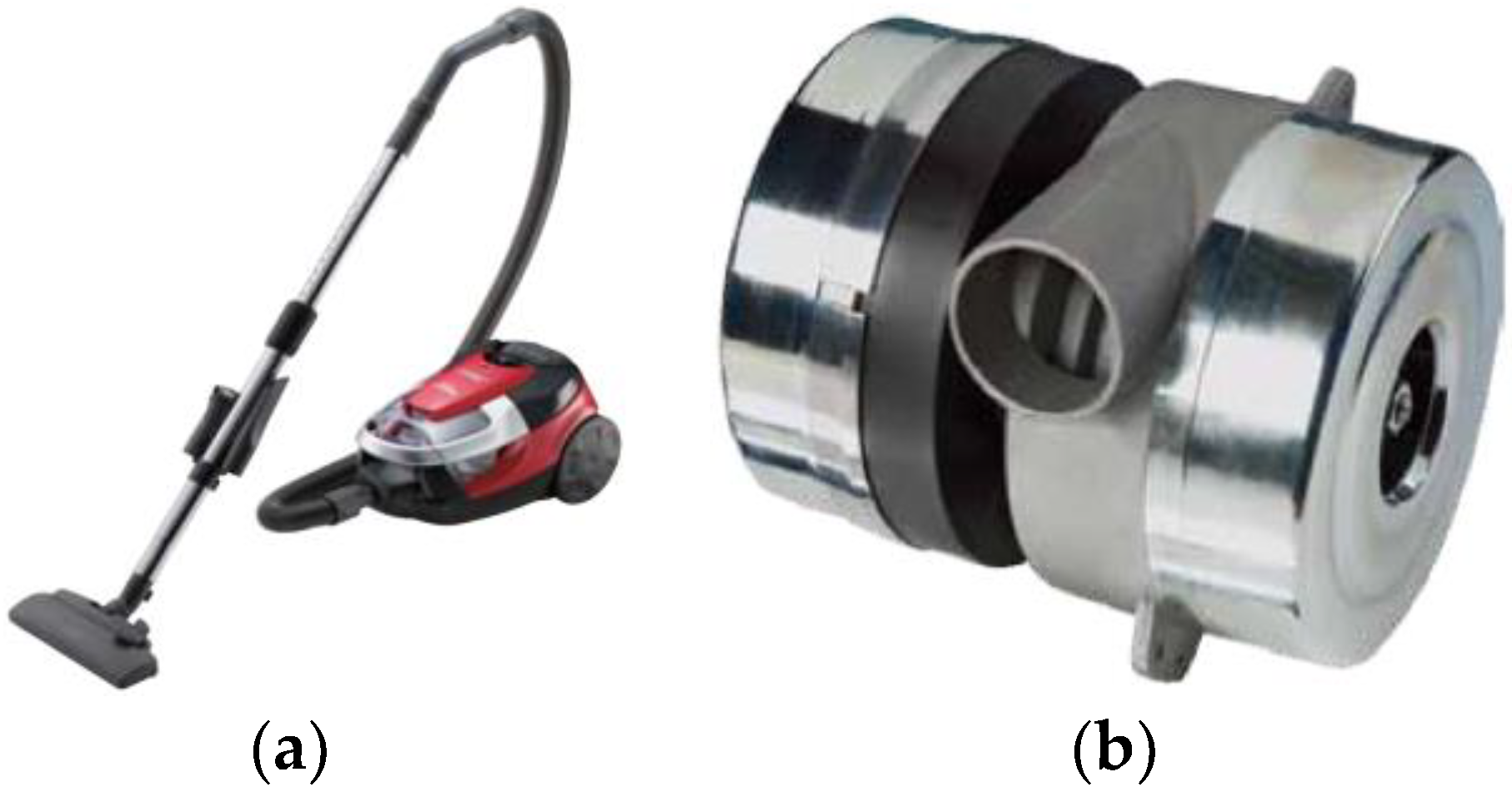
An important characteristic of vacuum cleaners (
Figure 1a) and air blowers (
Figure 1b) is the suction power, which directly depends on the power of the applied electric motor [
1]. One prospective of such devices is the increase in suction power without increasing the size and mass of devices. In addition, to improve reliability and durability, it is necessary to eliminate the collector-and-brush motor assembly unit. However, these requirements cannot be satisfied with the use of an AC commutator (brushed, universal) motor (
Figure 2a), traditionally used in vacuum cleaners and air blowers [
2,
3]. Therefore, for the application under consideration, the use of brushless electric motors is promising [
2,
3,
4,
5,
6].
A high-speed three-phase brushless synchronous motor for vacuum cleaners and air blowers [
2] is shown in
Figure 2b and a two-phase switched reluctance motor [
3] is demonstrated in
Figure 2c.
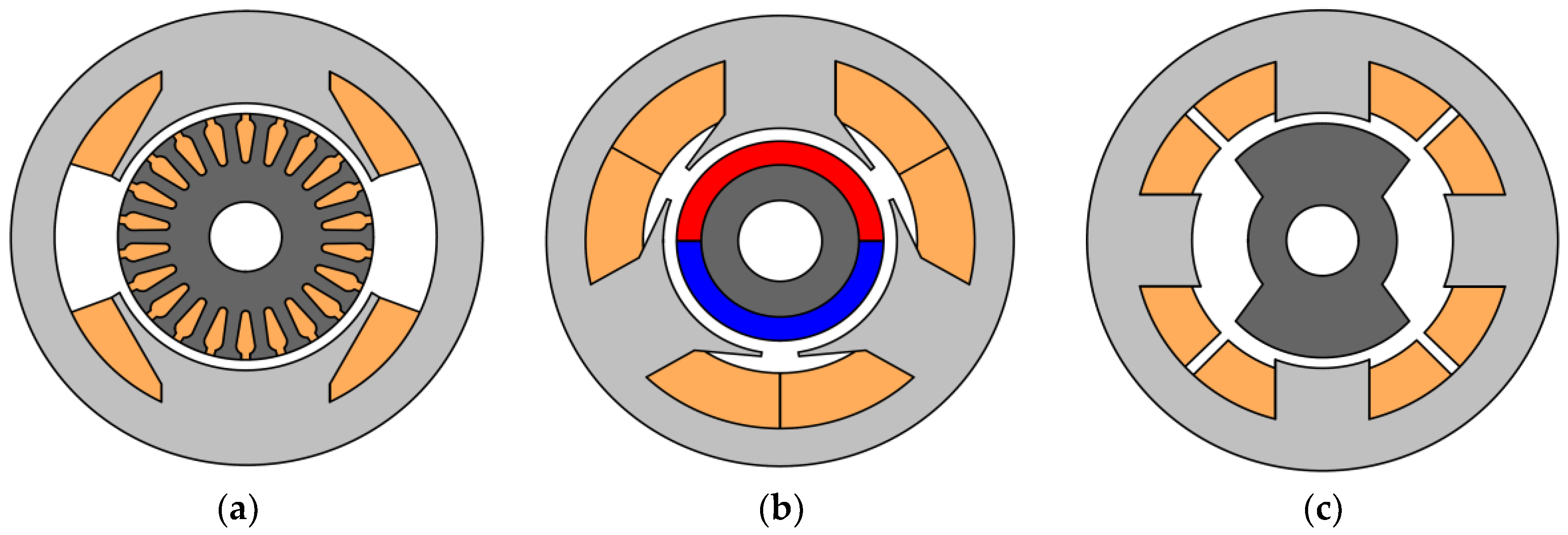
In high-speed vacuum cleaners and air blowers the use a type of motor with magnets on the stator is expected, which is known as a flux reversal motor [
7,
8]. Two possible designs of the high-speed flux reversal motor are shown in
Figure 3.
A flux reversal machine (FRM) has many advantages in comparison with other types of high-speed machines [
7].
When compared to AC commutator motors [
11], the main advantages of an FRM are the following:
The FRM is more reliable and its lifetime is longer, as it has no collector assembly and no brushes;
The heat removal from the rotor is not required because the rotor does not contain any heating elements such as coils or a collector. This also increases the reliability of the rotor bearings;
The toothed rotor production is very simple and not necessarily required. Its only active part is a magnetic core made of laminated steel;
The FRM mass is much less than that of the AC commutator motor with brushes;
The efficiency of the FRM is higher than that of the AC commutator motor with brushes.
The main advantages of the FRM over three-phase and single-phase synchronous motors having permanent magnets (PM) on the rotor [
2,
12,
13] are the following:
The toothed rotor of the FRM is simpler and more reliable, without permanent magnets;
High-speed synchronous motors with magnets on the rotor often have an additional retaining ring on the rotor to fix the magnets;
The FRM rotor is simpler, more reliable, and does not require balancing.
In addition to this, the FRM single-phase inverter is simpler and cheaper than a three-phase synchronous motor with PMs on the rotor.
The FRM has similar advantages at high-speed applications to the Switched Reluctance Motor (SRM), since both have a simple and reliable rotor.
When compared to the two-phase SRM [
14], the additional advantages of the FRM are the following:
Only half a period is used to generate torque in the SRM, while the FRM can do it for almost an entire period, which increases the efficiency as well as the specific torque and power;
The SRM has open stator slots [
14] and only about half the stator surface is used, which decreases the efficiency as well as the specific torque and power;
Almost half of the electrical energy received by the SRM returns to its inverter and does not transform to mechanical energy, which increases the winding current as well as increasing the inverter cost and size;
The single-phase inverter (control circuit of the motor) for the FRM is simpler and cheaper compared to the inverter for the two-phase SRM.
Given the advantages noted above in high-speed applications where a large starting torque is not required (vacuum cleaners, hand dryers, blowers, etc.), the use of a single-phase FRM is a good alternative to the SRM and synchronous motors with PMs on the rotor.
Recently, a large number of three-phase configurations of the FRM were described in the literature [
15,
16,
17]. However, the three-phase FRMs require both a more expensive power converter and a complicated control system. Therefore, in the considered application, the use of a single-phase FRM that has a simple converter design [
7] is more preferable.
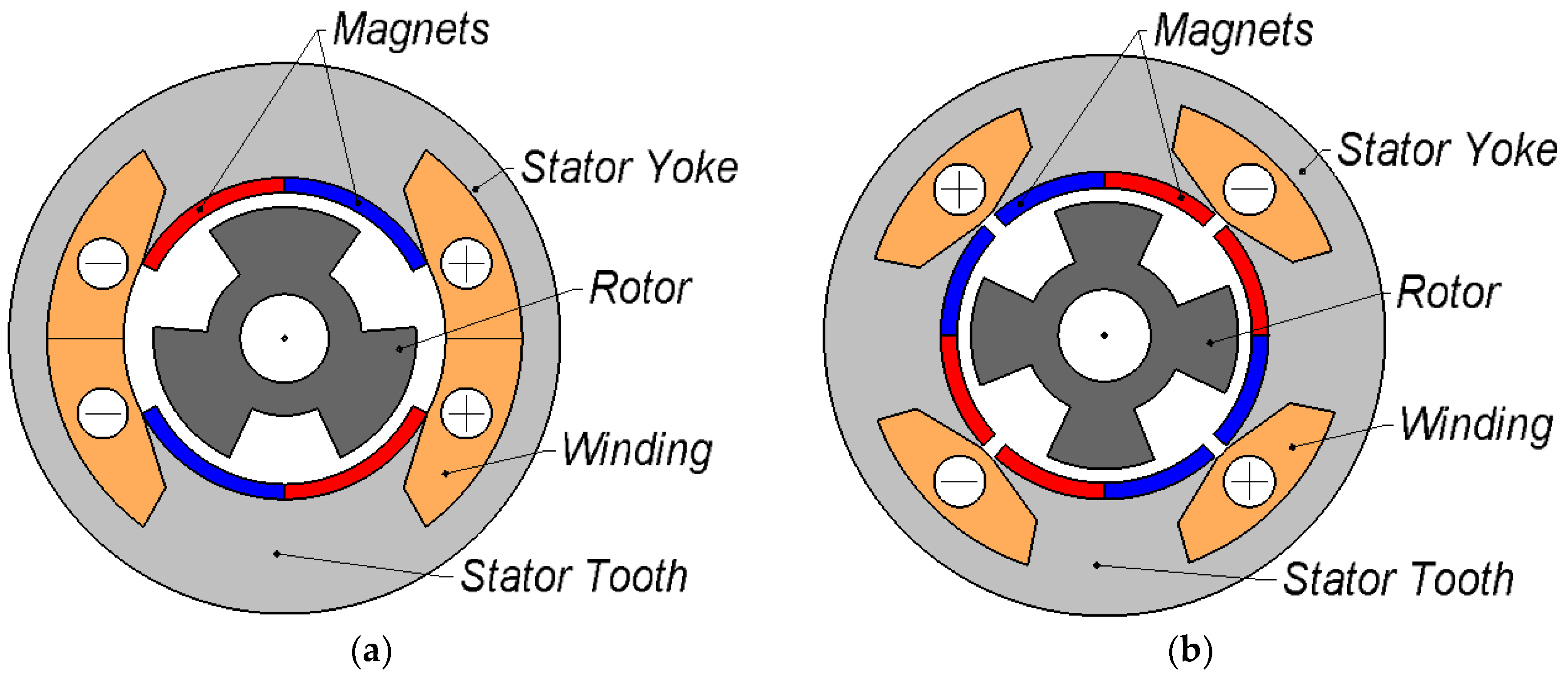
The design of a single-phase FRM is not so often discussed in the literature. At present, only several various configurations of a single-phase FRM are known. Ref. [
18] describes the first known configuration of the single-phase FRM. This machine has two stator teeth with two magnetic poles on each, and three rotor teeth (
Figure 3a). A similar high-speed FRM for vacuum cleaners is described in Reference [
19].
Single-phase FRMs, in which the inner stator surface is entirely used, are described in Reference [
7,
20]. This FRM operates at a very high speed (≈28,000 rpm). This machine was considered for driving an angular grinder (electric power hand tool).
Figure 3b shows the design of that FRM. Its stator consists of a stator core with four teeth and a four-pole single-phase winding. On the internal surface of each stator tooth there are two fixed PMs. The direction of the magnetization of the nearest PMs fixed on the adjacent teeth is the same. In addition to this, the new FRM’s design has a rotor with four teeth.
When compared to the well-known modifications of FRMs [
18,
19], the advantages of the considered design (
Figure 3b) are the following: (1) increasing mechanical power density and efficiency of the motor, due to better utilization of the stator internal surface; (2) no inherent uncompensated radial forces; and (3) an increase in the lifetime of the bearings as a result of the symmetry of the motor with an even number of rotor teeth.
Various approaches to the modeling of the FRM were presented in References [
7,
18,
19]. The optimization of the geometry of the FRM with three rotor teeth (
Figure 3a) was discussed in Reference [
18]. However, the criterion of optimization was not presented. The calculation of the performances of the FRM was carried out using parameters such as the “fringing coefficient”, obtained from an FEM (finite element method) model. Furthermore, it was not mentioned in the paper how the steel saturation was accounted for in the model.
Another approach was presented in Reference [
19]. The Simulink implemented model of an FRM is based on data on inductance, and back EMF (electromotive force) obtained from an FEM model. The model does not take into consideration losses in the magnetic cores and magnets, which may be essential at high frequencies.
When designing the FRM for a variable-speed application, it is necessary to take into account the lack of FRM inherent in all motors with magnets. Their magnetic field cannot be switched off or weakened at low loads. Therefore, with a suboptimal motor design for the rated mode, the losses at underload will be significant, and the efficiency will be low. This necessitates the minimization of FRM losses over a wide range of load modes.
In this paper, the optimal design technique of a high-speed FRM for a vacuum cleaner, choosing the optimization criterion, and the selection of the optimization algorithm are described. The characteristics of single-phase FRMs designed without the optimization and those of single-phase FRMs designed with the optimization are compared.
An FEM-based mathematical model was developed for this optimization. The case of feeding the FRM with the voltage of a rectangular waveform is considered. To reduce the number of boundary problems required, the motor symmetry is studied. The iterating procedure followed to converge the model with the mode at a given power is described.
2. Brief Description of the New FRM Mathematical Model
A new mathematical model was developed for an optimal FRM design. The rectangular voltage form is assumed in the model. The winding, magnets, and core losses are neglected in solving the boundary problems and are estimated in the post-processing.
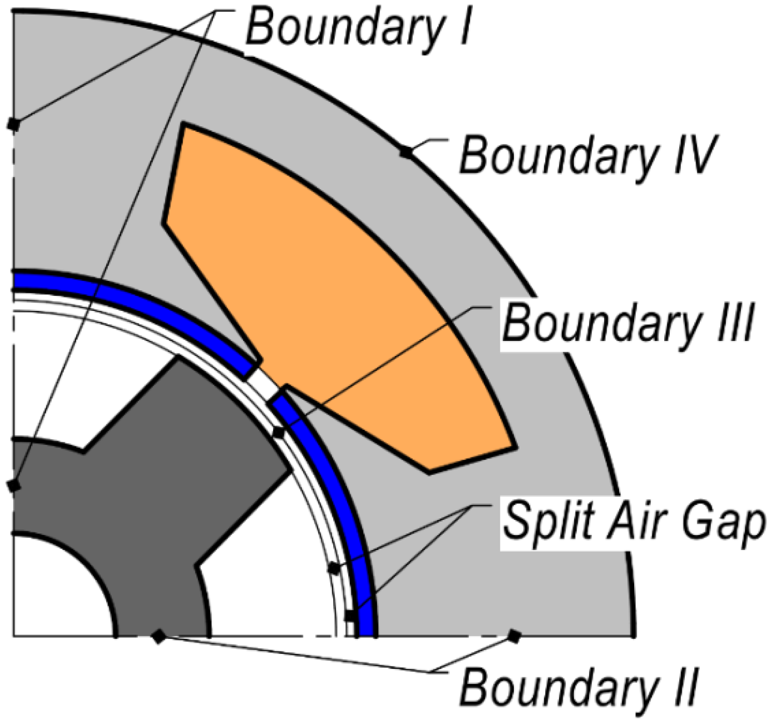
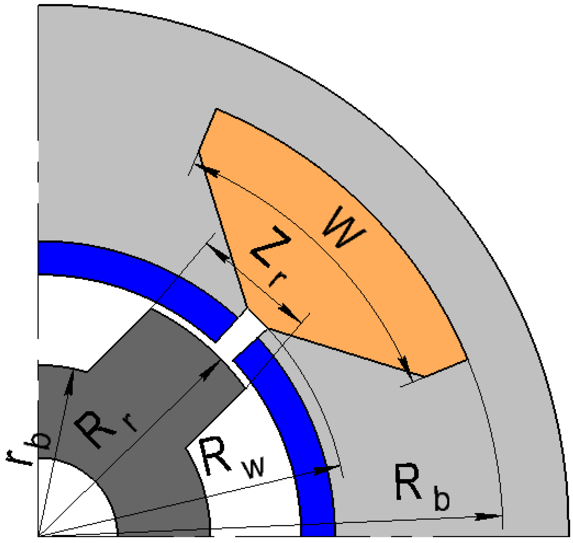
The flux waveform is trapezoidal and can be obtain by integrating the voltage waveform. The rotor speed is assumed to be a constant during the machine’s electrical cycle (rotating the rotor by 90 mechanical degrees). The integration constant is chosen so that the average current is equal to zero. Thus, only a few combinations of the flux and the rotor position are realized in the machine cycle, and only the boundary problems corresponding to these combinations should be solved. Therefore, considering all possible combinations is not required. A 2D magnetic vector potential approach was applied to solve these boundary problems. This approach involved dividing the calculated area into two subareas corresponding to the rotor and the stator by boundary III (
Figure 4), using a joining boundary condition depending on whether the rotor position allowed, using one and the same geometry for all the boundary problems, and considering the rotor and the stator in their own reference frames. Such an approach simplifies the calculation of the total time derivative of the magnetic flux density necessary for the calculation of the core and magnet losses.
The geometry of the FRM is symmetrical with respect to its rotation by 90 mechanical degrees and changing the current and magnetization directions. Therefore, it is sufficient to consider only a ¼ section of the geometry. The boundaries I and II are linked by an antiperiodic boundary condition where the vector magnetic potential changes its sign.
Usually, for the boundary problem to be solved, the current density should be given. However, when the flux
is given, the current density
J is assumed to be proportional to the unknown winding current
I:
where
is the current density at the winding current of 1A. The winding current
I should be considered an additional degree of freedom. The corresponding equation is:
where
A is the z-component of magnetic potential,
L is the stack length, and 4 is the multiplier, taking into account the reduction of the calculating area.
As a result of solving the set of boundary problems, the current waveform can be found. Then the torque and the winding losses can be estimated in postprocessing. In particular, the torque
T can be found as follows:
where
is the air gap thickness.
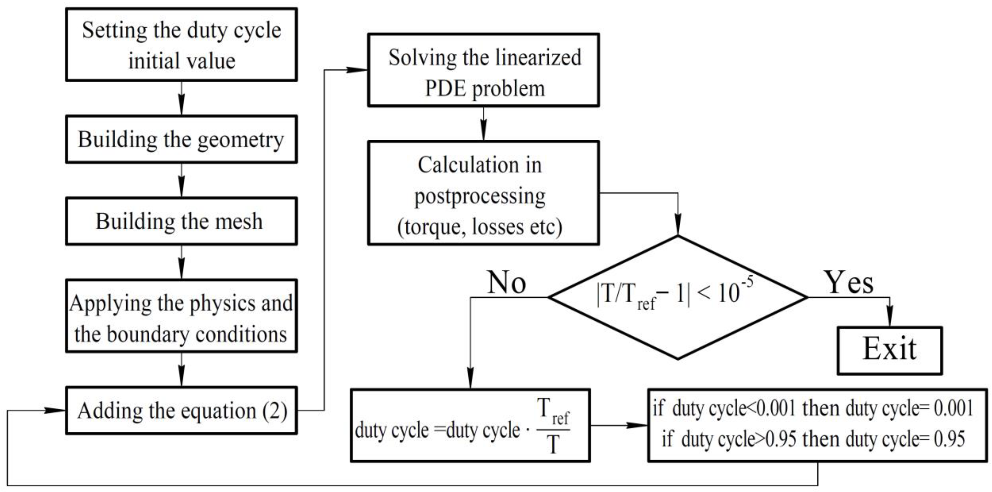
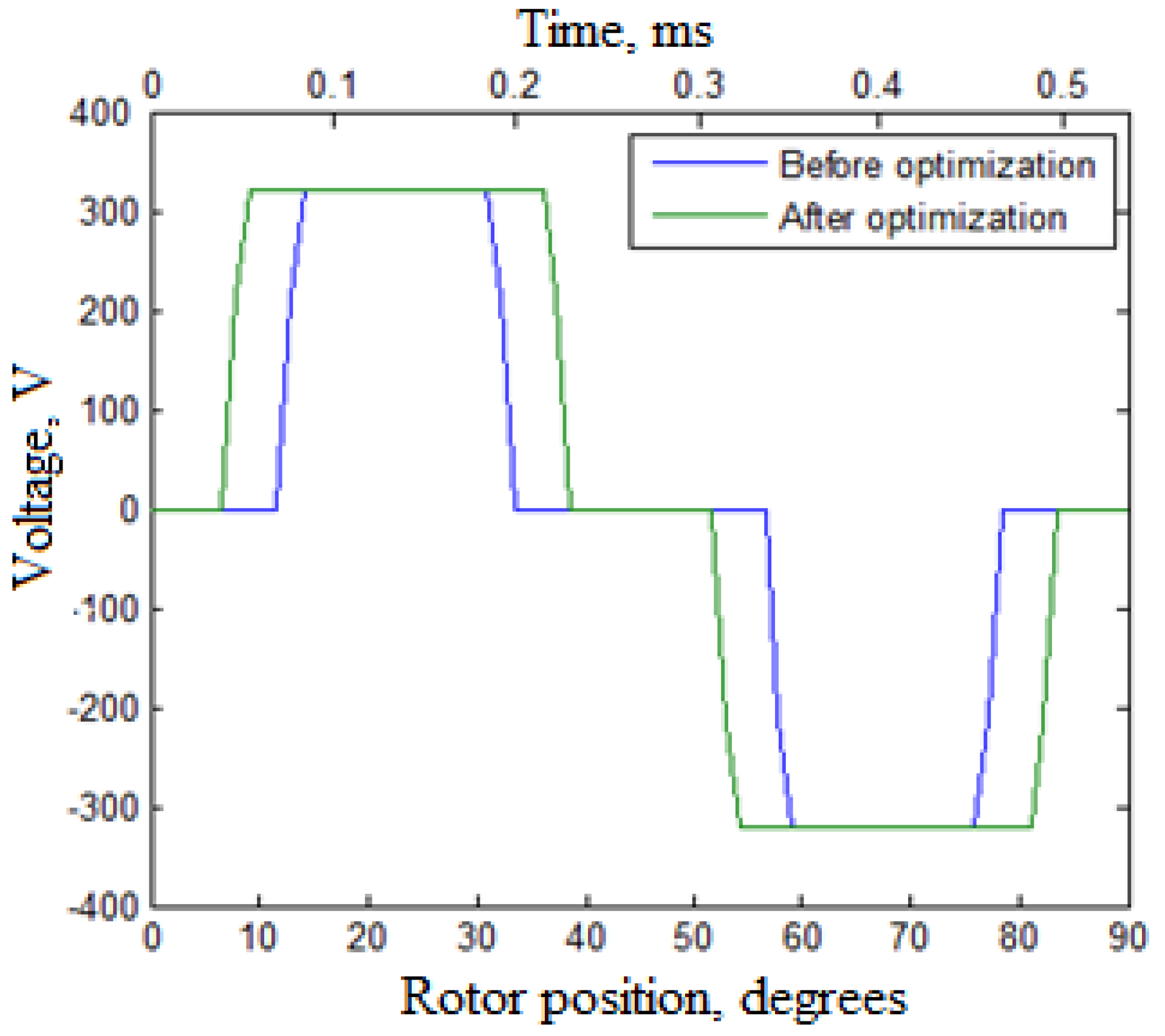
It is supposed that the middles of the impulses of the rectangular supply voltage correspond to the moments of time when the rotor teeth are exactly over the magnetic poles of the stator teeth. Therefore, the only way to affect the operating mode is to choose the duty-cycle that is the part of time when the applied voltage is not zero. The duty cycle through the applied voltage determines the flux waveform involved in Equation (2). To calculate the motor mode with the given torque
Tref and speed, an algorithm was developed and its flowchart is shown in
Figure 5. When the torque is equal to
Tref with the required accuracy, the calculations stop.
3. The FRM Optimization Criteria and Procedure
Since the vacuum cleaner works in a wide range of speeds and torques depending on the operating mode, the rated efficiency cannot serve as a correct indicator of the energy efficiency of the vacuum cleaner. As a quantitative measure of energy efficiency for a variable-load motor, the average efficiency can be used:
where
is the mechanical power in different modes;
denotes the value of active electrical power in various modes; and
is the proportion of the operating time of a certain mode.
The modes of the operation of the variable-speed motor are chosen by analogy with the recommendations from Reference [
21] for fan load (quadratic dependence of torque and speed) and are given in
Table 1.
Typically, fan units are operated with a substantial underload for a longer time. Therefore, in Reference [
21] it was proposed to use the arithmetic average efficiency in the modes
i = 1, 2, 3 as a measure of the energy efficiency of the pump motor, which corresponds to
ti ~ 1/
Pai.
The vacuum cleaner is designed for cleaning dust from different surfaces with a hard-to-predict aerodynamic resistance. Therefore, it was accepted that all modes are implemented at the same time. Therefore, Equation (4) transforms into Equation (5):
This value was chosen as the optimization criterion. When the optimization criterion has many local extrema, the heuristic Monte Carlo methods such as genetic algorithms and simulated annealing algorithms [
22] are usually applied.
The optimization criteria used in the optimal design of electric motors have fewer extrema. However, using gradient descent optimization algorithms such as the Newton algorithm or trust region methods [
23,
24] together with FEM-based models is almost impossible, because the calculations using FEM are accompanied by the unpredictable pseudorandom computational error [
25] and the derivatives calculations of the optimization criterion become complicated.
To overcome these difficulties, the type of gradient-free method known as the Nelder–Mead method [
25] is used in this work. This method is based upon the comparison of the criterion values for various cases, but not upon their numerical values. Therefore, it can be used for noisy or non-smooth functions. Moreover, it can be more effective than some other gradient-free methods, in particular, the Powell method [
26].
The proposed criterion (5) requires the calculations of three motor modes per one calculation step. However, as a result, higher efficiency at a wide range of operating modes and not only at the rated conditions can be achieved. It also provides a longer running time for a vacuum cleaner battery with the FRM assuming the same capacity as the battery.
The fixed parameters of the designed FRM for the vacuum cleaner are as follows: the rated speed is 28,000 rpm; the rated power is 1.5 kW; the outer diameter of the stator is 54 mm; the length of the stator lamination is 40 mm; the air gap is 0.4 mm. The FRM requires magnets with a residual flux density of 1.3 T. Each magnet is divided into eight electrically insulated pieces in the azimuthal direction to reduce the eddy current losses. The magnet thickness is assumed to be 1.7 mm because thinner magnets have a higher price per kg and thus would not reduce the motor cost. M330-50A steel grade was chosen.
Figure 6 shows the optimization parameters:
4. The Results of the Optimization
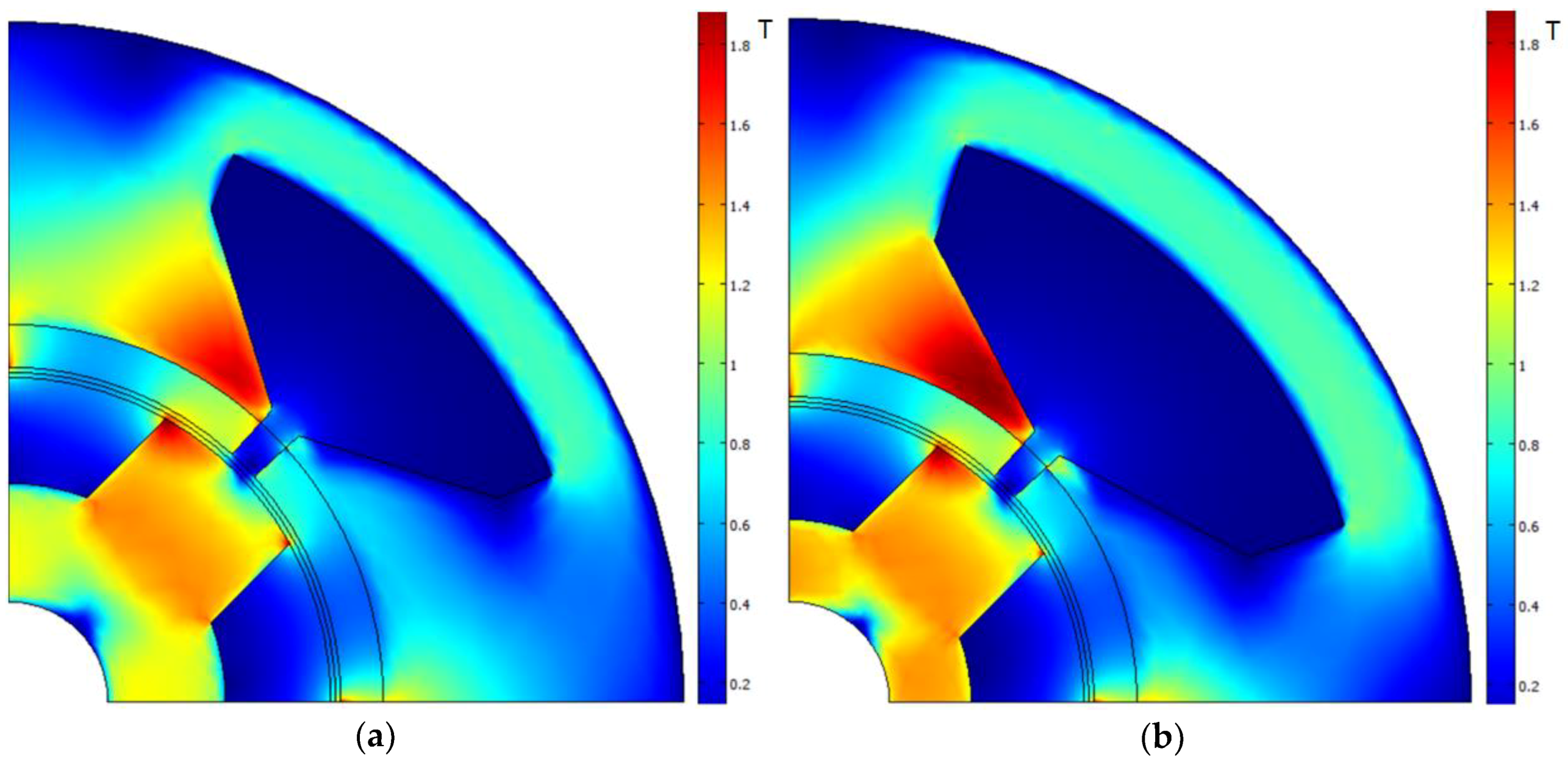
To obtain the maximum value of Equation (5), the human-made design (shown in
Figure 7a) was used as a starting point.
Figure 7b shows the optimized design. The optimization parameters before and after the optimization are shown in
Table 2.
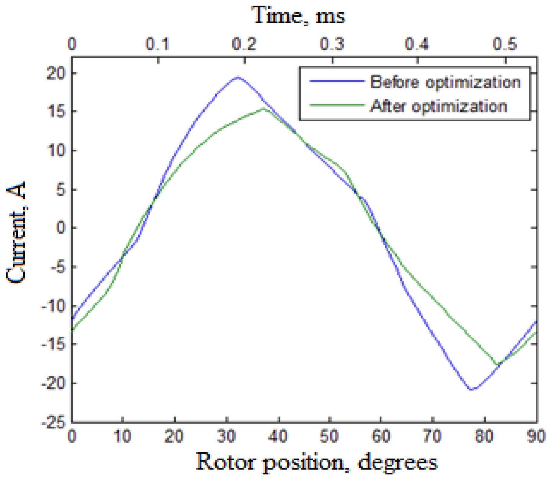
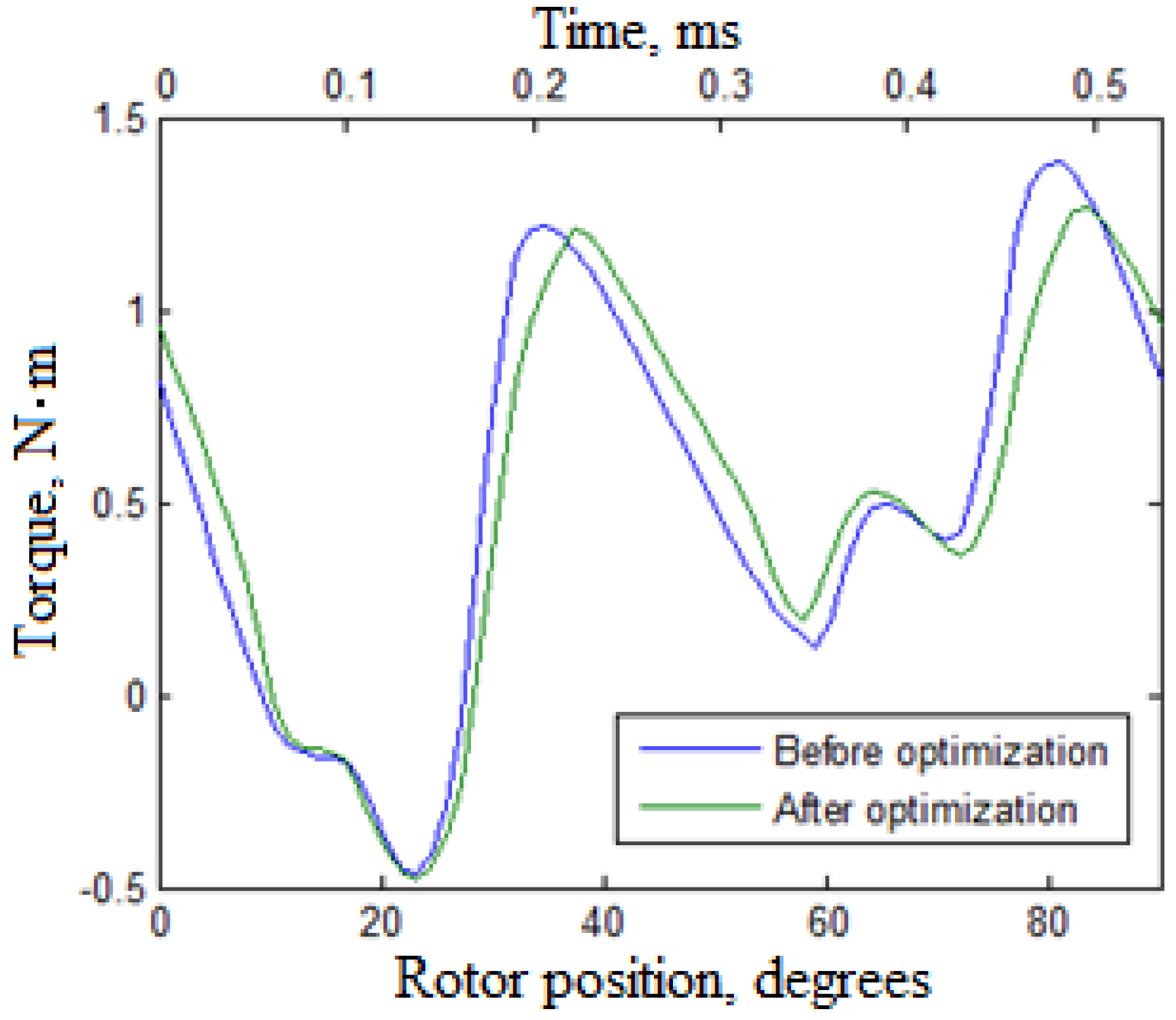
Figure 8,
Figure 9 and
Figure 10 show the transient values of the current, the voltage, and the torque depending on the rotor position for the rated mode (mode № 3, 28,000 rpm, 1.5 kW).
Like other single-phase motors, both considered FRMs before and after the optimization have a high torque ripple. However, the torque ripple of the optimized FRM is a little lower, although it was not included in the optimization criterion.
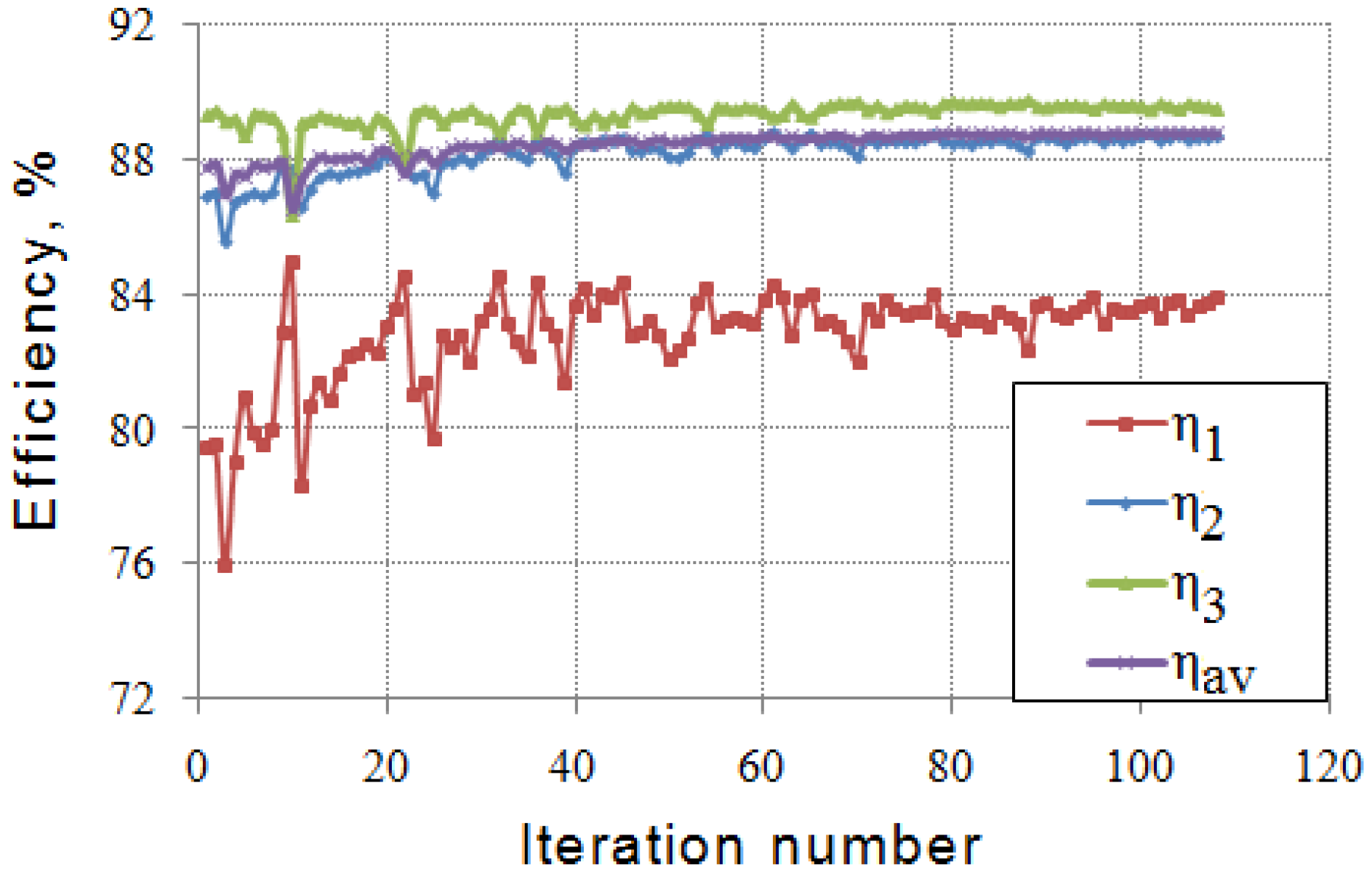
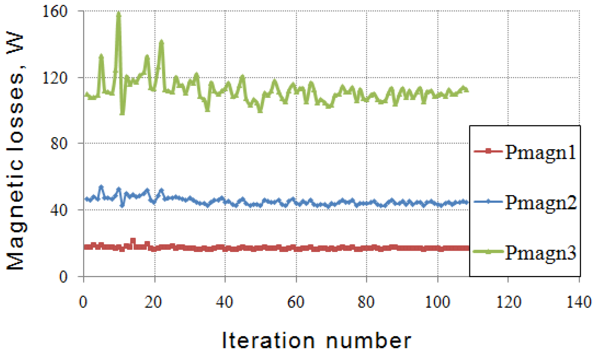
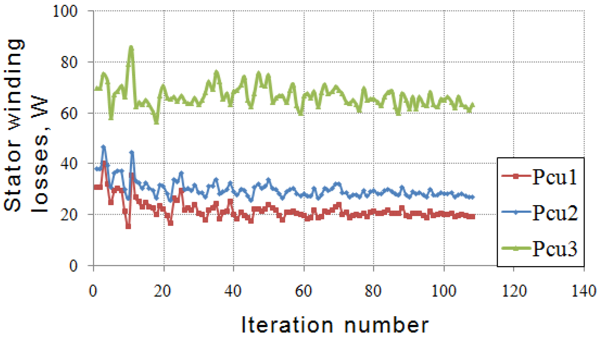
Figure 11,
Figure 12 and
Figure 13 illustrate the change in the efficiencies and losses for the three modes considered in
Table 1, as well as motor losses during the optimization procedure. The change in the average efficiency (Equation (5)) is also shown. From these data, it can be concluded that, most of all, the efficiency in the least loaded mode η
1 (more than 4%) was increased. The efficiency in two other modes (η
2 and η
3) was increased by 1.7% and 0.3%, respectively. The magnetic losses
Pmagn (the sum of losses in steel and magnets,
Figure 12) remain approximately constant (
Pmangn1 is the loss in the least loaded mode;
Pmangn3 is the loss in the most loaded mode). The increase in efficiency is mainly due to a decrease in loss in the stator winding
Pcu (
Figure 13,
Pcu1 is the loss in the least loaded mode;
Pcu3 is the loss in the most loaded mode). The whole optimization process requires about 110 iterations.
Table 3 specifies the FRM characteristics before and after the optimization. Although the magnets’ thickness was not varied, their mass was reduced during the optimization due to the reduction of the outer rotor radius.
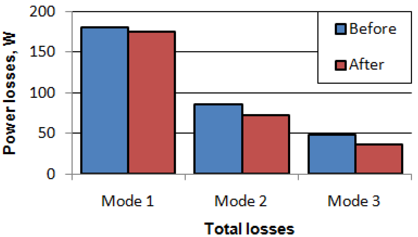
In
Figure 14, the total motor losses before and after the optimization are shown. In
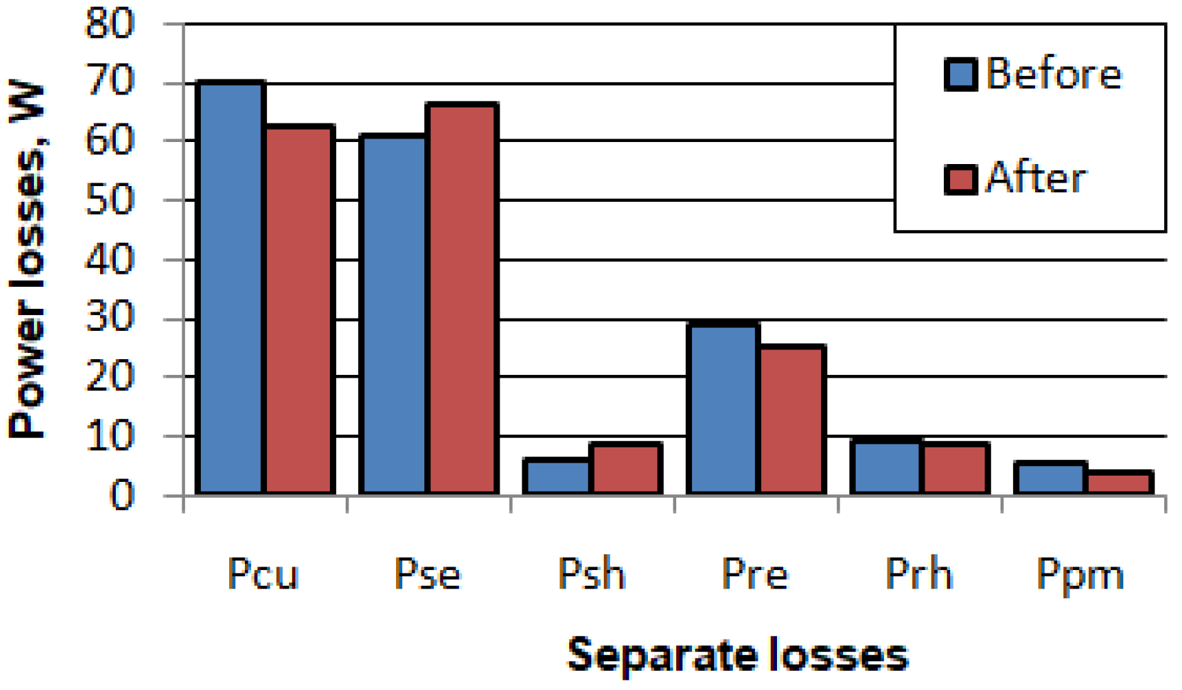
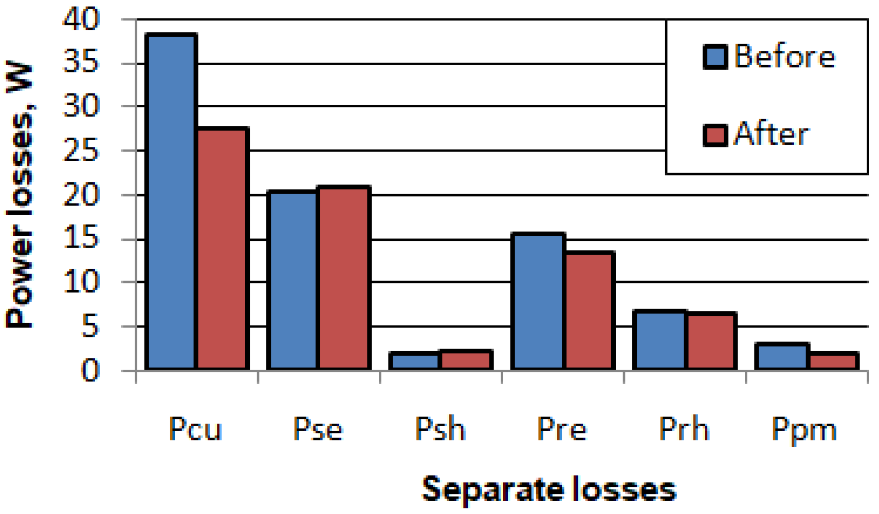
Figure 15,
Figure 16 and
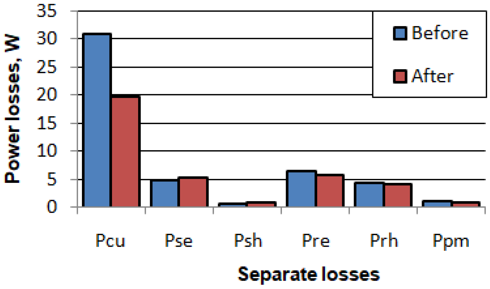
Figure 17, the electric losses in various parts of the motor are shown for the various load modes. In
Figure 15,
Figure 16 and
Figure 17, the following designations of certain types of motor losses are accepted:
Pcu is the loss in the stator winding;
Pse is the loss in the stator steel from eddy currents;
Psh is the loss in the stator steel due to hysteresis;
Pre is the loss in the rotor steel from eddy currents;
Prh is the loss in the rotor steel due to hysteresis;
Ppm is the loss in permanent magnets.
The reduction of the total losses due to optimization was most significant at underload. Thus, the total losses were decreased by 11.8 W (24%) at mode 1, by 12.7 W (15%) at mode 2, and by 5.1 W (3%) at mode 3. The main contribution to the reduction of the total losses is provided by the reduction of the winding losses, which is obtained by increasing the copper mass and stator slot area.
The core losses exhibited insignificant changes. However, they also should be taken into account when calculating the efficiency. Hence, the only way to decrease further core losses and to increase the efficiency is by using thinner steel sheets with lower specific losses, and, in particular, eddy current losses. The core losses are significant in the rated mode and they are very small at underload while the winding losses prevail in underload. Therefore, a further increase in the rated efficiency is possible with the use of thinner steel in the manufacture of magnetic cores. The losses in magnets are very small. So, the number of parts in which magnets are divided can be slightly increased without significantly decreasing the efficiency if it reduces the FRM production cost.
Although the windage losses constitute a significant part in the total losses, especially when a high-speed motor has a toothed rotor, they were not taken into account. However, during the optimization, the rotor slot became smaller. Therefore, the reduction of the windage losses is expected.
5. Conclusions
This paper describes the design of a high-speed single-phase flux reversal motor for vacuum cleaners. This machine has a simple and reliable rotor, which is a significant advantage for high-speed applications. In addition, it requires a simple and cheap inverter. An FRM design in which the inner stator surface is entirely used, and which allows it to decrease in volume and increase in efficiency, is described.
The optimization of the single-phase FRM by the Nelder–Mead method using the FEM model is provided. The optimization criterion was selected so as to maximize the efficiency in a wide range of powers at the fan load (quadric dependence of torque on speed). Various modes of that load profile were supposed to be equally used.
The reduction of the total losses due to optimization was most significant at underload. Thus, the total losses were decreased by 11.8 W (24%) at mode 1 (the least loaded mode), by 12.7 W (15%) at mode 2, and by 5.1 W (3%) at mode 3 (the rated mode). The main contribution to the reduction of the total losses is provided by the reduction of the winding losses, which is obtained by increasing the copper mass and stator slot area.
Losses in steel in the rated mode are significant. Therefore, a further increase in the rated efficiency is possible with the use of thinner steel in the manufacture of magnetic cores.
In future works, a theoretical and experimental comparison of the single-phase FRM to other types of high-speed single-phase motors [
4,
5,
6] will be conducted. It is also planned to test the prototype of the single-phase FRM as a part of a vacuum cleaner or air blower.


