PLC channels can be modeled using either a top-down approach or a bottom-up approach [
25]. Top-down models are based on parameters from extensive measurements. As wiring topologies differ, the results could not be reproduced. Furthermore, the accuracy of the measurements can have a significant effect on the performance. Conversely, a bottom-up approach uses actual topology parameters to construct the model. Since the components can easily be changed, these channel models are generic and can be adapted to any topology. This section gives an overview including the component parameters used in the bottom-up approach.
2.1. Wiring Topology of HAN-PLCs
In this paper, the wiring topology is modeled based on the National Electrical Code (NEC) and the American Wire Gauge (AWG) [
26] standards for North American residences. A typical topology can be divided into three parts consisting of the topology above the SM, the electric panel up to the SM and the branch circuits.
Figure 3 shows the first part of this topology. A secondary transformer delivers power to residences using a three-conductor service entrance cable (SER) [
18] with AWG 4/0 conductors. From this cable, a SER with AWG 2/0 conductors is connected to the panel through the meter. The SERs above and below the SM are labeled
and
, respectively. SER
is between the SM and AWG 4/0 conductors.
,
and
are the conductors in
corresponding to phase one, neutral and phase two, respectively. SER
is between the SM and panel and
,
and
correspond to
,
and
.
The second part of the topology is the panel up to the smart meter shown in
Figure 4. Two AWG 2/0 phase conductors connect the main breaker to the corresponding hot bars, where 120 V single and 240 V double-pole circuit breakers are connected to phase conductors in the branch circuits. The AWG 2/0 neutral conductor connects to a bonding strap with neutral bars at the ends. An AWG 6 bare conductor extends from the bonding strap to a ground rod, so the neutral bars have zero potential. Both the neutral and ground conductors are connected to the neutral bars.
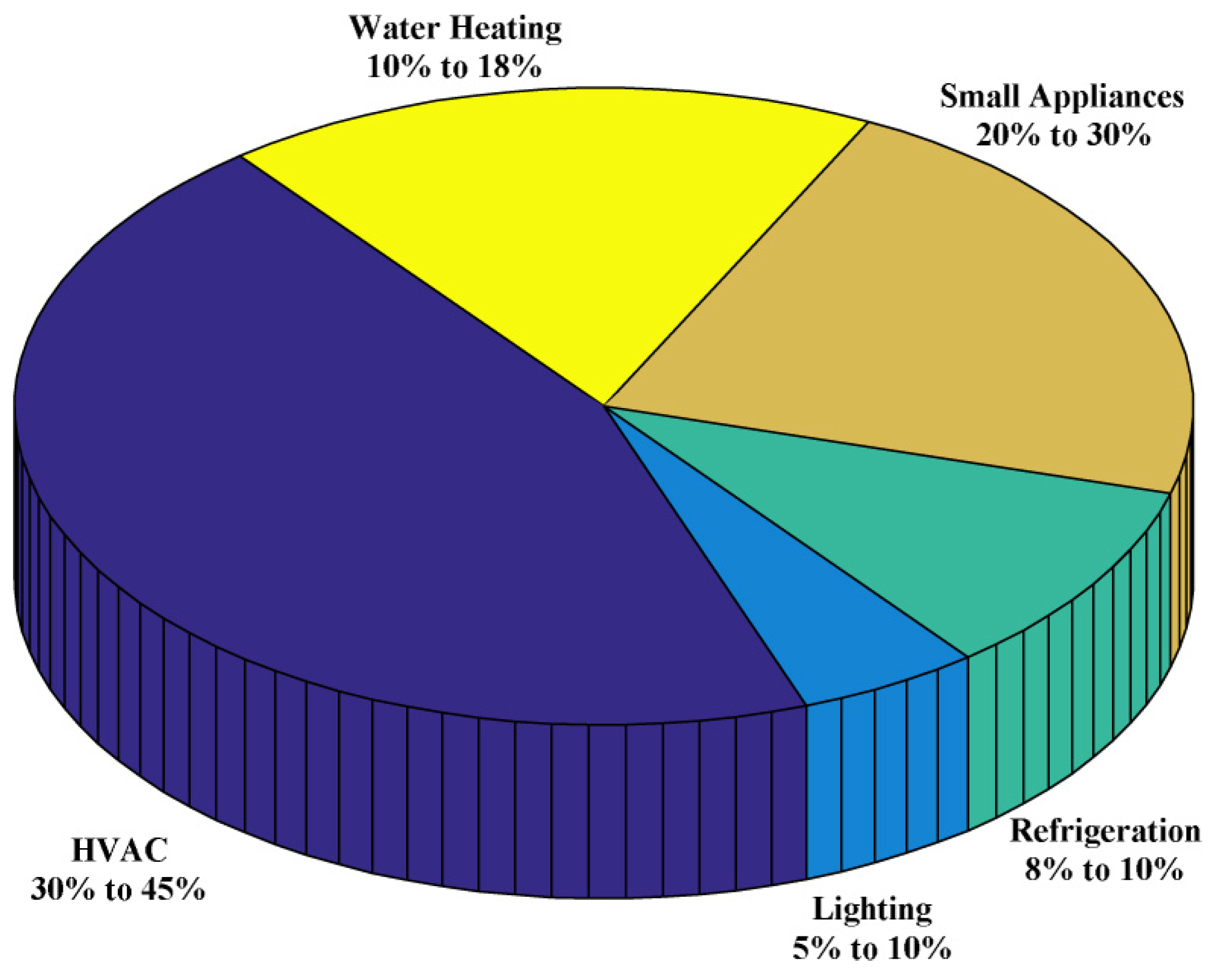
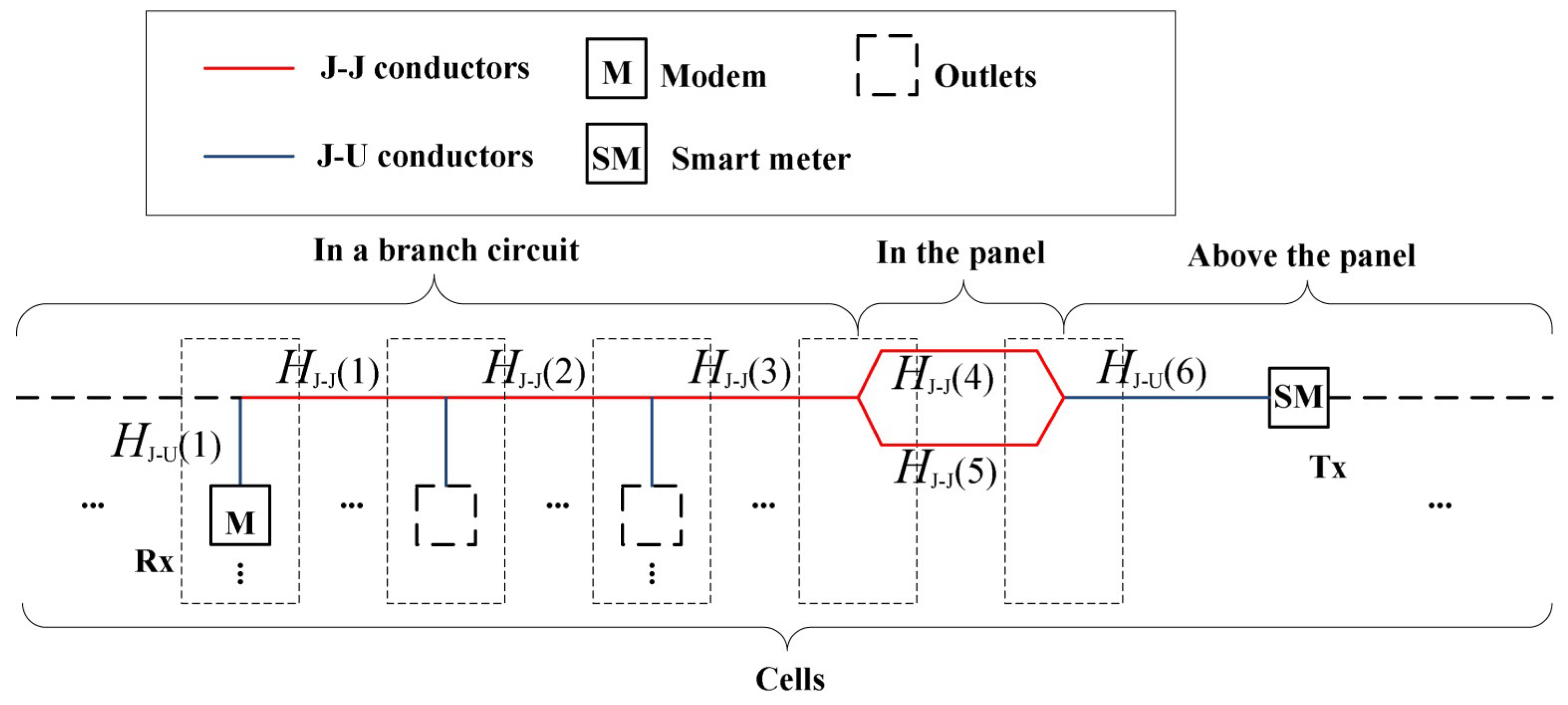
The third part of the topology is the branch circuits which are classified as either individual, lighting or small appliance (SA) circuits. AWG 6, 8, 10, 12 and 14 conductors are used in the model corresponding to 50, 40, 30, 20 and 15 A branch circuits, respectively. An individual circuit (single or split-phase), supports one appliance which typically has high power consumption. Split-phase circuits are used for high power appliances such as a range, range top, washing machine, dryer, or water heater that are above 2000 VA. A single-phase circuit supports appliances with a relatively low average power, but large initial power may be needed to start internal motors. Lighting and SA circuits have multiple outlets. Modems are connected to outlets to enable communications and provide information on the associated devices.
2.2. Branch Circuits and the Topology Above the Panel
The per unit length (p.u.l.) resistance
R, inductance
L, conductance
G and capacitance
C of conductors are considered first. These parameters are determined by the physical properties of conductors [
26] including the material (copper or aluminum), the number and diameter of conductors in cables and the number of strands, and the material and thickness of the conductor insulation. The p.u.l. resistance of a conductor is [
27]
where
r is the radius of the conductor,
is the conductivity,
is the skin depth,
is the magnetic permeability and
f is the frequency. For copper or aluminum,
is equal to the vacuum magnetic permeability
H/m. The conductivity
is the reciprocal to the resistivity
so that
, which is
for copper, and
for aluminum [
26]. For simplicity, frequency dependent parameters are abbreviated such that
R represents
. For a pair of conductors, the inductance (in the differential mode) is
where
is the inner self inductance,
is the outer self inductance, and
M is the mutual inductance. If
, then
[
28]. When
, for a circular conductor
The p.u.l. outer self inductance of a conductor is
where
l is the length of the conductor. The p.u.l. mutual inductance is
where
d is the distance between the conductors. In a four-conductor cable, two conductors can be in adjacent or diagonal positions [
19] with a difference in
d of
. If the two conductors have equal length, and
l is much greater than
r and
d, then
The p.u.l. capacitance and conductance satisfy
and
[
27]. The dielectric constant is
, where
F/m is the vacuum dielectric constant, and
is the relative dielectric constant which is 2.3 for AWG 2/0 to 3 conductors (polyethelene) and 2.55 for AWG 4 to 14 conductors (nylon polyamide). For conductors with multiple strands (e.g., 7 strands for AWG 3 to 6, and 19 strands for AWG 2/0 and 4/0),
R is multiplied by a correction factor
[
27,
29]. The characteristic impedance
and propagation constant
are [
24]
where
. For each conductor, the end closer to the transmitter is the input, and the farther end is the output. The output impedance of a conductor
is determined by the impedance of all components at the output. For instance, if the conductor is between an outlet and appliance which is on, the appliance impedance is the output impedance. If the appliance is off or the outlet is open (i.e., no modem or appliance), then
= ∞. With
N parallel impedances
,
, …,
at the output
NEC recommends the length of a branch circuit should accommodate a maximum 3% voltage drop [
26]. For individual circuits, the voltage drop
of a conductor is [
30]
where
is the p.u.l. DC resistance of the conductor [
26]. The minimum length
is 6 ft [
31], and the maximum length
should be less than 100 ft. The maximum current
is 0.8 times the amperage rating of the corresponding circuit breaker.
can be obtained from (
7) considering the maximum voltage drop. For lighting and small appliance circuits [
22]
where
N is the number of outlets and
if the rated current of each outlet is 1.5 A [
26]. The farthest outlet from the circuit breaker corresponds to
, and
is the length of the conductor between outlets
n and
, or between outlet
N and the circuit breaker [
18], so
. NEC recommends that for a branch circuit, the distance from the circuit breaker to the closest outlet should not exceed 70 ft for an AWG 12 conductor (SA circuit), or 50 ft for an AWG 14 conductor (lighting circuit). The distance between outlets is 0 to 12 ft.
The input impedance of a conductor is [
32]
and this is used as the output impedance of other conductors. The transfer function (TF) of a conductor is the ratio of the voltage at the output
to the voltage at the input
given by [
18]
2.2.1. Appliance Modeling
Appliance impedances are the output impedances of the corresponding outlet conductors. The home appliances considered here are given in
Table 1 [
31]. They can be classified as resistive, reactive or linear periodically time varying (LPTV) (types 1 to 3, respectively) [
25]. LPTV appliances have either commuted (3-1) or harmonic (3-2) impedance variations. There are seven types of circuits (
a to
g), which are split phase individual circuits, single phase individual circuits, lighting circuits, kitchen SA circuits, bedroom, study and living room (BSL) SA circuits, laundry area SA circuits, and bathroom SA circuits.
is the power of an appliance and the impedance of the corresponding resistive load is
where
V for a single phase circuit and
V for a split phase circuit. The impedance of a reactive load is obtained from the parallel RLC circuit model [
25] as
where
is the resistance at resonance. The power factor
is between
and 1 for reactive loads. The quality factor
is an indication of frequency selectivity and is typically between 5 and 25. The resonant frequency
is between 25 kHz and 200 kHz [
33,
34]. LPTV loads have impedance variations caused by non-linear elements such as thyristors which can be obtained using the approach in [
25].
2.2.2. Secondary Transformer Modeling
In [
35], impedance measurements for secondary transformers with 10 kVA to 50 kVA capacities were given. These measurements (with no cables connected), show that the real and imaginary parts of the impedance,
and
respectively, are proportional to the frequency. The ratio of
to
is approximately constant between 5 kHz and 20 kHz. Thus, the impedance can be expressed as
where at 0 Hz,
is between 0 and 1
and
is 0
, and increase with frequency by
/kHz and
/kHz, respectively. Accurate transformer models can be obtained if the material and structure of the windings are known.
2.3. Topology Inside the Panel
The conductors in the panel are modeled differently from the rest of the topology. In branch circuits and the topology above the panel, the conductors are closely packed in cables and sealed by insulation. The length
l is far greater than the cross section dimensions
r and
d. In the panel, the conductors are further apart and the cross section can be either circular or rectangular. The latter type comprises bars and the bonding strap, which are not sealed, and the cross section dimensions are comparable to the lengths. The p.u.l. impedance of a conductor in the panel is
where
is the p.u.l. resistance. For circular conductors,
is the same as in branch circuits. For the rectangular case [
36]
where
W and
T are the width and thickness of the conductor, respectively. The imaginary part of
is
where
is the p.u.l. inductance. The inner self inductance is
where the outer self inductance
is the same as in the circular case. The corresponding TF is
The parameters of the rectangular conductors are summarized in
Table 2.
Circuit Breaker Modeling
Thermal magnetic breakers are widely used in North America and are referred to as normal breakers. In the past 20 years, advanced AFCI or GFCI breakers have been developed to provide fault current detection and protection [
37,
38,
39]. In [
23], circuit breakers with various ampere ratings were modeled, but only single-pole normal breakers were considered. In the following, both single-pole and double-pole normal and advanced circuit breakers are modeled.
Figure 5 shows the general model for a breaker. The normal breaker structure is shown on the left of the dashed line. It contains a bare copper wire, a bimetallic strip with copper and steel, and a single copper strip. For the bare copper conductor,
r is determined by the breaker amperage and
l is 2 in. The width and length of the strips are 0.5 and 1.75 in, respectively. In the main breaker, the thickness is
in while in branch circuit breakers it is
in. An AFCI or GFCI breaker includes the right part with coils and two conductors. One phase conductor of length 1.75 in connects the single copper strip to the corresponding branch circuit. The other is a neutral conductor of length 17.5 in which is between the branch circuit and the neutral bar. In an AFCI breaker, sensing coils T1 and T2 detect series and parallel arcing. A GFCI breaker only has a T2 coil to detect parallel arcing. A double-pole circuit breaker can be considered as two parallel single-pole breakers. For AFCI or GFCI double-pole breakers, three conductors are used and are monitored by the T1 and T2 coils. The impedance and transfer functions of the conductors within these breakers can be obtained using (
9) and (
10) or (
14) and (
17) with the parameters given above.


