Article

A Structural Design Concept for a Multi-Shell Blended Wing Body with Laminar Flow Control

1
Aeronautics Research Center Niedersachsen (NFL), TU Braunschweig, Hermann-Blenk-Straße 42, 38108 Braunschweig, Germany
2
Institute of Aircraft Design and Lightweight Structures, TU Braunschweig, Hermann-Blenk-Straße 35, 38108 Braunschweig, Germany
3
Institute of Structural Analysis, Leibniz University of Hannover, Appelstraße 9A, 30167 Hannover, Germany
*
Author to whom correspondence should be addressed.
Energies 2018, 11(2), 383; https://doi.org/10.3390/en11020383
Submission received: 15 December 2017 / Revised: 2 February 2018 / Accepted: 3 February 2018 / Published: 7 February 2018
(This article belongs to the Special Issue Towards a Transformation to Sustainable Aviation Systems)

Abstract

:
Static and fatigue analyses are presented for a new blended wing body (BWB) fuselage concept considering laminar flow control (LFC) by boundary layer suction in order to reduce the aerodynamic drag. BWB aircraft design concepts profit from a structurally beneficial distribution of lift and weight and allow a better utilization of interior space over conventional layouts. A structurally efficient design concept for the pressurized BWB cabin is a vaulted layout that is, however, aerodynamically disadvantageous. A suitable remedy is a multi-shell design concept with a separate outer skin. The synergetic combination of such a multi-shell BWB fuselage with a LFC via perforation of the outer skin to attain a drag reduction appears promising. In this work, two relevant structural design aspects are considered. First, a numerical model for a ribbed double-shell design of a fuselage segment is analyzed. Second, fatigue aspects of the perforation in the outer skin are investigated. A design making use of controlled fiber orientation is proposed for the perforated skin. The fatigue behavior is compared to perforation methods with conventional fiber topologies and to configurations without perforations.

1. Introduction

The research project “Energy System Transformation in Aviation (EWL)” has been initiated by the Aeronautics Research Centre Niedersachsen (NFL) in Germany with the aim of reducing CO2 emissions by developing new aircraft concepts and evaluation of new technologies. As a result of the project, the blended wing body (BWB) design concepts were identified as a promising technology path. BWB aircraft are a concept promising advantages in aerodynamic performance and a reduction of fuel consumption. Preliminary research shows the potential of unconventional aircraft with respect to environmental concerns and noise pollution [1]. Liebeck et al. [2] developed an efficient structural concept abandoning the constraint of a cylindrical pressure vessel of a conventional aircraft. The advantage of the new configuration is a reduction of the maximal bending stress due to the better distribution of the aerodynamic loads compared to a conventional tube and wing aircraft. A higher passenger acceptance of BWB cabins was also identified in [3] as an advantage.
The structural layout of non-cylindrical fuselages is an aspect of aircraft design that remains under research. Alternative designs featuring multiple intersecting partial cylinders for the pressure skin are referred to as “multi-bubble” designs. Mukhopadhyay [2,3] and Mukhopadhyay et al. [4] presented structural analysis of different concepts of non-conventional cross sections. They performed preliminary studies on multi-bubble fuselages with two different design approaches: vaulted sandwich shell and flat sandwich shell. These studies found that the multi-bubble vaulted approach leads to a membrane stress dominated load state and, therefore, a light weight design. However, the multi-bubble design is not suitable for forming the aerodynamic profile of the BWB-design and a double shell concept with an aerodynamic outer shell is required. For this reason a double shell design is envisaged here.
Research on laminar flow control (LFC) began in the 1930s and became more important during the energy crisis in the 1970s because of the potential aerodynamic performance benefits for commercial aircraft [5]. The boundary layer flow on today’s large aircraft is turbulent at almost the entire wetted surface. This results in viscous drag five to ten times larger than that of laminar boundary layers. While for unswept wings at low Reynolds numbers, laminar flow can be achieved by a properly designed pressure distribution, high Reynolds numbers, especially in combination with swept wings, require active flow control to keep the boundary layer laminar. Sucking the part of the boundary layer near the wall through the porous skin into the wing dampens aerodynamic instabilities and prevents transition from laminar to turbulent flow. Figure 1 from [6] presents the concepts of natural laminar flow (NLF), full-chord laminar flow control (LFC) and hybrid laminar flow (HLFC), which integrates the two previous concepts. The diagram shows a schematic of the three concepts with the corresponding surface pressure coefficient ( C P ) versus chordwise extent (x/c).
In most studies, the effect of LFC on aircraft wings was investigated. Since for BWB design the wetted surface of the fuselage is substantial, the utility of Fuselage-LFC was investigated in the EWL project. Results show that for a conventional tube and wing design drag could be reduced to one fourth compared to the fully turbulent fuselage by using suction from near the nose to the beginning of the tailcone [7]. For the BWB design under consideration here, the Fuselage-LFC can be advantageously integrated into the double shell concept. The inner skin contains the interior pressure, while LFC occurs via the perforated outer skin. The plenum between the inner and outer skin can house ductwork to divert the ingested air to the propulsion system.
In the EWL project, new technologies were evaluated and combined in order to reduce fuel consumption and CO2 emission of aircraft. A new long-range BWB design concept was developed considering the impacts of different technologies together, see [8]. The developed design in the EWL project forms the basis for the structural analysis presented here. A summary of the specifications is listed in Table 1.
The first part of this paper presents a structural analysis of a composite multi-bubble fuselage segment for a BWB aircraft. Since only a preliminary design study is intended here, only a partial model truncated in longitudinal direction is considered. Section forces in longitudinal direction are neglected and aerodynamic loads are represented in a simplified manner. Based on the suggested cabin geometry from [4,5], a multi-bubble double skin hull segment was created using Python scripting for Abaqus/CAE® (Dassault Systèmes HQ, 78140 Vélizy-Villacoublay, France) to allow automatic model generation. The developed tool provides the possibility to parameterize the geometrical and stiffness properties of the BWB fuselage section under consideration here. Different structural configurations and laminate layups are investigated.
In the second part of the work the different fiber topologies in conjunction with the perforation hole are investigated for their on fatigue behavior. Three fiber topologies for the outer skin are taken into account: perforation with controlled fiber placement (CFP), perforated unidirectional and unperforated. CFP refers to a fiber topology were uninterrupted fibers are directed around the perforation [9]. On the contrary, perforated unidirectional refers to a topology obtained, for example, by drilling the perforation holes. The effect of CFP on orientation, fiber volume content, effective strength and effective stiffness is considered. The analysis is performed on micromodels loaded in such a manner that it is consistent with results obtained from the fuselage-model in critical a location. The load amplitude spectrum is a simplified version of the Transport WIng STandard (TWIST) spectrum [10]. A recently developed fatigue damage model (FDM) [11,12] is utilized for the analysis and load sequence effects are taken into account. Although the exact load sequence is unknown, the sequence dependence is exploited by exemplary studies of assumed increasing (Low–High) and decreasing (High–Low) load amplitudes from the spectrum.

2. Fuselage Segment Model

For the intended purpose of this work, that is, a preliminary design study, the fuselage is represented by a segment of a longitudinal length of 5 m and a lateral width of 15 m. No particular boundary conditions are applied at the front and back section plane of the segment, thus neglecting any section forces transmitted in longitudinal direction.

2.1. Structural Components

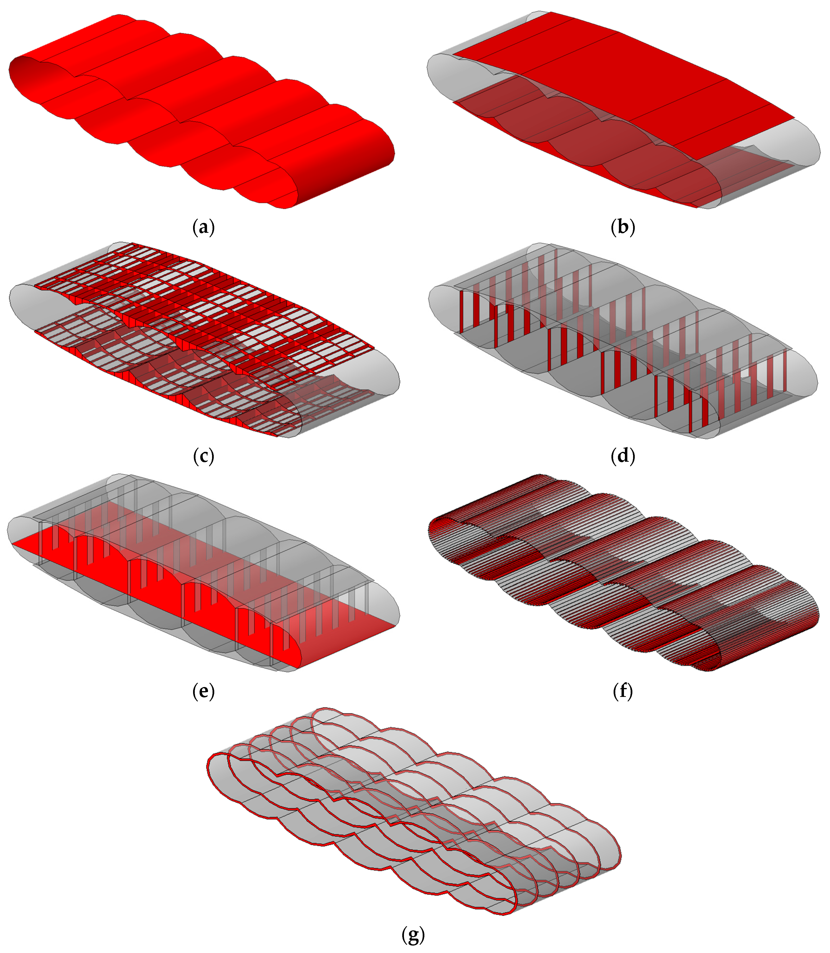
Based on the multi-bubble concepts taken from [13,14], a first shell is generated with seven bubbles corresponding to the BWB overall design with seven engines presented in [8]. The middle three bubbles are identical with a diameter of 3.7 m. The diameter of the two outer cylinders is decreased in order to adjust the aerodynamic shape of the wing. Figure 2 shows the geometry of the cross section in the generated multi-bubble cabin. The proposed layout is able to include 20 to 24 seats in on row, see [4,5]. The generated 3D cabin-skin is presented in Figure 3a.
The vaulted shape of the inner skin is dictated by the requirement to withstand the cabin pressure. It is, however, not optimal for the aerodynamic purposes and, thus, requires a separate outer skin see Figure 3b. The outer skin contributes to the stiffness with respect to the bending moment exerted by the wing forces and experiences according stress. Buckling instability in the outer- and cabin-skin is prevented by stiffening the thin skin with frames, stringers, chord- and span-ribs.
A cross ribbed design was adopted to join the inner and outer skin, see Figure 3c. Compared to a honeycomb core, the crossed ribbed structure is lighter [6] and its geometry and laminate layup can be optimized. The number of the ribs and their separation distances are parameterized in the model generator tool.
High stress concentrations are expected at the seams of the bubbles [15]. Structural elements are required in order to join the lower and upper sides to the cabin-skin. At the intersection of two cylindrical bubble sections they are joined to vertical walls in the cabin. The vertical walls can be designed in a close or open configuration. From a structural point of view, closed bubbles with continuous walls will have a smoother stress distribution between the sections. However, interrupted walls, see Figure 3d, allow for interior flexibility, passenger freedom of movement and fast evacuation.
The floor is spurted on the walls and the cabin-skin as shown in Figure 3e. Sandwich floor panels with honeycomb core are considered in the finite element model. A reasonable stiffening concept for the inner skin employs I-, Z- or omega-section stringers. In this work, the stringers are simplified to blades perpendicular to the curved cabin-skin. The stringers are distributed on the curved cabin-skin, see Figure 3f. Curved composite frames on the inner skin are modelled in order to divide the fuselage into multiple parts in chordwise direction, see Figure 3g. A high bending moment is expected in the span wise direction due to the wide form of the BWB fuselage. Therefore it appears pertinent to use the frames to support this load. The frames are represented in simplified form by blades perpendicular to the curved cabin-skin.

2.2. Material

An advantage of composite material based structural designs is the ability to affect the stiffness and strength of the fiber-reinforced laminate by the stacking sequence. In this work, all plies are assumed to be IM7-8552 carbon-epoxy. For floor and interior walls core honeycomb HexWeb® CRIII (Hexcel Corporation, Stamford, CT, USA) is assumed. The mechanical properties of the materials are taken from [16,17].

2.3. Loads and Boundary Conditions for the Static Analysis

The static stress analysis considers four types of loadings on the fuselage section. A 2.5 g (where g is the acceleration due to gravity) maneuver at maximum take-off weight is considered as bending moment from the wings as well as the lift load on the upper part of the outer skin. Internal pressure is applied on the cabin skin and mid-deck floor loading at 2.5 g is taken into account. The loads were multiplied by a safety factor of 1.5 to generate the design loads (ultimate loads). According to the works [6,13], an internal pressure of 0.128 N/mm2 is assumed including all safety factors. The internal pressure loads are applied on the interior surface of cabins as a uniform pressure as represented in Figure 4. The applied floor pressure includes the weight of passengers, cargo, systems and fuel and it is assumed to be 0.00431 N/mm2 at the loading case 2.5 g maneuver according to [6,13].
The aerodynamic loads for the long range considered BWB aircraft are estimated based on different design results corresponding to different technology scenarios. The results of the load cases are calculated using the methods developed in [8]. The loads are provided for 80 sections along the span-wise axis of the aircraft. The forces related to wings (areas which are outside the fuselage) are multiplied with their distance to the fuselage edge in order to calculate their bending moments at the fuselage edge. The resultant moments are assumed to be distributed uniformly along the fuselage edges. The equivalent moments for the 5-m segment are determined and applied on two reference points (RF1 and RF2) as shown in Figure 4. The reference nodes are located on the cabin sides and coupled to the nodes of the outer skin using kinematic coupling constraints. The aerodynamic lift at the outer skin is considered as uniform pressure at the outer surface and included in the analysis. Fixed boundary conditions in the vertical direction were assumed at both reference points where one of the reference points was also fixed in the horizontal direction. Section forces acting on the front and back section planes are neglected in the analysis.

2.4. Static Failure Criterion

The Hashin failure criterion of Abaqus® (Dassault Systèmes HQ, 78140 Vélizy-Villacoublay, France) is used to assess failure initiation for fiber-reinforced composite shells, see [18]. Hashin’s theory [19,20] distinguishes between four different failure initiation modes: fiber tension; fiber compression; matrix tension, and; matrix compression. Four output variables are provided by the simulation to indicate the failure index for each damage mode. An index of less than 1 indicates that the criterion is not satisfied and no damage is initiated in the material. The safety margin is ensured by 50% excess load imposed on the model. Therefore, a value of 1 or higher indicates that at this point the safety margin is not respected. The stress analysis on the fuselage model does not consider stress concentrations due to the perforation in the outer skin. Thus, failure in the outer skin cannot be detected in this model.

3. Micro Model for the Perforated Outer Skin

One aspect of the analysis of the effect of fatigue loading on the perforated holes is the controlled fiber placement of the fibers around the holes. Results from [21] show that the effective properties of the plates with the hole are generally improved when the fibers are curved around the hole, rather than interrupted by the hole. CFP can substantially mitigate the weakening effect of the hole, both with respect to strength and stiffness. However, in cases with high compressive loading situations, it has been seen that the CFP did not bring about any improvements and also reduced the compressive strengths [21,22]. Figure 5 represents the CFP for perforated holes for a rectangular pattern based perforations. In Figure 5, the basic geometry perforated skin is shown. Here, the diameter of the hole is 0.24 mm and the spacing between the perforations amounts to 1.00 mm in both directions.

3.1. Fiber Placement

Fibers are assumed to follow a cosine function in the vicinity of the hole, such that a greater curvature is seen near the hole and fibers further away from the perforation remain straight. The fiber orientation due to CFP is described by Equation (1). The total fiber volume content of any given x = const . section plane is constant at 60% with respect to the interval from y = 0 to y = 0.5   mm . The x / y -plane is split into a compressed and undisturbed segment. The vertical extend of the compressed segment is defined so that the maximum geometrically possible fiber volume is attained at the left edge, see Figure 6. This is based on the presumption that in manufacturing the CFP would be implemented via a displacement of the fibers by, for example, pins or similar implements. The topmost segment of the 0°-ply, and the right most segment of the 90°-ply, is filled by undisturbed fibers. The unshaded fish-eye region in Figure 6a, is filled by a pure matrix region in the model. The fiber angle, Equation (2), was obtained by differentiating Equation (1). There, the symbols x and y refer to the horizontal and vertical position with respect to the origin at the hole center. The symbol y 0 denotes the vertical position of a particular fiber at x = 0.50 .
f [ x , y 0 ] = y 0 + 0.25   ( 1 y 0 ) ( 1 + cos [ π   x 2 ] )
α [ x , y ] =   1.5708   ( 1 + 1   y ) sin [ π   x 2 ] 3 + 1   cos [ 1.5708   x ]
As depicted in Figure 6, a quarter model with appropriate symmetry constraints is employed for the micro-mechanical model. Because thickness and perforation spacing are of comparable magnitude, a 3D-solid discretization by eight-node fully integrated solid elements is used for the micro model as shown in Figure 7a. It has to be noted that the chosen fiber orientation results in a pure-matrix region as shown in Figure 6a. To facilitate the model generation, the small pure-matrix pockets indicated by blue region in Figure 7b, were omitted. The stiffness in those pockets is very low in comparison to the reinforced regions.

3.2. Variation in Material Properties

As apparent from Figure 6b the change in fiber volume content φ , is substantial and strength and stiffness parameters cannot be considered constant. The volume fraction along the left edge of the micro model approaches the maximum fiber volume content that is geometrically permissible in a square based packing of fibers in a composite, i.e., φ m a x = 0.91 . On the right edge the fiber volume content is taken to be 0.6 (default volume fraction of IM7 [16]). This causes the stiffness as well as the consequent strength parameters to be different in the model. Therefore, the stiffnesses in the longitudinal and transverse directions are approximated by the Chamis mixture theory [23]. A similar method of approximation was also used in determine the Poisson’s ratio, ν 12 . However, ν 23 , the out-of-plane Poisson’s ratio is set to the Poisson’s ratio of the matrix, which in this case set to be 0.4. As transverse isotropy is assumed, the out-of-plane modulus, E 23 can be calculated using the following equation:
E 23 = E 22 2 ( 1 + 23 )
Since only a preliminary study is intended here, a linear rule of mixture for the strength in fiber direction was assumed with respect to φ . In transverse direction the strengths were assumed constant as shown in Figure 8. It can be seen that the homogenization of longitudinal strength was carried out based on the known strengths for φ = 0.6 and the fiber strength (solid line), rather than interpolating to zero (dashed line) as shown in Figure 8a. In the direction transverse to the fiber and for the shear strength no dependence on φ was considered, as represented in Figure 8b. The blue shaded region marks the range of φ in the model. As indicated in Figure 8, the parameters X t ( φ ) / X c ( φ ) , indicate the corresponding tensile/compressive strengths in fiber direction. Similarly, the parameters Y t ( φ ) / Y c ( φ ) , indicate the corresponding strength parameters in transverse direction and S ( φ ) denotes the shear strengths.

3.3. Simplified Layup and Consequent Extensional Stiffness Matrix

With the approximation procedures defined in Section 3.1 and Section 3.2 the representation of the CFP in the micromodel proved to be complicated for the [45/0/-45/90/45/90/-45/90]s laminate layup used in the global model of the fuselage section. As a substitute, a layup of equivalent diagonal coefficients A11 and A22 in the extensional stiffness of the laminate was devised for the micro-mechanical model used in the fatigue calculations. The simplified layup comprises 0° and 90° plies. In this simplification approach, the individual thickness t, for 0° and 90° plies were determined so that the A11 and A22 entries in the extensional stiffness matrix for the complex layup used in the global fuselage laminate model and the simplified laminate configuration in the micromodel are the same.
For determining the individual thicknesses for all the three cases, finite element method (FEM) based stress analyses were performed on the individual plies (oriented in 0° and 90°) of unit length. The reaction forces in both the plies were computed and later correlated to the whole laminate using the extensional matrix and resultant reaction forces. This leads to two sets of linear equations, when solved provided the thickness values required to match the A11 and A22 entries in the global extensional matrix A. Based on the above procedure, the newly calculated thickness for all the 3 cases of micro model in comparison to the global fuselage configuration are shown in Table 2.
As shown in Table 2, the global fuselage laminate has a constant thickness of 0.125 mm for all the plies, whereas the simplified micro model has different thickness for the 0° and 90° plies. It can be seen that the perforated micro model with the CFP, required a reduced thickness, particularly for the 90° plies, to attain the same stiffness that of the global model when compared to the same laminate configuration without CFP and is more comparable to the micro model without perforation [21]. In comparison to the global fuselage laminate configuration, due to the particular stacking sequence in the simplified laminate configuration, not all entries in the extensional stiffness and bending matrix could be matched. This shortcoming seems acceptable for the purpose of a preliminary design study in the present work, however, it is intended to be properly addressed in future works.

4. Static Analysis

In this section, strength and buckling analyses are performed for the previously described fuselage segment model. Different configurations are evaluated by stress analysis under the preliminary flight loads. In the first analysis step, two different configurations are considered for the ribbed double-skin fuselage. The first configuration contains 34 chord-ribs, five span-ribs, five frames and six walls between each two adjacent bubbles. Whereas, in the second configuration, the distances between the span-ribs and distances between the frames are decreased from 1 m to 0.5 m which increases the number of each of them from five to 10. Stress analyses are performed for both configurations applying the load case 2.5 g maneuver at maximum takeoff weight. Figure 9 represents the stress distributions in the span wise direction and the deflections for the fuselage section under the critical ultimate loads.
Figure 9a,b show a decrease in the maximal stress of 36% by increasing the number of the frames and span ribs from 5 to 10 in the second configuration. The deflection in the center of the fuselage is decreased from 421 mm in configuration 1 to 257 mm in configuration 2. Due to the internal pressure on the cabin-skin, high-stress concentrations can be observed in the junction between walls and cabin-skin. Figure 10 represents the failed elements. Matrix failure under compression and tension are observed there. A redesign is required for these local areas. However, considering the main objective of the present work is the definition of a basic structural concept rather than the individual component design of fuselage, the required redesign process is not addressed here.
Buckling analysis is an important aspect in the design of thin walled structures. In addition to strength and stiffness requirements the thin composite structures must be structurally stable. Due to the preliminary character of the structural design under consideration here buckling is investigated in this work by linear buckling analysis
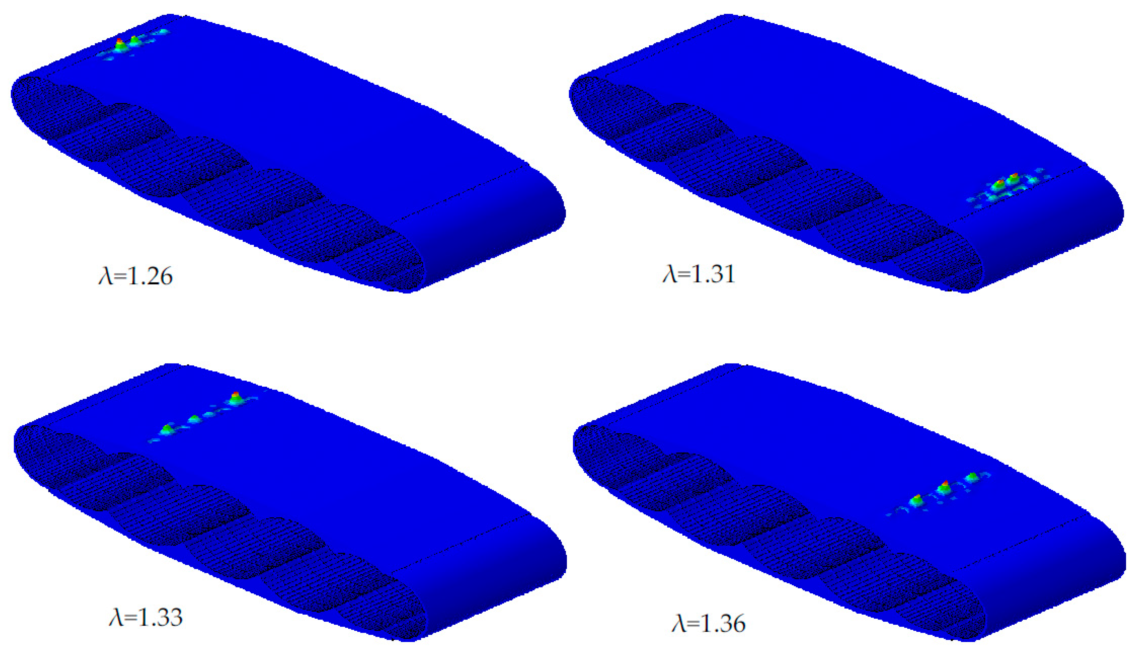
For the linear buckling problem the first four eigenvalues and eigenshapes are presented. The lowest eigenvalue is associated with buckling, if the buckling load is: F buck = λ F ref and λ < 1 buckling, while λ > 1 safe. The buckling modes are presented in Figure 11 and Figure 12, where local buckling shapes can be observed at the two sides of the outer skin (load introduction areas) and between the rips at the upper pressure side where buckling is expected.
Therefore, at these smaller areas in Figure 11 local stiffening is needed, which increases the buckling strength and has no substantial impact on the weight. Another approach is a generally narrower stiffening scheme, as in Figure 12, which shows no buckling problems.
The fuselage weight per unit floor area is determined for both configurations. The estimated weight for the first configuration is 34.63 kg/m2 with five span-ribs and five frames. When doubling the number of span-ribs and frames in the second configuration, the weight was increased to 38.68 kg/m2. Table 3 presents the comparison between the two configurations.
The maximal bending stress in a BWB aircraft is expected to occur in the span wise direction, the influence of other structural components is studied in the second step of this section. A parameter study is carried out for different thicknesses of span-ribs and two different laminate layups of the outer skin. The first configuration with five frames is chosen for these studies. In the first study, the span-ribs’ thickness is increased from 2 mm to 5 mm. The resulting weight, max. deflection, max. stress and critical areas are presented in Table 4. The analysis results show a stress reduction of 19% by increasing the thickness from 2 mm to 5 mm. Where the weight per unit floor area increases from 33.91 kg/m2 to 36.06 kg/m2. Compared to the first analysis of configurations 1 and 2, the increasing of the span-ribs’ thickness reduced the main deflection in the span wise direction of 8.20% by increasing of 6.34% of the weight. On the other hand, the increasing of the number of the frames reduced the main deflection of 38.95% with a weight increasing of 11.70%. The second parameter analysis presents the influence of laminate layups for the outer skin on the strength analysis. For this purpose, three different layups are introduced for the outer skin, where the first layup [45/0/-45/90/45/90/-45/90]s is assumed in configuration 1. The calculated stress, deflection and weight are presented in Table 5.

5. Fatigue Analysis

Based on the static results for the load factor n = 1 g a point on the centerline of the outer skin was chosen for the fatigue analysis. This point was deemed representative, because in a large area around it similarly high strain occurs. Regions of even higher, but very localized, strain near joints were not considered, since in a practical design those regions would not be weakened by perforation. The representative points (indicated by highlighted regions in red in Figure 13) are seen to have a high value of the strain component in 0° direction, ε ¯ 11   = 2.96 × 10 4 , but negligible strain ε ¯ 22 . The strain component ε ¯ 11 obtained from the fuselage model manifests itself on the micromodel as the average strain [24], that is:
ε ¯ 11 =   1 V μ V μ   ε 11 μ ( x , y , z )   · d V .
In Equation (4), ε ¯ 11 is the (homogenized) macroscopic strain observed in the fuselage model, ε 11 μ is the locally inhomogeneous strain in the micro model and V μ is the Volume of the micro model. Loading conditions for the micro model that are equivalent to the global strain component ε ¯ 11 can be obtained by displacing the appropriate boundary in the micromodel by the value specified in Equation (5). There, U 1 is the displacement in span wise-direction and L is the length of the micro model.
U 1 = ε ¯ 11 · L .
A corresponding expression exists for U 2 , however, in the present case ε ¯ 22 is negligible in the critical point and, therefore U 2 = 0.

5.1. Fatigue Damage Model (FDM)

In case of high performance applications such as rotor blades for wind turbines and aircraft, fiber-reinforced plastics (FRPs) based components are not only subjected to just static loads but also to stochastic cyclic loads during their life time. Therefore, effective fatigue predictions in these components have become a matter of priority and in the last decade different modelling techniques have been investigated. Depending on the accuracy of the damage prediction and the physical form of damage, these fatigue models can be classified into three groups: fatigue life models, phenomenological models and progressive damage models [25]. A physically based fatigue damage model recently developed [11,12] addresses several disadvantages of many of the models currently used for composite materials. The model (denoted in the following as FDM) is capable to consider stress redistributions and load sequence effects and is used as the basis for the fatigue studies in this paper. Furthermore the FDM is able to accumulate redistributions and load sequence effects, and is able to describe the nonlinear fatigue damage accumulation [26], which is typical for FRPs [27]. The original model as described in [11,12] is based on the classical laminate theory (CLT), such that it is capable to analyze damage states ply-wise and also works on the basis of fracture-mode depended theory of Puck [28,29]. Based on the material orientation (longitudinal and transverse to fiber direction) and the applied load (e.g., tension, compression and shear) degradation factors are introduced for both strength and stiffness degradations. Figure 14 represents the layout of the FDM and as depicted, it comprises two parts, a continuous and a discontinuous part. In the discontinuous part, the material degradation is calculated under static loading using Puck’s criterion for static failure. Once the quasi-static analysis is done, the continuous part is initiated, calculating the material degradation as a result of cyclic loading.
The main feature of the FDM is the energy-based hypothesis by Pfanner [30], which was originally developed for reinforced concrete. This hypothesis equalizes the energy dissipated during fatigue loading to that of the energy in the quasi-static loading and that the damage state due to degradation in mechanical properties such as stiffness and strength not only depend on the amount of energy dissipated but also on the duration and amplitude of loading in the structure. Due to this energy-based approach it is possible to consider block loadings in the analysis. In particular highly dynamic stressed structures can thereby be calculated in an efficient manner. The method was partially validated with the results from the OptiDAT-Data bank [31].
However analysis of more complicated situations involving three-dimensional (3D) stress states, the CLT based FDM is no longer applicable and stresses in all directions have to be considered. Recently, Madhusoodanan et al. [26] extended the FDM [11,12] to take into account the stresses and degradations for 3D. In the present work, the FDM based on the 3D framework is employed.

5.2. Load Spectrum and Load Ratios

Several suggestions for the appropriate load spectra for aircraft can be found from literature [10,32,33,34]. By definition, a spectrum is ordered by frequency, and the sequence of the amplitude cannot be restored from it. In the present case the load sequence is of importance, however, since the employed fatigue model considers sequence effects. As a consequence, a precise prediction regarding the fatigue life requires flight by flight load block definitions and cannot be made based on a spectrum alone. However, due to the large computational effort required for the flight by flight analysis, this method is not used in the present work. Instead, some approximate results are obtained from an assumed load sequence, that is, sorting the load blocks obtained from the spectrum in ascending (Low to High or Lo–Hi) or descending (High to Low or Hi–Lo) order. Among the three load spectrums [10,32,33,34], the fatigue predictions using simplified flight-simulations are found to yield good results for residual crack growth in aircraft components [33]. As an alternative, the fatigue based strength degradation in the outer skin is analyzed by using a separate Hi-Lo and Lo-Hi simple block loading spectrums.
A realistic fatigue loading sequence is not readily available for conceptual BWB aircraft. In the fatigue analyses using the FDM, load sequences as used in experimental testing of aircraft are applied as virtual tests. The load spectrum defined for the so called TWIST [10] is considered to be appropriate, however, only a reduced version of the TWIST sequence shown in Figure 15 is used for fatigue calculation. The corresponding fatigue data for each load block can be found in Table 6. Only load ratios, R = 0 and above R = 0.63 are considered for the present work. This is due to the fact that the employed FDM has not been properly validated for the reversible loading ratios, R < 0.

5.3. Determination of Appropriate S-N Curves

The key components required for the assessment under fatigue failure are the S-N curves. These curves relate the number of load cycles to failure to a given applied maximum stress. Furthermore, they also serve as the abort criterion for the FDM. The characteristic of these curves depend strongly on the fiber orientations and the applied stress ratio [35]. Experimental methods to determine the individual S-N curves are cumbersome and not cost-effective. As a result, numerical methods are usually employed for the effective prediction of the different S-N curves. One appropriate method of numerical approximation is the Modified Fatigue Strength Ratio by Kawai [36]. It is able to predict further S-N curves based on virtual test results for the same failure mode. This methodology of the approximation is explained in the following steps. Firstly, a so called fatigue strength ratio, ψ can be defined as:
ψ = σ m a x R t = σ a + σ m R t .
In Equation (6), the parameters, σ m a x , R t , σ a , σ m are the corresponding fatigue strength, the static strength, the stress amplitude and the mean stress. Figure 16 describes the characteristics of a typical fatigue loading and also the relationships among these values. It should be noted that for ψ = 1 , the material is considered to have failed.
Based on the fatigue strength ratio, ψ the modified fatigue strength ratio, 𝛹 can be represented using Equation (7). In Equation (7), the parameter R, corresponds to the stress ratio and be expressed in Equation (8).
Ψ = σ a R t σ m = 0.5 · σ m a x · ( 1 R ) R t 0.5 · σ m a x · ( 1 + R ) ,
R = σ m i n σ m a x = σ a σ m σ a + σ m .
For the case of a fully tension-compression based reversible loading condition ( R = 1 ), Ψ will be equal to ψ. In order to describe a similar mean stress variation as in the Goodman diagram [37], a non-dimensional scalar, Ψ has been introduced. With the help of Equations (6)–(8), it is possible to estimate any S-N curves based on the respective failure mode. Using the Kawai model, the S/N curve mapping procedure can be said to comprise of three main steps, as stated in [36].
Some complication arises from the circumstance that no S-N curves are readily available for IM7-8552. Hussain et al. [38] reports a constant amplitude fatigue tests to determine S-N curves for unidirectional carbon FRP (CFRP)-plies of various fiber orientations and stress ratios. The material properties of CFRP used in [38] was found to be similar to the one used in the present work and as a result the basis S-N curves were adopted from the same reference. With the help of Basquin’s law [39], the experimental data were fitted using Equation (9). Here, the parameter N f corresponds to the number of load cycles to failure, n , for a corresponding maximum stress, σ m a x ( R e x p ) . The fitting values σ f ' and b depend on the fiber angle and the applied stress ratio. For this work experimental S-N curves with a stress ratio of R e x p = 0.1 is chosen for the 0° and 90° plies.
σ m a x ( R e x p ) = σ f ' ( N f ) b .
Based on [36,40], the second step involves the derivation of a master modified fatigue strength ratio, Ψ * based on Equation (7). This relation depends on the number of load cycles and is directly related to the experimental parameters. This can be expressed as
Ψ * ( n ) = 0.5 · σ m a x ( R e x p ) ( n ) · ( 1 R e x p ) R t 0.5 · σ m a x ( R e x p ) ( n ) · ( 1 + R e x p ) .
In the last step, the approximated S-N curves are obtained by further combining the Equations (7) and (11). This relation is expressed in Equation (11). Based on the simplified TWIST load spectrum indicated in Figure 14, the mapping procedure has been used to determine S-N curves for both 0° and 90° plies in the simplified micro model. These curves are generated for several load ratios ranging from R = 0 to R = 0.63 as well as for different loading conditions, such as tension and compression, both in the longitudinal and transverse to fiber directions. Figure 17 represents the approximated S-N curves for the simplified TWIST spectrum for the 90° plies in the simplified micro model.
σ m a x * ( R n e w , n ) = 2 · R t · Ψ * ( 1 R n e w ) + ( 1 + R n e w ) · Ψ * .
In none of the micro models degradation in fiber direction of either strength or stiffness due to fatigue was observed. The longitudinal stress is well below the tensile strength of the composite and were found not lead to fatigue.
A varying degree of fatigue degradation was observed in the transverse fiber direction in both of the perforated micro models, see Figure 18. However, no degradation occurred in the unperforated micro model. The fiber topology without CFP leads to a higher longitudinal stress concentration near the hole, but showed only a very minor degree of transversal degradation. For the fiber topology with CFP the concentration of longitudinal stress near the hole was reduced. In fact, for this configuration the stress maximum occurred near the transition from the compacted to the undisturbed fibers, ca. at y = 0.45   mm in Figure 18b. The diversion of the longitudinal stress induced somewhat higher transversal stress. In turn, this caused the CFP micro model to accumulate more transversal degradation than the one without CFP.
As is apparent from Figure 18 the load sequence has little effect on the distribution of the transverse degradation. In both sequences, the load block with the highest amplitude (Load block V in Figure 15) caused essentially all degradation.
Substantial degradation was observed for the shear strength and stiffness. However, the lack of calibration data prevented the generation of R-ratio dependent shear S-N curves, limiting the accuracy of the predicted shear degradation.

6. Results and Conclusions

In this paper, a new structural design concept for a multi shell BWB fuselage with LFC has been developed in order to gain insight into the structural performance at the conceptual aircraft design stage. For this purpose, a new double shell design concept was modelled using a parametric Python tool. Different laminate thicknesses, layups and geometries were studied for their influence on the strength and buckling loads. Furthermore, the effect of different number of frames, span rib thicknesses and outer skin layups were considered. Weight, maximal stress, maximal deflection and failed areas are obtained and compared between the considered configurations. It was found that while the changes in the skin layups do not have a major impact (under 2%) on the maximum stress, the change in frame and rib distances from 1 m to 0.5 m has reduced the maximal stress to 36%. Furthermore the first eigenvalue in the linear buckling analysis is increased from 0.82 to 1.26. In the sensitivity study for the laminate thickness of the span-ribs, it was found that the maximal stress is decreased to 19% by increasing to thickness from 2 mm to 5 mm.
Three micromodels of equivalent membrane stiffness where investigated for their fatigue behavior. The respective micro models were for a perforation with CFP, a conventional perforation without CFP and an unperforated topology. The fatigue analysis used a simplified variant of the TWIST spectrum. In the fatigue model employed in the analysis sequence effects are taken in to account. Since the actual amplitude sequence is unknown, the TWIST amplitudes were applied in an assumed order: sorted by increasing and decreasing amplitude. The fatigue investigations did not indicate a clear advantage of a CFP micro-topology over a conventional interrupted fiber microstructure for the considered load situations. This is likely due to the particular loading scenario. Loads were insufficient to trigger fiber failure, a failure mode where the larger amount of uninterrupted fibers in the CFP microstructure would be advantageous. Only a single normal strain component was imposed on the micromodel and, thus, the applied strains were perfectly aligned with the rectangular grid pattern of the perforation. This circumstance might have further contributed to the favorable performance of the interrupted fiber micromodel by essentially unloading the interrupted fibers, negating any shear-lag load transfer from interrupted to continuous fibers. The CFP topology, on the other hand, suffers from degradation induced by shear due to the fiber axes being at an angle to the load axis.

Acknowledgments

The authors would like to acknowledge the support of ir. Eelco Jansen and would like to express their gratitude for his comments. The authors would also like to acknowledge the support of the Ministry for Science and Culture of Lower Saxony (Grant No. VWZN3177) for funding the research project “Energy System Transformation in Aviation” in the initiative “Niedersächsisches Vorab”.

Author Contributions

Majeed Bishara designed the new concept of the multi-bubble fuselage, coded the python tool to create the different configurations of the fuselage segments, carried out the FE-analyses on the global models, analyzed the results, and wrote the main part in Section 1, Section 2, Section 4 and Section 6. Peter Horst initiated and coordinated the work, gave valuable guidance, and reviewed the complete paper. Hinesh Madhusoodanan conducted the literature research on the fatigue topic, contributed to the development of the micro model for perforated outer skin (Section 3) and provided the extension of the FDM to the 3D framework used in the fatigue analysis (Section 5). The majority of the text in the development of micro model (Section 3) and certain parts of the text in the fatigue analysis (Section 5) were also edited and modified by him. Martin Brod carried out the fatigue analysis, contributed to the literature research, provided fatigue material parameters and S/N curves required for the load spectrum (Section 5). The majority of the text in the fatigue analysis (Section 5) were also edited and modified by him. Benedikt Daum developed the micro model for the perforated skin (Section 3), provided technical supervision and number of key suggestions in the work. Raimund Rolfes initiated the work, coordinated between the institutes and supervised the paper.

Conflicts of Interest

The authors declare no conflict of interest.

References

  1. Liebeck, R.; Page, M.; Rawdon, B. Blended-wing-body subsonic commercial transport. In Proceedings of the 36th AIAA Aerospace Sciences Meeting and Exhibit, Reno, NV, USA, 12–15 January 1998; American Institute of Aeronautics and Astronautics: Reston, VA, USA, 1998. [Google Scholar]
  2. Mukhopadhyay, V. Structural concepts study of non-circular fuselage configurations. In Proceedings of the SAE/AIAA World Aviation Congress, Los Angeles, CA, USA, 22–24 October 1996. [Google Scholar]
  3. Mukhopadhyay, V. Blended wing body (BWB) fuselage structural design for weight reduction. In Proceedings of the 46th AIAA/ASME/ASCE/AHS/ASC Structures, Structural Dynamics and Materials Conference, Austin, TX, USA, 18–21 April 2005; p. 2349. [Google Scholar]
  4. Mukhopadhyay, V.; Sobieszczanski-Sobieski, J.; Kosaka, I.; Quinn, G.; Charpentier, C. Analysis, Design and Optimization of Non-Cylindrical Fuselage for Blended-Wing-Body (BWB) Vehicle. J. Aircr. 2004, 41, 925–930. [Google Scholar] [CrossRef]
  5. Joslin, R.D. Aircraft laminar flow control. Annu. Rev. Fluid Mech. 1998, 30, 1–29. [Google Scholar] [CrossRef]
  6. Collier, F., Jr. An overview of recent subsonic laminar flow control flight experiments. In Proceedings of the 23rd Fluid Dynamics, Orlando, FL, USA, 6–9 July 1993; American Institute of Aeronautics and Astronautics: Reston, VA, USA, 1993. [Google Scholar]
  7. Beck, N.; Landa, T.; Seitz, A.; Boermans, L.; Liu, Y.; Radespiel, R. Drag Reduction by Laminar Flow Control. Energies 2018, 11, 252. [Google Scholar] [CrossRef]
  8. Liu, Y.; Elham, A.; Horst, P.; Hepperle, M. Exploring Vehicle Level Benefits of Revolutionary Technology Progress via Aircraft Design and Optimization. Energies 2018, 11, 166. [Google Scholar] [CrossRef]
  9. Marsh, G. Automating aerospace composite production with fibre placement. Reinf. Plast. 2011, 55, 32–37. [Google Scholar] [CrossRef]
  10. Schuetz, D.; Lowak, H.; De Jonge, J.B.; Schijve, J. A Standardized Load Sequence for Flight Simulation Tests on Transport Aircraft Wing Structures; LBF-Report FB-106; NLR-Report TR 73; National Aerospace Laboratory (NLR): Amsterdam, The Netherlands, 1973. [Google Scholar]
  11. Krueger, H. Ein Physikalisch Basiertes Ermüdungsschädigungsmodell zur Degradations-Berechnung von Faser-Kunststoff-Verbunden. Ph.D. Thesis, Institute of Structural Analysis, University of Hanover, Hannover, Germany, 2012. [Google Scholar]
  12. Krüger, H.; Rolfes, R. A physically based fatigue damage model for fibre-reinforced plastics under plane loading. Int. J. Fatigue 2015, 70, 241–251. [Google Scholar] [CrossRef]
  13. Der Voet, Z.V.; Geuskens, F.J.M.M.; Ahmed, T.J.; Van Eyben, B.N.; Beukers, A. Configuration of the Multibubble Pressure Cabin in Blended Wing Body Aircraft. J. Aircr. 2012, 49, 991–1007. [Google Scholar] [CrossRef]
  14. Geuskens, F.; Bergsma, O.K.; Koussios, S.; Beukers, A. Pressure Vessels & Pressure Cabins for Blended Wing Bodies. In Proceedings of the ICCM-17 17th International Conference on Composite Materials, Edinburgh, UK, 27–31 July 2009; Volume 27, pp. 1–12. [Google Scholar]
  15. Hansen, L.U.; Heinze, W.; Horst, P. Blended wing body structures in multidisciplinary pre-design. Struct. Multidiscip. Optim. 2008, 36, 93–106. [Google Scholar] [CrossRef]
  16. Kaddour, A.; Hinton, M.; Smith, P.; Li, S. Mechanical properties and details of composite laminates for the test cases used in the third world-wide failure exercise. J. Compos. Mater. 2013, 47, 2427–2442. [Google Scholar] [CrossRef]
  17. Hexcel Corporation. HexWeb® CR III Corrosion Resistant Specification Grade Aluminum Honeycomb; Product Data; Hexcel Corporation: Stamford, CT, USA, 2017. [Google Scholar]
  18. Hibbitt, K.; Sorensen. ABAQUS/Standard User’s Manual; Hibbitt; Karlsson & Sorensen: Johnston, RI, USA, 2001. [Google Scholar]
  19. Hashin, Z. Failure Criteria for Unidirectional Fiber Composites. J. Appl. Mech. ASME 1980, 47, 329–334. [Google Scholar] [CrossRef]
  20. Hashin, Z.; Rotem, A. A fatigue failure criterion for fiber reinforced materials. J. Compos. Mater. 1973, 7, 448–464. [Google Scholar] [CrossRef]
  21. Koricho, E.G.; Khomenko, A.; Fristedt, T.; Haq, M. Innovative tailored fibre placement technique for enhancd damage resistance in notched composites. Compos. Struct. 2015, 378–385. [Google Scholar] [CrossRef]
  22. Mattheij, P.; Gliesche, K.; Feltin, D. Tailored fibre placement—Mechanical properties and applications. J. Reinf. Plast. Compos. 1998, 17, 774–786. [Google Scholar] [CrossRef]
  23. Chamis, C.C. Mechanics of Composite Materials: Past, Present, and Future. J. Compos. Technol. Res. 1989, 11, 3–14. [Google Scholar]
  24. Dvorak, G.J. Elementary Concepts and Tools. In Micromechanics of Composite Materials; Springer: Berlin, Germany, 2013; pp. 35–77. [Google Scholar]
  25. Degrieck, J.; Van Paepegem, W. Fatigue damage modeling of fibre-reinforced composite materials. Appl. Mech. Rev. 2001, 54, 279–300. [Google Scholar] [CrossRef]
  26. Madhusoodanan, H.; Jansen, E.; Rolfes, R. Simulation of damage behavior in GFRPs in the very high cycle regime. In Proceedings of the VHCF7—Seventh International Conference on Very High Cycle Fatigue, Dresden, Germany, 3–5 July 2017. [Google Scholar]
  27. Reifsnider, K.L.; Jamison, R. Fracture of fatigue-loaded composite laminates. Int. J. Fatigue 1982, 4, 187–197. [Google Scholar] [CrossRef]
  28. Puck, A. Festigkeitsanalyse von Faser-Matrix-Laminaten: Modelle für Die Praxis; Hanser: Munich, Germany, 1996. [Google Scholar]
  29. Knops, M. Analysis of Failure in Fiber Polymer Laminates: The Theory of Alfred Puck; Springer Science & Business Media: Berlin, Germany, 2008. [Google Scholar]
  30. Pfanner, D. Zur Degradation von Stahlbetonbauteilen unter Ermüdungsbeanspruchung; VDI-Verlag: Düsseldorf, Germany, 2002. [Google Scholar]
  31. Nijssen, R.P.L. Optidat-Database Reference Document—The Knowledge Centre Wind Turbine Materials and Constructions; Delft University of Technology: Wieringerwerf, Germany, 2005. [Google Scholar]
  32. Schijve, J. The Accumulation of Fatigue Damage in Aircraft Materials and Structures; AGARDograph No. 157; National Aerospace Laboratory NLR: Amsterdam, The Netherlands, 1972. [Google Scholar]
  33. Schijve, J. Fatigue damage in aircraft structure, not wanted, but tolerated. Int. J. Fatigue 2009, 31, 998–1011. [Google Scholar] [CrossRef]
  34. Wanhill, R.J.H. Flight Simulation Fatigue Crack Growth Guidelines; No. 545; National Aerospace Laboratory NLR: Amsterdam, The Netherlands, 2001. [Google Scholar]
  35. El Kadi, H.; Ellyin, F. Effect of stress ratio on the fatigue of unidirectional glass fibre/epoxy composite laminae. Composites 1994, 25, 917–924. [Google Scholar] [CrossRef]
  36. Kawai, M. A phenomenological model for off-axis fatigue behavior of unidirectional polymer matrix composites under different stress ratios. Compos. Part A Appl. Sci. Manuf. 2004, 35, 955–963. [Google Scholar] [CrossRef]
  37. Goodman, J. Mechanics Applied to Engineering, 4th and enl. ed.; Longmans, Green and Co.: London, UK, 1904. [Google Scholar]
  38. Hussain, M.S.; Anilchandra, A.R.; Jagannathan, N.; Manjunatha, C.M. Fatigue life prediction of a unidirectional carbon fiber composite under off-axis spectrum loads using 3D constant life diagram. Mater. Perform. Charact. 2016, 5, 132–147. [Google Scholar] [CrossRef]
  39. Buch, A. Fatigue Strength Calculation; Trans Tech Publ: Zürich, Switzerland, 1988. [Google Scholar]
  40. Cuntze, R. Progress reached?—Lifetime Prediction for UD-materials by using S-N curves, Kawai’s Modified Fatigue Strength Ratio and Novel Haigh Diagrams. In Proceedings of the Simulation von Composites—Bereit für Industrie 4.0? Hamburg, Germany, 26–27 October 2016. [Google Scholar]
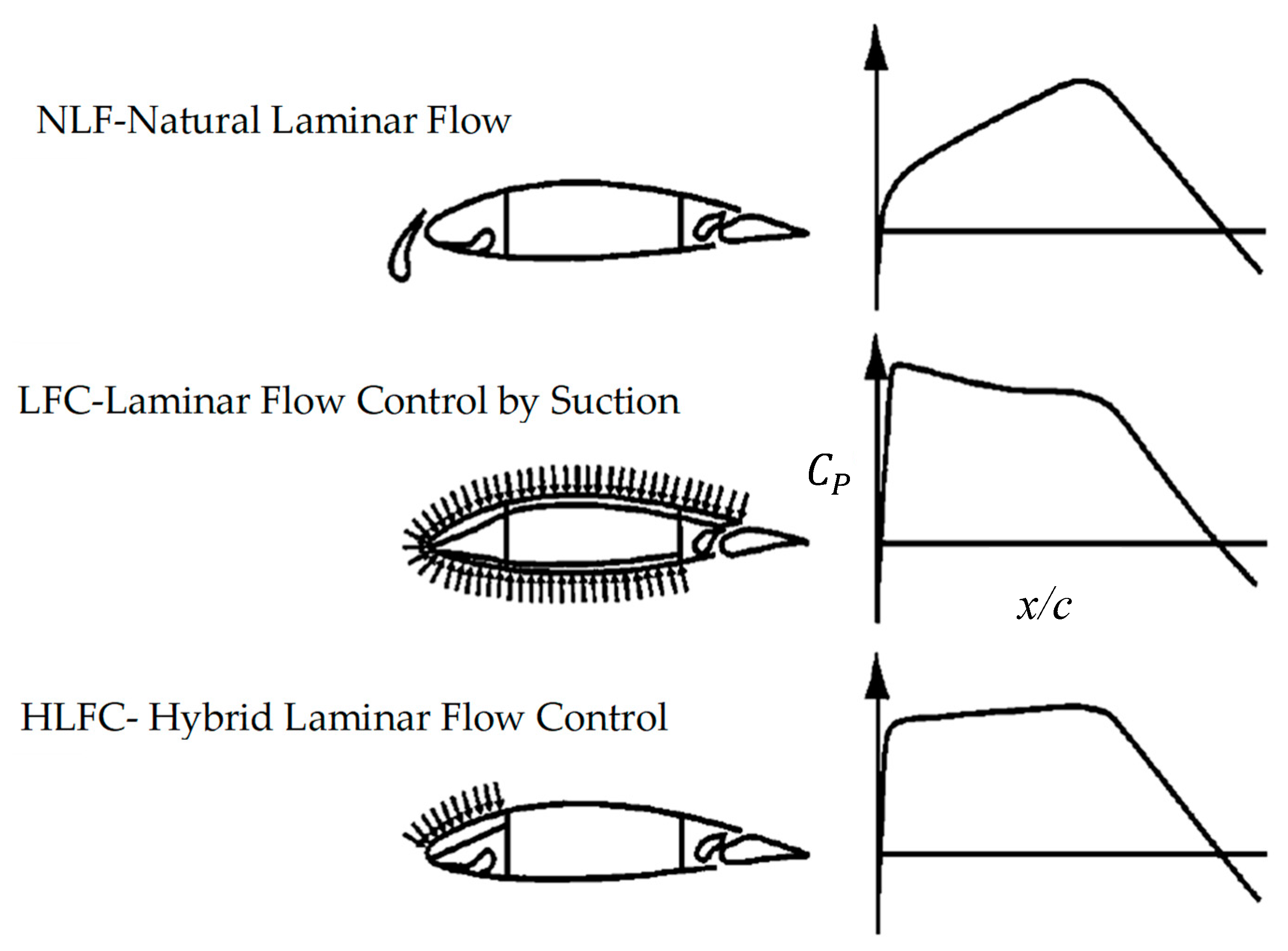
Figure 1. Schematic of natural laminar flow (NLF), laminar flow control (LFC) and hybrid laminar flow (HLFC) approaches for wing from [6].
Energies 11 00383 g001
Figure 2. Multi-bubble cross section of the inner shell with floor.
Energies 11 00383 g002
Figure 3. Structural components of the multi-bubble fuselage comprising of (a) generated 3D cabin skin, (b) separate outer skin, (c) cross ribbed design for the inner and outer skin, (d) interrupted walls, (e) floor connected to walls and cabin skin and (f) stringers in the curved cabin skin. Here, (g) represents the division of the fuselage in the chord wise direction.
Energies 11 00383 g003
Figure 4. Cross section of the fuselage with applied loads, reference points and constraints.
Energies 11 00383 g004
Figure 5. Controlled fiber placements for a rectangular based perforation arrangement in a [0/90]s composite laminate.
Energies 11 00383 g005
Figure 6. Controlled fiber placement (CFP) in the micro model: (a) fiber orientation defined by Equation (1) (b) variation in volume fraction within the micro-mechanical model.
Energies 11 00383 g006
Figure 7. Here (a) represents the 3D micro model comprising of [0/90]s laminate and (b) represents the front view of the 3D model, indicating the orientations as well as the matrix pocket, fish-eye and reinforced region.
Energies 11 00383 g007
Figure 8. Approximation of consequent strengths due to varying volume fractions in: (a) longitudinal and (b) transverse to fiber and shear directions.
Energies 11 00383 g008
Figure 9. Stress distributions and the deflections for the two different fuselage configurations. (a,c) correspond to configuration 1, (b,d) correspond to configuration 2.
Energies 11 00383 g009
Figure 10. Damaged elements for matrix failure criteria under compression in configuration 1.
Energies 11 00383 g010
Figure 11. Four bucking modes of the linear buckling analysis for configuration 1 with five span-ribs, five frames.
Energies 11 00383 g011
Figure 12. Four bucking modes of the linear buckling analysis for configuration 2 with 10 span-ribs, 10 frames.
Energies 11 00383 g012
Figure 13. Strain distribution in the outer skin.
Energies 11 00383 g013
Figure 14. Flowchart of the fatigue damage model (FDM) with discontinuous and continuous method of degradation [11].
Energies 11 00383 g014
Figure 15. Simplified load spectrum based on TWIST [10].
Energies 11 00383 g015
Figure 16. Characterization of fatigue loading and relationship between the parameters in Equation (6).
Energies 11 00383 g016
Figure 17. Approximated S-N-curves for the simplified TWIST load spectrum for the 90° plies in the micro model.
Energies 11 00383 g017
Figure 18. Strength degradation in transverse direction for all three micro models: (a,b) perforated with CFP, (c,d) perforated without CFP, (e,f) unperforated. Left column load sequence high to low, right column load sequence low to high.
Energies 11 00383 g018aEnergies 11 00383 g018b
Table 1. Summary of the parameters and best technologies according to [8] for the long range BWB-design under consideration in the present work.
Long Range Blended Wing Body (BWB) Aircraft
Passengers300–400
Maximum takeoff weight MTOW (t)132
Operating empty weight OWE (t)78
Outer wing area (m2)133
Outer wingspan (m)53.3
Energy conversionIntercooled recuperated gas turbine, synchronized electric motor
Energy storageSynthetic fuel
Table 2. Thickness approximation for the simplified laminate configuration.
TypeLaminate Configuration/Thickness [mm]Total Thickness [mm]
Global fuselage laminate[45/0/-45/90/45/90/-45/90]s/(0.125)2
Simplified micro model
Without perforation[0/90]s/(0.27/0.52)1.58
With perforation, no CFP[0/90]s/(0.29/0.61)1.81
With perforations, with CFP[0/90]s/(0.27/0.57)1.68
Table 3. Comparison between configurations 1 and 2.
Numerical ResultsConf. 1Conf. 2
Max. stress (MPa)16461049
Max. deflection (mm)421257
First four eigenvalues λ0.82, 0.87, 0.89, 0.931.26, 1.31, 1.33, 1.36
Weight (kg/m2)34.6338.68
Weight of damaged elements to segment weight
Matrix compression1.26%0.58%
Matrix tension0.28%0.03%
Fiber compression0.00%0.00%
Fiber tension0.00%0.00%
Table 4. Parameter study for the laminate thickness of the span-ribs.
Numerical Resultst = 2 mmt = 3 mmt = 4 mmt = 5 mm
Max. stress (MPa)1811164615421472
Max. deflection (mm)439421410403
Weight (kg/m2)33.9134.6335.3536.06
Weight of damaged elements to segment weight
Matrix compression1.50%1.26%1.05%0.97%
Matrix tension0.39%0.28%0.20%0.15%
Fiber compression0.00%0.00%0.00%0.00%
Fiber tension0.00%0.00%0.00%0.00%
Table 5. Parameter study for the laminate layups of the outer skin.
Numerical Results[45/0/-45/90/
45/90/-45/90]s
[45/90/-45/0/
45/0/-45/0]s
[45/-45/45/-45/
45/-45/45/-45]s
Max. stress (MPa)164616721663
Max. deflection (mm)421423422
Weight (kg/m2)34.6334.6334.63
Weight of damaged elements to segment weight
Matrix compression1.26%1.27%1.27%
Matrix tension0.28%0.29%0.28%
Fiber compression0.00%0.00%0.00%
Fiber tension0.00%0.00%0.00%
Table 6. Fatigue data for each load block for the simplified load spectrum based on TWIST [10].
Load BlockVVIVIIVIIIIXX
R 0 0.09 0.19 0.31 0.45 0.63
n 5.2 × 10 2 1.52 × 10 3 8 × 10 3 4.17 × 10 4 3.48 × 10 5 3.59 × 10 6