Stirling Engine Configuration Selection


Abstract
:1. Introduction
2. Kinematic and Thermodynamic Comparison
- Zero displacer thickness (no dead volume due to the displacer).
- No dead volume in connection pipes or any other part.
- All the assumptions made by thermodynamics, such as infinite heat transfer time, ideal gas properties, uniform instantaneous gas temperature and pressure, etc.
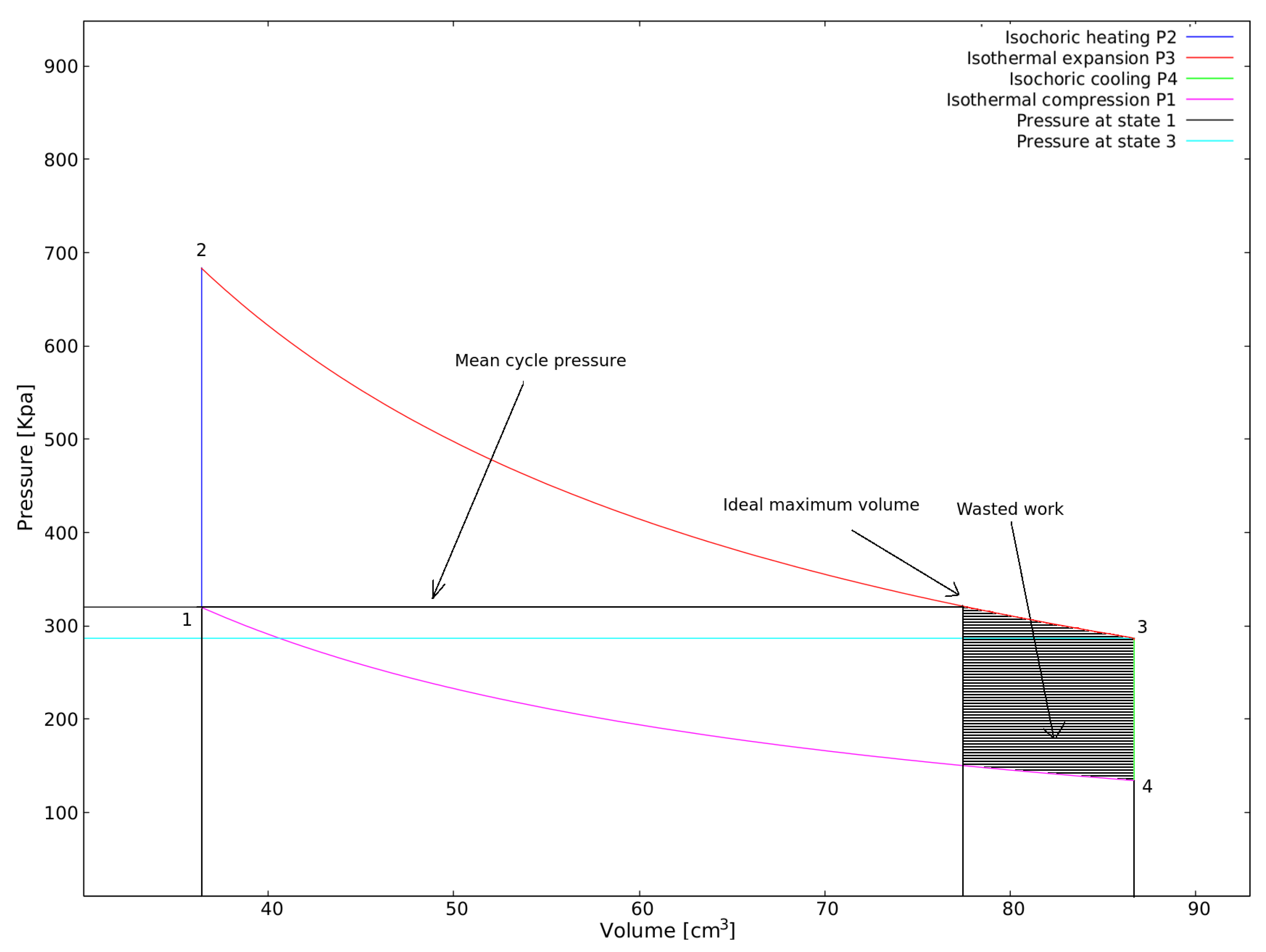
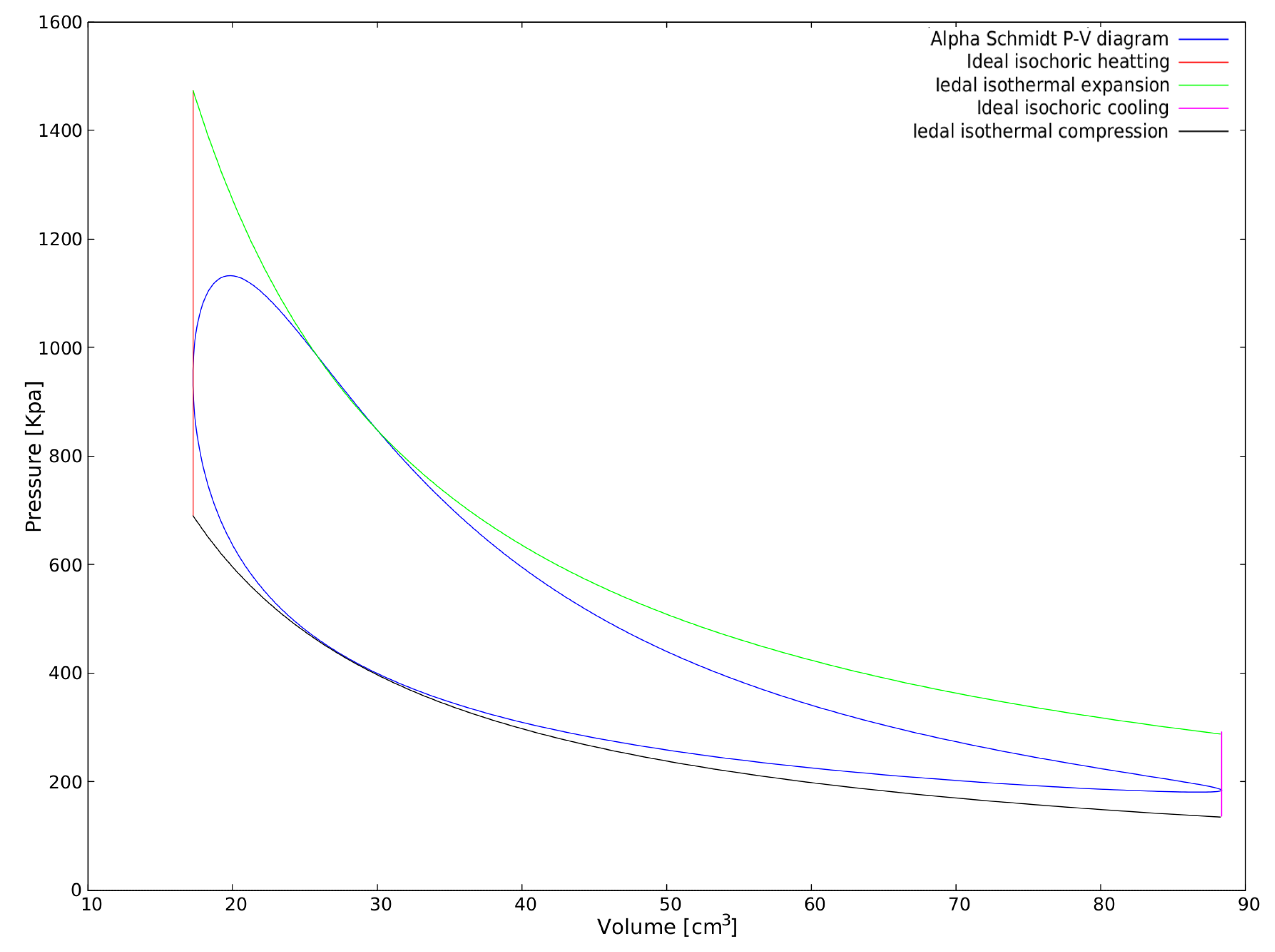
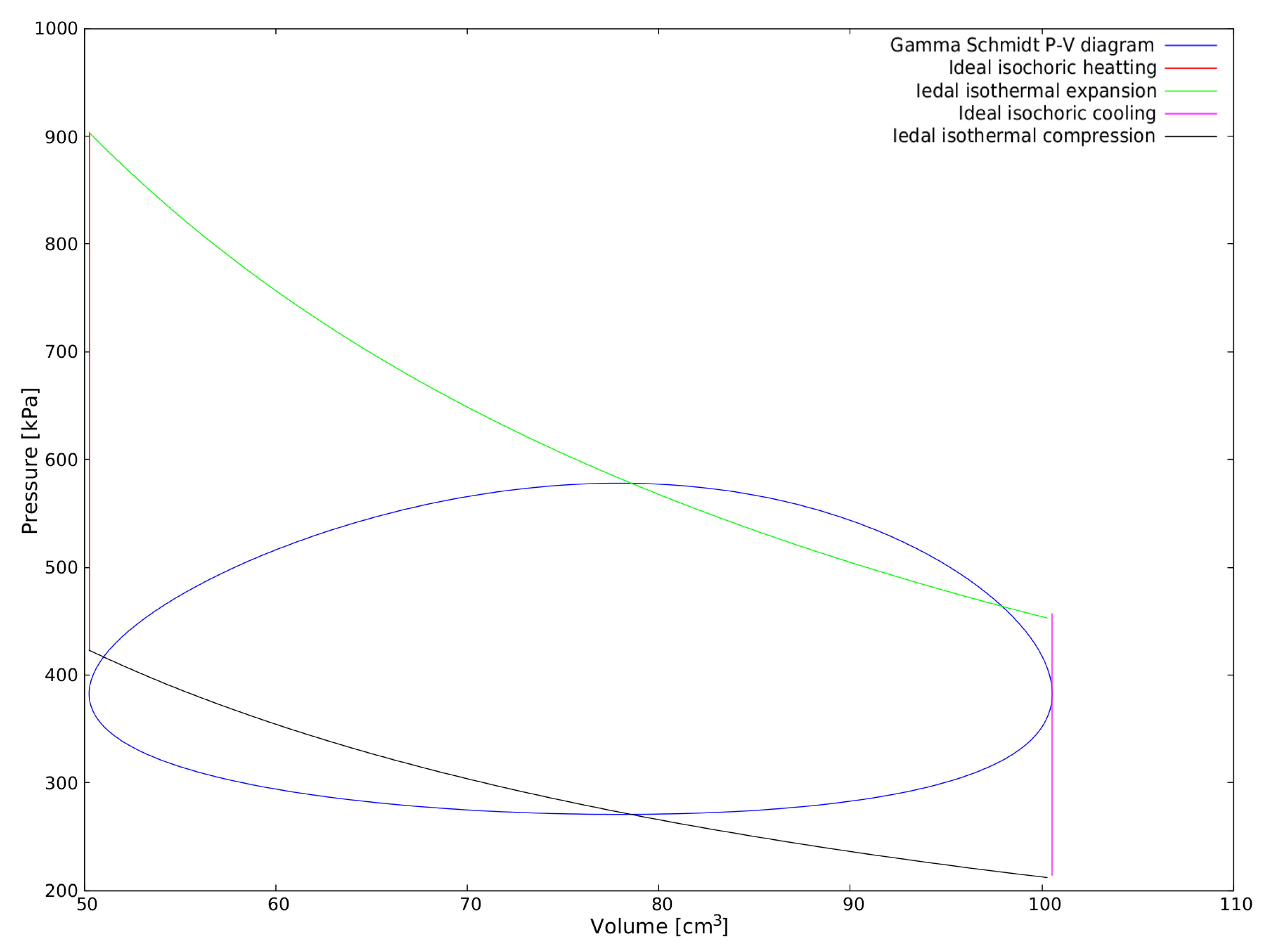
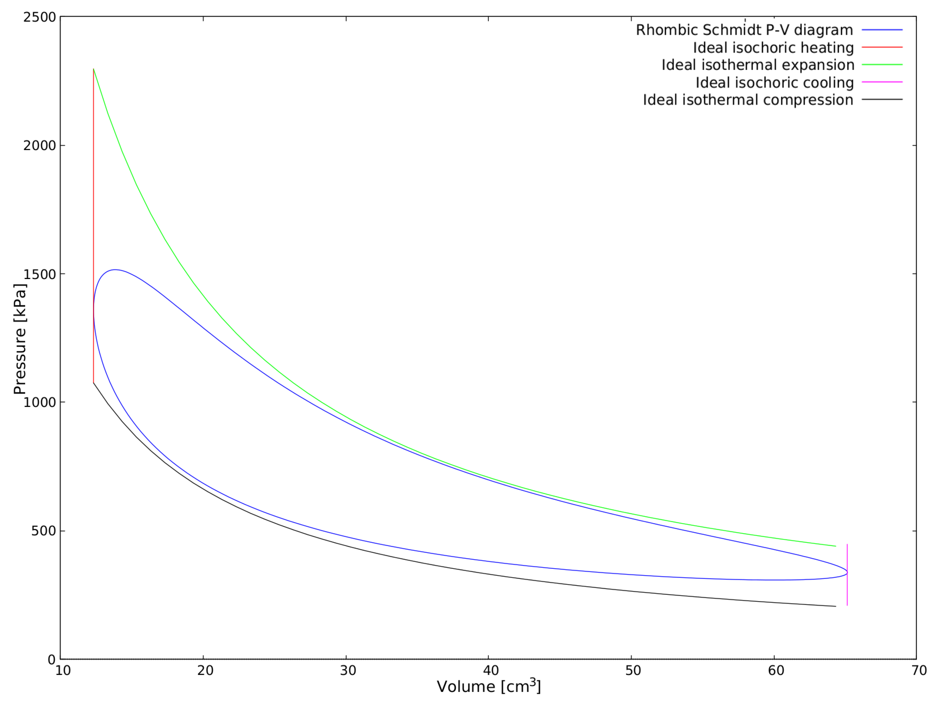
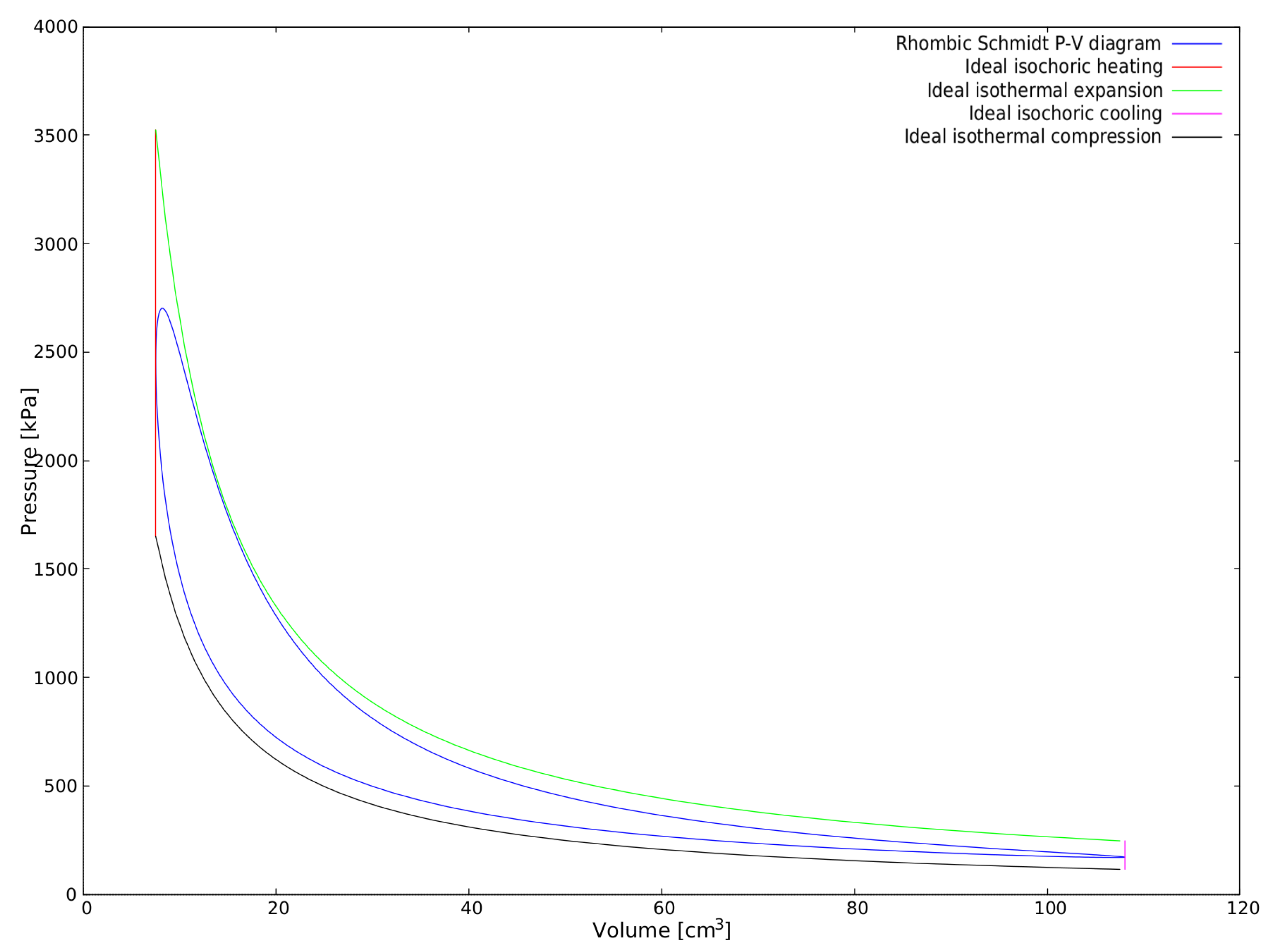
- p1: gas compression.
- p2: gas heating.
- p3: work process.
- p4: gas cooling.
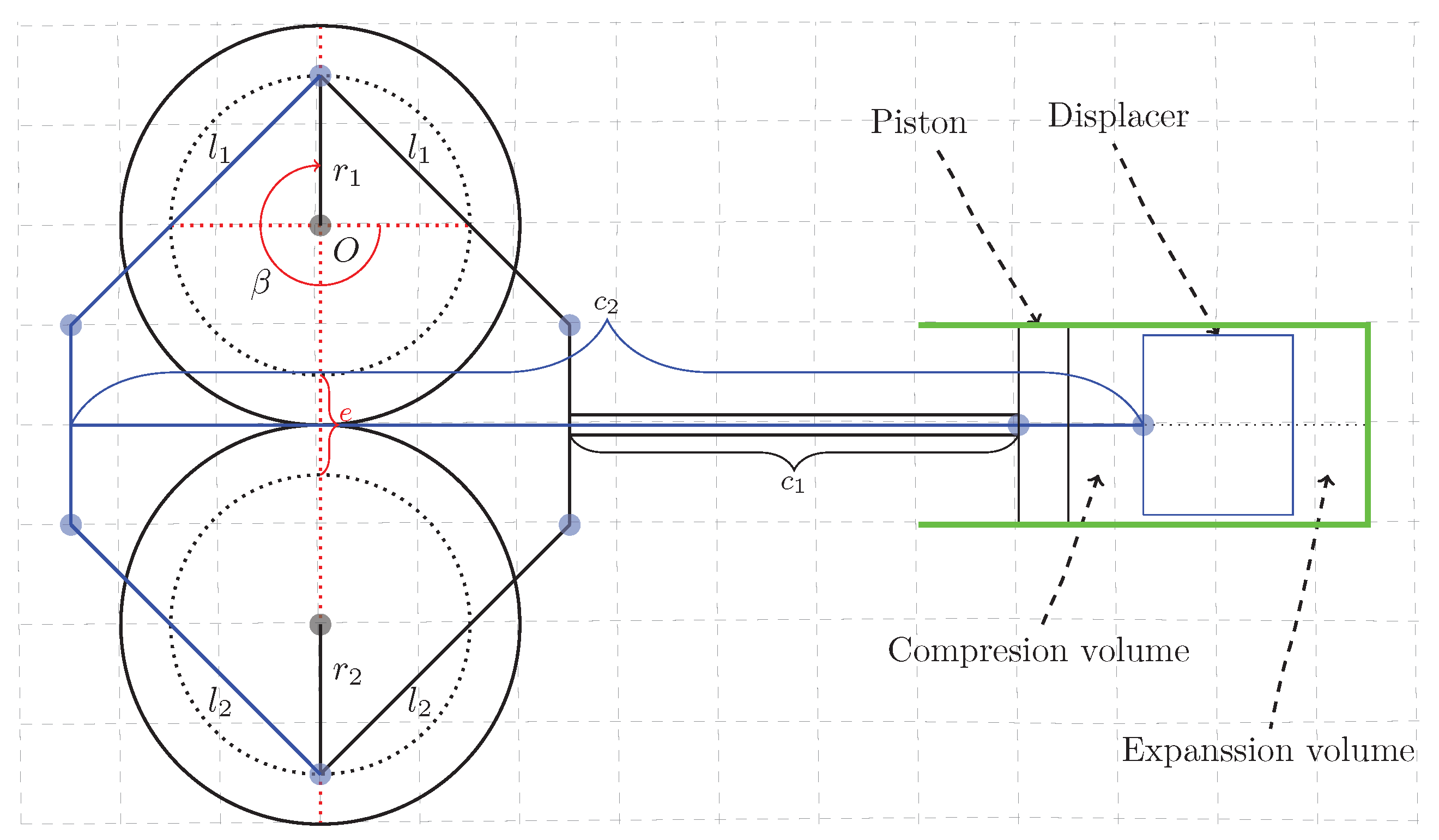
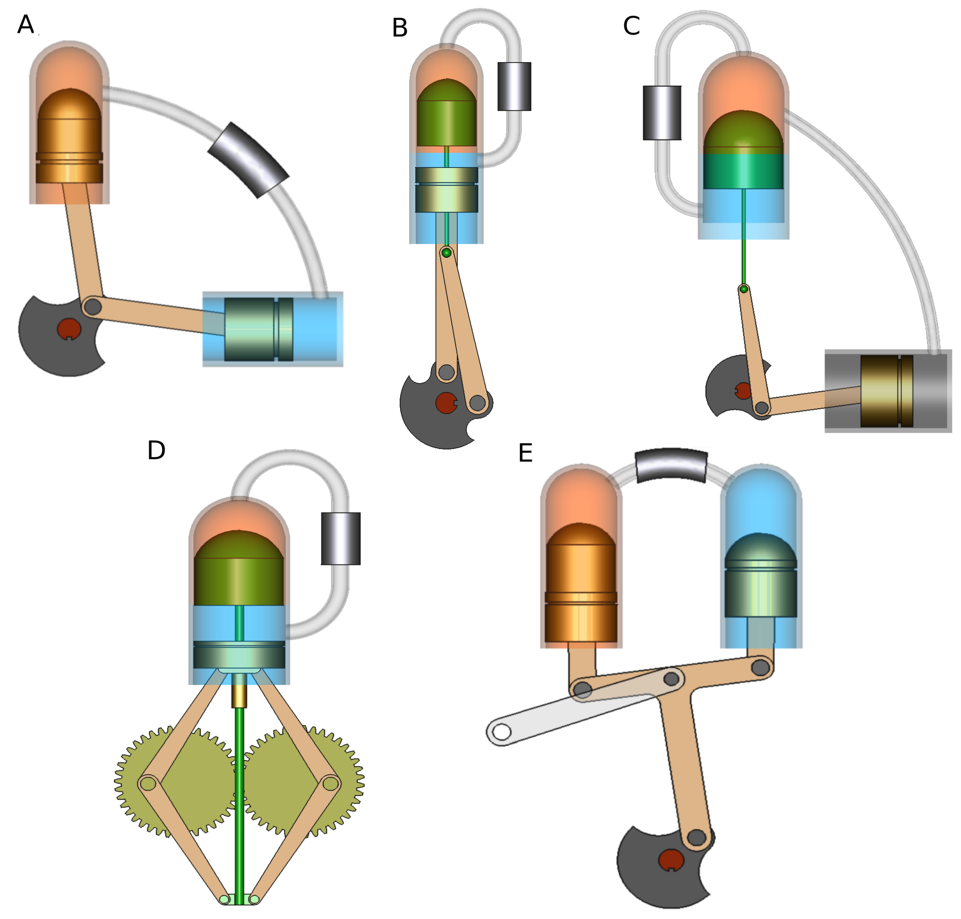
2.1. Beta with Crankshaft Drive
- O point represents the crank rotation center.
- segment represents the power piston crank radius ();
- segment represents the displacer crank radius ();
- segment represents the power piston connecting rod of length.
- segment represents the displacer connecting rod of length.
- segment represents power piston rod of length.
- segment represents displacer yoke rod of length.
- G point represents the displacer top dead center.
- angle represents the phase angle.
- angle represents the crank angle relative to the horizontal.
- are the crank radius for power piston and displacer respectively.
- are the connecting rod lengths for power piston and displacer respectively.
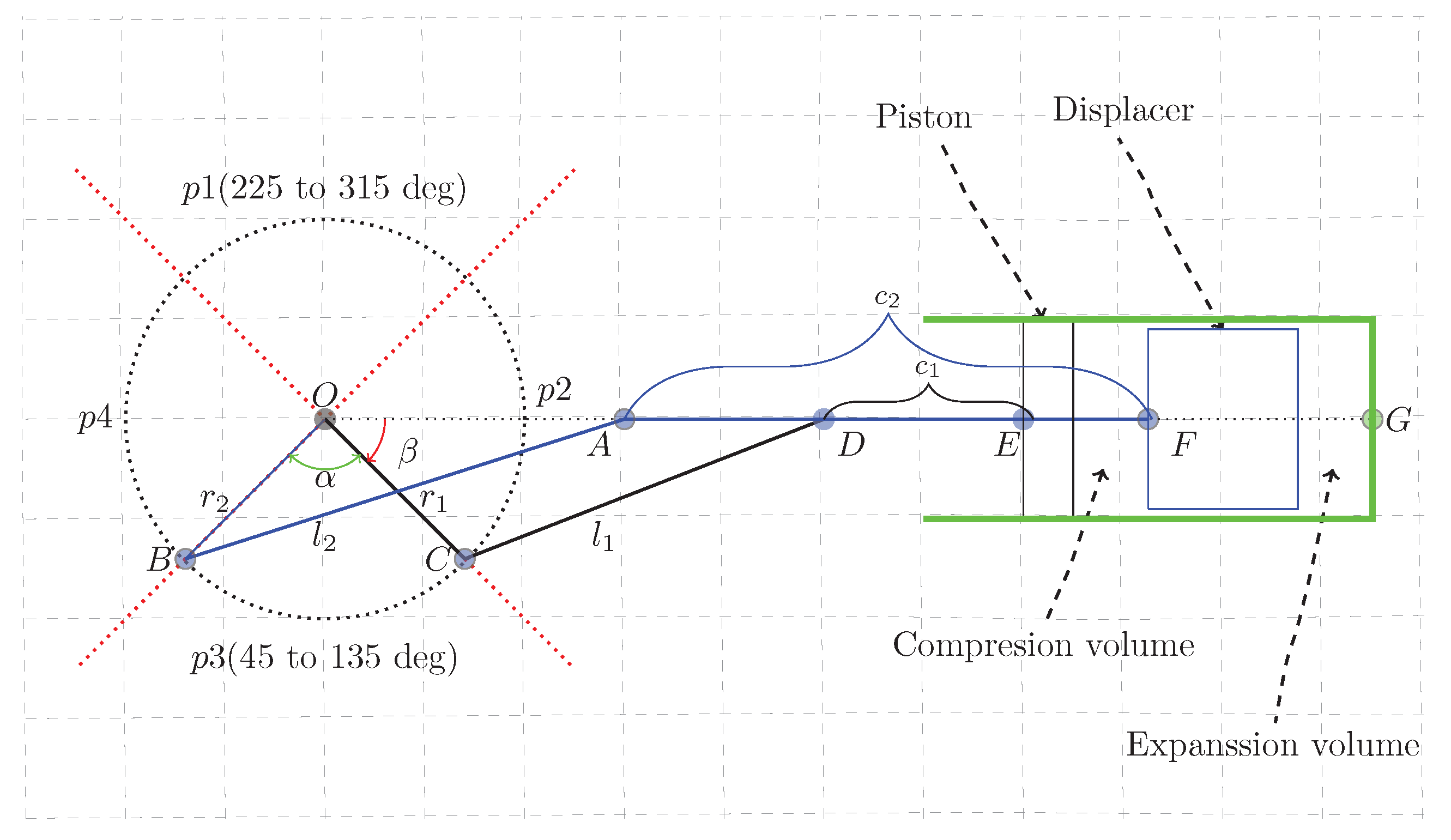
2.2. Alpha with Crankshaft Drive
- O point represents the crank rotation center.
- segment represents the crank of r radius.
- segment represents the expansion piston connecting rod of length.
- segment represents the compression piston connecting rod of length.
- E point represents the expansion piston top dead center.
- D point represents the compression piston top dead center.
- angle represents the phase angle.
- angle represents the crank angle.
- r is the crank radius.
- are the connecting rods lengths.
2.3. Gamma with Crankshaft Drive
2.4. Beta with Rhombic Drive and Alpha With Ross Yoke Mechanism
3. Kinematic Engines Proposed
- cm
- cm
- deg
- cm
- cm
- cm
- Equation (1) was introduced for the beta configuration to ensure there is one crank angle for which the clearance volume (volume contained between the displacer and the hot heat exchanger) is zero, thus, ensuring there is no dead volume. Then, the displacer kinematic equation (Equation (3)) was derived under this consideration. For our beta engine, this design consideration can be mathematically expressed as:Therefore, at least one crank angle () that determines zero expansion volume () must exist:Then, to ensure the minimum compression volume () during the work process, the same logic must be applied to the distance, that is, the distance between the power piston and the displacer (distance that determines the compression volume):If satisfied, conditions (33) and (34) ensure that: (i) there is no dead volume caused by inadequate scarce swept volume, (ii) that the expansion volume is as big as possible and the compression volume is as small as possible during the work process (p3), and (iii) that the compression volume is as big as possible and the expansion volume is as small as possible during the compression process (p1). To satisfy these two conditions we must adjust the connecting rods lengths. Under this criteria, the next lengths have been selected for our hypothetical engines:
- (a)
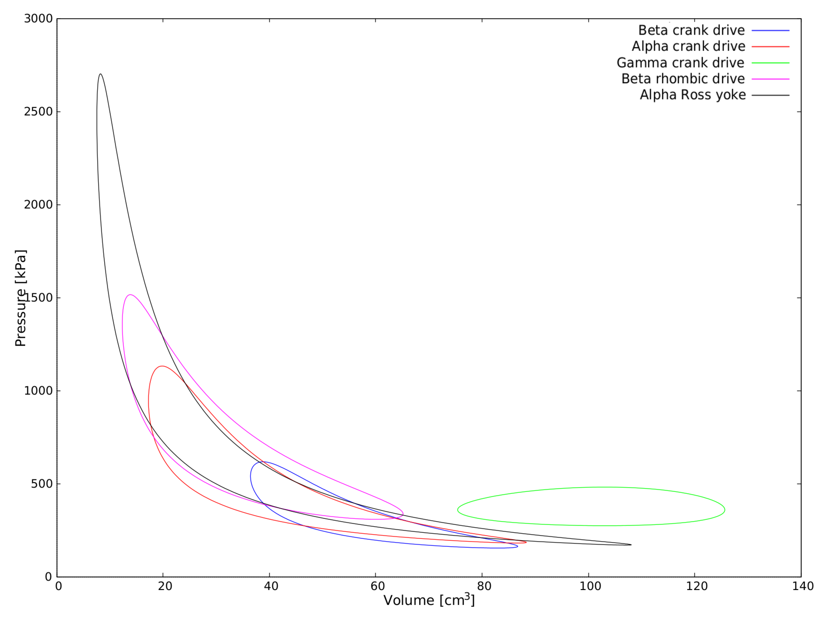
- Beta with crankshaft drive:
- cm
- cm
- cm
- cm
- (b)
- Alpha with crankshaft drive:
- cm
- (c)
- Gamma with crankshaft drive:
- cm
- cm
- (c)
- Beta with rhombic drive:
- cm
- cm
- cm
- (c)
- Alpha with Ross yoke:
- cm
- Zero dead volume is assumed within the five machines proposed.
- Perfect regeneration is assumed for the five machines proposed.
- kPa
- K
- K (Cold volume temperature)
- K (Hot volume temperature)
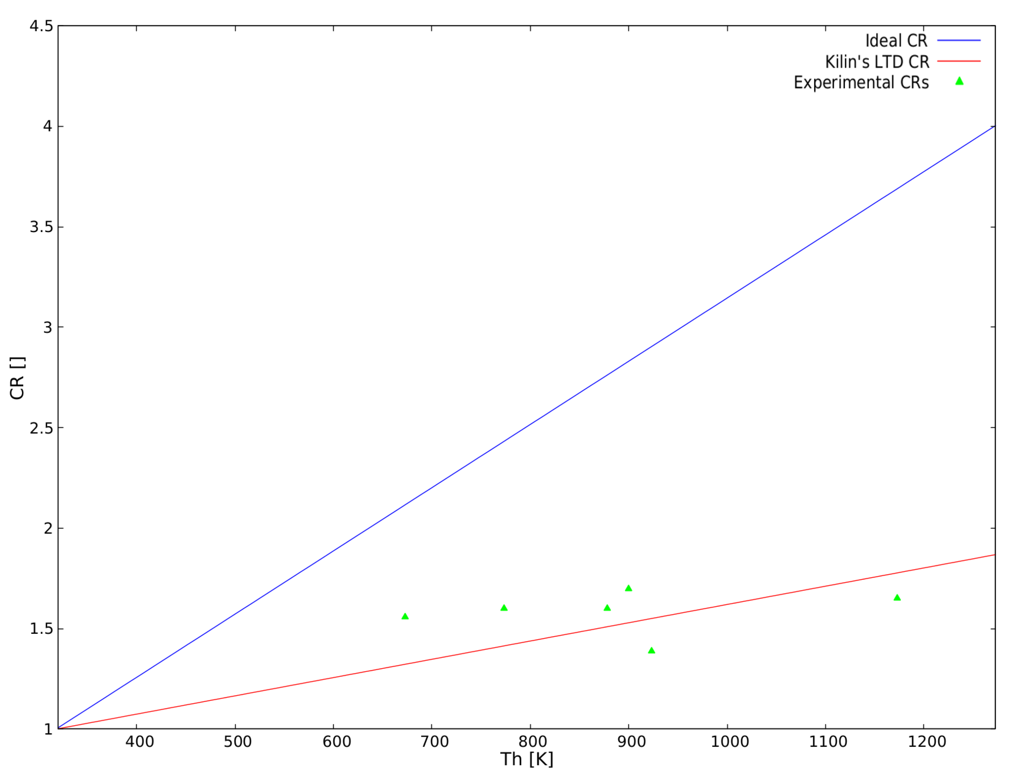
4. Compression Ratio as Function of Temperature Difference
5. Empirical Compression Ratio
6. Results
7. Discussion
- Alpha machines with Ross yoke are more suitable for high temperature difference applications, among which we may include high concentration ratio solar power (e.g., parabolic dish), nuclear power, high temperature geothermal energy, etc.
- Beta with rhombic drive and alpha with crank-slider machines are more suitable for medium-high temperature difference applications, which may include petrol or liquefied petroleum gas (LPG), medium concentration ratio solar (e.g., central tower or linear Fresnel lenses technologies), etc.
- Beta machines with crankshaft drive are more suitable for medium-low temperature difference applications; examples may include biofuels such as biogas or biodiesel, biomass combustion (agricultural or wood industry waste), etc.
- Only gamma machines are suitable for low and ultra low temperature difference applications, which may include low or zero concentration ratio solar power, low temperature geothermal energy, waste energy recovery, laboratory and educational applications, etc.
8. Conclusions
Author Contributions
Conflicts of Interest
References
- To, W.; Lee, P. Energy Consumption and Economic Development in Hong Kong, China. Energies 2017, 10, 1883. [Google Scholar] [CrossRef]
- Warner, K.; Jones, G. The Climate-Independent Need for Renewable Energy in the 21st Century. Energies 2017, 10, 1197. [Google Scholar] [CrossRef]
- Armeanu, D.; Georgeta, V.; Stefan, C. Does renewable energy drive sustainable economic growth? Multivariate panel data evidence for EU-28 countries. Energies 2017, 10, 381. [Google Scholar] [CrossRef]
- Kongtragool, B.; Wongwises, S. A review of solar-powered Stirling engines and low temperature differential Stirling engines. Renew. Sustain. Energy Rev. 2003, 7, 131–154. [Google Scholar] [CrossRef]
- Meybodi, M.A.; Behnia, M. Australian coal mine methane emissions mitigation potential using a stirling engine-based CHP system. Energy Policy 2013, 62, 10–18. [Google Scholar] [CrossRef]
- Mancini, T.; Heller, P.; Butler, B.; Osborn, B.; Schiel, W.; Goldberg, V.; Buck, R.; Diver, R.; Andraka, C.; Moreno, J. Dish-Stirling Systems: An Overview of Development and Status. J. Sol. Energy Eng. 2003, 125, 135–151. [Google Scholar] [CrossRef]
- Boutammachte, N.; Knorr, J. Field-test of a solar low delta-T Stirling engine. Solar Energy 2012, 86, 1849–1856. [Google Scholar] [CrossRef]
- Rey, G.; Ulloa, C.; Miguez, J.L.; Arce, E. Development of an ICE-based micro-CHP system based on a stirling engine; methodology for a comparative study of its performance and sensitivity analysis in recreational sailing boats in different European climates. Energies 2016, 9, 239. [Google Scholar] [CrossRef]
- Toro, C.; Lior, N. Analysis and comparison of solar-heat driven Stirling, Brayton and Rankine cycles for space power generation. Energy 2017, 120, 549–564. [Google Scholar] [CrossRef]
- Song, C.; Liu, Q.; Ji, N.; Deng, S.; Zhao, J.; Kitamura, Y. Advanced cryogenic CO2 capture process based on Stirling coolers by heat integration. Appl. Therm. Eng. 2017, 114, 887–895. [Google Scholar] [CrossRef]
- Araoz, J.A.; Salomon, M.; Alejo, L.; Fransson, T.H. Numerical simulation for the design analysis of kinematic Stirling engines. Appl. Energy 2015, 159, 633–650. [Google Scholar] [CrossRef]
- Wang, K.; Sanders, S.R.; Dubey, S.; Choo, F.H.; Duan, F. Stirling cycle engines for recovering low and moderate temperature heat: A review. Renew. Sustain. Energy Rev. 2016, 62, 89–108. [Google Scholar] [CrossRef]
- Gopal, V.K.; Duke, R.; Clucas, D. Active stirling engine. In Proceedings of the IEEE Region 10 Annual International Conference, Singapore, 23–26 January 2009; pp. 1–6. [Google Scholar]
- Tavakolpour-Saleh, A.R.; Zare, S.H.; Bahreman, H. A novel active free piston Stirling engine: Modeling, development, and experiment. Appl. Energy 2017, 199, 400–415. [Google Scholar] [CrossRef]
- Conroy, G.; Duffy, A.; Ayompe, L.M. Economic, energy and GHG emissions performance evaluation of a WhisperGen Mk IV Stirling engine u-CHP unit in a domestic dwelling. Energy Convers. Manag. 2014, 81, 465–474. [Google Scholar] [CrossRef]
- Walker, G.; Senft, J.R. Free-Piston Stirling Engines; Springer: Berlin/Heidelberg, Germany, 1985; pp. 23–99. [Google Scholar]
- Fedele, L.; Nasco, V.W.G. Research and development of a biomass fired Ringbom-Stirling engine. In Proceedings of the Eight International Stirling Engine Conference and Exhibition, Ancona, Italy, 27–30 May 1997. [Google Scholar]
- Podesser, E. Small scale cogeneration in biomass furnaces with a Stirling engine. In Proceedings of the Eight International Stirling Engine Conference and Exhibition, Ancona, Italy, 27–30 May 1997. [Google Scholar]
- Liu, B.; Li, L. Design of a domestic free piston Stirling electric power system. In Proceedings of the Eight International Stirling Engine Conference and Exhibition, Ancona, Italy, 27–30 May 1997. [Google Scholar]
- Carlsen, H. Field test of 40kW Stirling engine for wood chips. In Proceedings of the Eight International Stirling Engine Conference and Exhibition, Ancona, Italy, 27–30 May 1997. [Google Scholar]
- Pålsson, M.; Carlsen, H. Development of a wood powder fuelled 35 kW Stirling CHP unit. In Proceedings of the 11th ISEC (International Stirling Engine Conference), Rome, Italy, 19–21 November 2003; pp. 221–230. [Google Scholar]
- Damirchi, H.; Najafi, G.; Alizadehnia, S.; Mamat, R.; Nor Azwadi, C.S.; Azmi, W.H.; Noor, M.M. Micro Combined Heat and Power to provide heat and electrical power using biomass and Gamma-type Stirling engine. Appl. Therm. Eng. 2016, 103, 1460–1469. [Google Scholar] [CrossRef]
- Beck Peter, C.K. Decentralized generation of energy out of biomass using enhanced technologies. In Proceedings of the 11th International Stirling Engine Conference, Rome, Italy, 19–21 November 2003. [Google Scholar]
- Arashnia, I.; Najafi, G.; Ghobadian, B.; Yusaf, T.; Mamat, R.; Kettner, M. Development of Micro-scale Biomass-fuelled CHP System Using Stirling Engine. Energy Procedia 2015, 75, 1108–1113. [Google Scholar] [CrossRef]
- Ahmadi, M.H.; Ahmadi, M.A.; Pourfayaz, F. Thermal models for analysis of performance of Stirling engine: A review. Renew. Sustain. Energy Rev. 2017, 68, 168–184. [Google Scholar] [CrossRef]
- Kolin, I. Stirling Motor: History-Theory-Practice; Inter University Center: Dubrovnik, Croatia, 1991. [Google Scholar]
- Cipri, K.; Lucentini, M.; Kolin, I. Stroke Volume Depending Upon Working Temperature. In Proceedings of the 11th International Stirling Engine Conference, Rome, Italy, 19–21 November 2003; University of Zagreb: Zagreb, Croatia, 2003; Volume D. [Google Scholar]
- Cinar, C.; Yucesu, S.; Topgul, T.; Okur, M. Beta-type Stirling engine operating at atmospheric pressure. Appl. Energy 2005, 81, 351–357. [Google Scholar] [CrossRef]
- Stouffs, P. Design of a 1kWe Stirling engine for solar CHP. In Proceedings of the European Stirling Forum 2000, Osnabrück, Germany, 22–24 February 2000. [Google Scholar]
- Huang, S. Developing and Improving a Small Stirling Engine for Educational Purposes. In Proceedings of the 13th International Stirling Engine Conference, Tokyo, Japan, 24–26 September 2007. [Google Scholar]
- Viebach, S. Simulation and Development of a Stirling Eengine for a small Cogeneration Unit. In Proceedings of the Eight International Stirling Engine Conference and Exhibition, Ancona, Italy, 27–30 May 1997. [Google Scholar]
- Jiri, M. New Cconstruction of the Stirling Engine. In Proceedings of the 11th International Stirling Engine Conference, Rome, Italy, 19–21 November 2003. [Google Scholar]
- Clucas, D.; Egas, J. Additive Manufactured Functional Prime Mover. Energy Procedia 2017, 110, 136–142. [Google Scholar] [CrossRef]


| Project Title | Ref. | Focus | Engine Configuration |
|---|---|---|---|
| Research and development of a biomass fired Ringbom-Stirling engine | [17] | Low technology users in developing countries | Hybrid (free displacer) |
| Small scale cogeneration in biomass furnaces with a Stirling engine | [18] | District heat plants working with biomass | Alpha type adapted from a motorcycle engine |
| Design of a domestic free piston Stirling-electric power system | [19] | Remote regions in developing countries | Free piston |
| Field test of 40 kW Stirling engine for wood chips | [20] | Decentralized CHP and CO reduction | Alpha double acting four cylinder |
| Development of a wood powder fueled 35 kW Stirling CHP unit | [21] | Blocks of flats, schools, local heat production plats, woody industry. | Double acting four cylinders alpha |
| Micro Combined Heat and Power to provide heat and electrical power using biomass and Gamma-type Stirling engine | [22] | Micro co generation | Gamma type |
| Descentralized generation of energy out of biomass using enhaced technologies | [23] | Waste wood energy recovery | SOLO161 with adapted heat exchanger. |
| Development of micro-scale biomass-fuelled CHP system using Stirling Engine | [24] | Biomass—wood powder | Gamma type. |
| Engine | Experimental | ||||
|---|---|---|---|---|---|
| 5 W beta with crank drive [28]. | 1173 | 303 | 3.9 | 1.8 | 1.65 |
| 1 kW beta with rohombic drive [29]. | 900 | 330 | 2.7 | 1.5 | 1.7 |
| 15 W crank based beta [30]. | 773 | 293 | 2.64 | 1.44 | 1.6 |
| 417 W crank based beta [31]. | 923 | 343 | 2.69 | 1.53 | 1.39 |
| 0.9 kW beta with innovative drive [32]. | 673 | 323 | 2.10 | 1.31 | 1.65 |
| 1 kW solar powered alpha [27]. | 878 | 318 | 2.75 | 1.50 | 1.60 |
| Beta with crank drive | 2.33 | 2.14 | 1.41 |
| Alpha with crank drive | 5.12 | 2.14 | 1.41 |
| Gamma with crank drive | 2.00 | 2.14 | 1.41 |
| Beta with rhombic drive | 5.28 | 2.14 | 1.41 |
| Alpha with Ross yoke | 14.33 | 2.14 | 1.41 |
© 2018 by the authors. Licensee MDPI, Basel, Switzerland. This article is an open access article distributed under the terms and conditions of the Creative Commons Attribution (CC BY) license (http://creativecommons.org/licenses/by/4.0/).
Share and Cite
Egas, J.; Clucas, D.M. Stirling Engine Configuration Selection. Energies 2018, 11, 584. https://doi.org/10.3390/en11030584
Egas J, Clucas DM. Stirling Engine Configuration Selection. Energies. 2018; 11(3):584. https://doi.org/10.3390/en11030584
Chicago/Turabian StyleEgas, Jose, and Don M. Clucas. 2018. "Stirling Engine Configuration Selection" Energies 11, no. 3: 584. https://doi.org/10.3390/en11030584
APA StyleEgas, J., & Clucas, D. M. (2018). Stirling Engine Configuration Selection. Energies, 11(3), 584. https://doi.org/10.3390/en11030584