Article

A Reliability Assessment Method for High Speed Train Electromagnetic Relays

School of Electrical Engineering, Beijing Jiaotong University, Beijing 100044, China
*
Author to whom correspondence should be addressed.
Energies 2018, 11(3), 652; https://doi.org/10.3390/en11030652
Submission received: 18 January 2018 / Revised: 7 March 2018 / Accepted: 12 March 2018 / Published: 14 March 2018

Abstract

:
The condition of electromagnetic relays is crucial to the safe and normal operation of the high-speed train (HST). At present, there are no proper testing and assessment methods for the condition of electromagnetic relays. Electromagnetic relays experience aging and failure over their service time, which causes many potential security problems. To solve these problems, the failure mechanisms of electromagnetic relays are analyzed. The Fick diffusion theory and the Larson–Miller method are used to deduce the degradation models for contact resistance and closing time. Based on these models, an approach to calculate relay life is proposed. To verify the effectiveness of the proposed method, a test platform was designed and built. The accelerated life test was carried out by using Siemens 3TH electromagnetic relays (3TH4244-OLF4, Siemens, Suzhou, China). Contact resistance and closing time were measured using a test platform. The least squares fitting was used to calculate the residual sum of squares and the unknown parameters in the degradation models with the test data. The optimal degradation model was chosen according to the fitting results. Relay life at four temperature stress levels was predicted by the optimal degradation model and failure threshold of the relays. The result indicates that the life of the electromagnetic relays at ambient temperature is 11,874 days and prediction error is about 5%, which provides important guidance for the maintenance of electromagnetic relays.

Graphical Abstract

1. Introduction

The electromagnetic relay is an automatic switch with isolated function, which is widely used in the high-speed train (HST). With the development of the HST, its safety and normal operation have become very important. The electromagnetic relay is a crucial control element in electronic devices. Relay failure endangers the safety of the HST, and even leads to accidents. Therefore, it is of great significance to study the reliability assessment method for relays.
The reliability assessment method for relays includes the failure mechanism analysis, the establishment and selection of the degradation model, and the accelerated life test. The purpose of the failure mechanism analysis is to determine the characteristic parameters of the relay. The purpose of the degradation model is to describe the changes of the characteristic parameters over time. The accelerated life test is carried out to verify the effectiveness of the reliability assessment method.
Traditional failure mechanism analysis is based on observing the contact surface with the naked eye, or using devices such as the optical microscope [1,2]. Using this method, the intuitive failure information is obtained, but shucking the sealed relays is time-consuming, laborious, and sometimes they are even inoperable. To address these problems, some scholars have made investigations into the physical and chemical characteristics of the corrosion film between the contacts. The corrosion film is caused by the diffusion of the contact region [3,4]. Most of these investigations have focused on the failure mechanism of the contacts. However, the time parameter is also important [5]. Therefore, this paper analyzes the failure mechanism of the relay from two aspects: contact resistance and closing time.
There has been much research on reliability assessment methods for aerospace relays in a storage condition [6,7]. However, the research on relays in a storage condition is not in accordance with the actual condition in the HST. The research on relays in a work condition is limited. In addition, the degradation model is also proposed in the storage condition [8,9]. The analysis of the degradation model is an independent incremental process using the linear mean [10,11]. However, because of the impact of the contact material, structural parameters, environmental factors, and the complexity of the failure mechanism, there is substantial difficulty in establishing a precise mathematical model. Therefore, this paper deduces the degradation model for contact resistance and closing time. The optimal degradation model is chosen by the residual sum of squares.
Since no or very few failures occur during the normal test, the relays are highly reliable over a long time period. It is difficult to assess reliability using traditional life test methods in a short time period [12,13]. For this reason, a low-cost test method that can be used in a short time period needs to be studied. In recent years, the new method of the accelerated life test based on the degradation parameter has been used widely. This test method has the advantage of shortening the test time, and obtains more information than the traditional accelerated life test [14,15]. To date, the method has been used in the areas of aerospace electronics, rolling bearings, and lithium batteries [16,17,18]. However, there is only limited research on relays used in the HST.
The sections of this paper are organized as follows: The failure mechanism is analyzed in Section 2. A reliability assessment method is proposed in Section 3. The contact resistance degradation model and the closing time degradation model are derived in Section 4. In Section 5, verification of the effectiveness of the proposed method is discussed, with a test platform designed and built to measure contact resistance and closing time using the accelerated life test method. In 
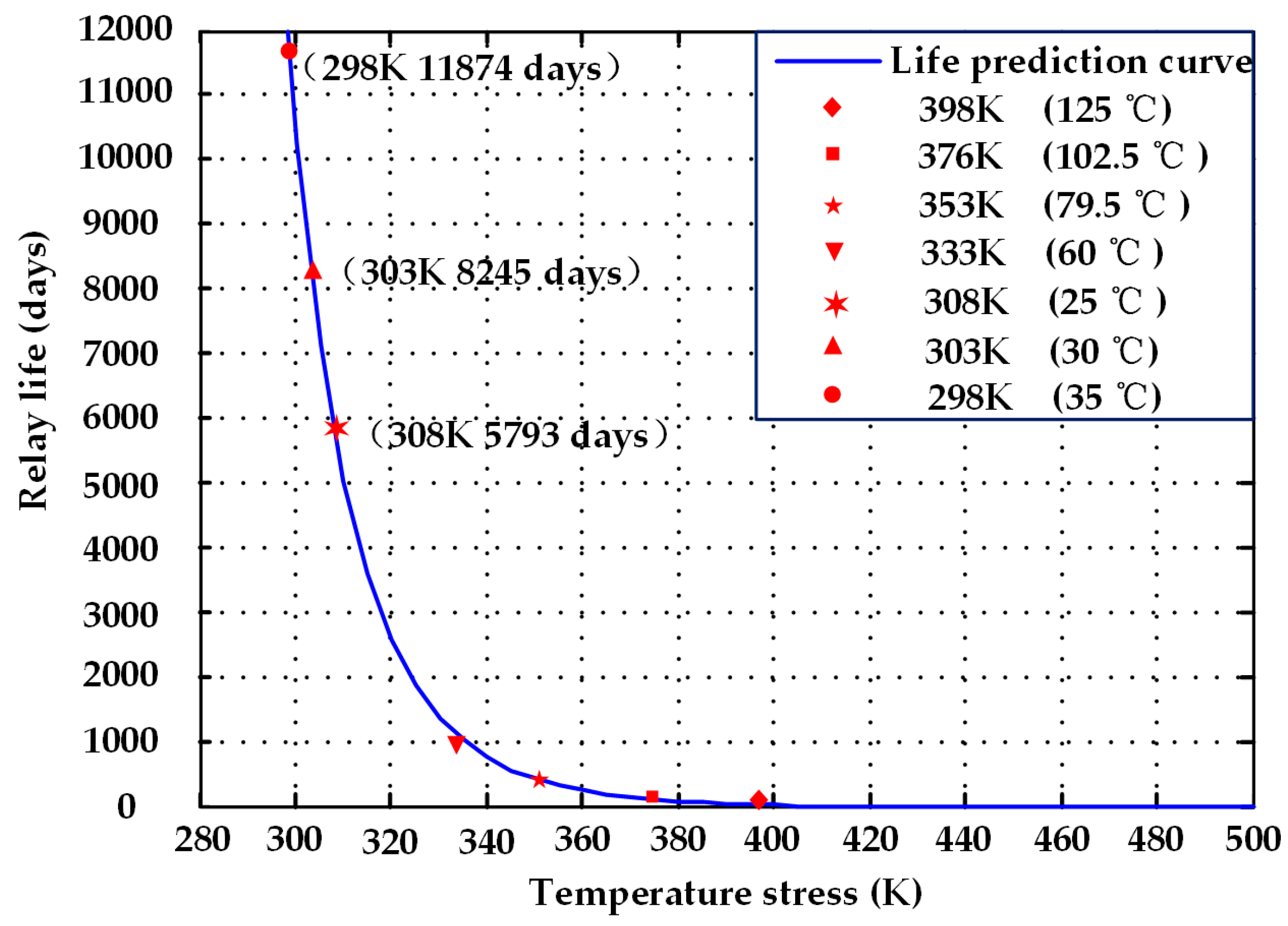
Section 6, the optimal degradation model is chosen according to the fitting results. Relay life at four temperature stress levels is predicted using the optimal degradation model and failure threshold. Finally, relay life at ambient temperature is calculated, according to the above life characteristics and the Arrhenius model.

2. Failure Mechanism

2.1. Common Failure Mechanisms

Failure mechanism analysis is an important part of the reliability assessment. Electromagnetic relays work in a variety of environments, differing in factors such as temperature, humidity, and vibration. Temperature influences the parameter variation of relays, and leads to increasing contact resistance. Moisture accelerates the oxidation of surface material, and leads to corrosion of the contacts. In addition, mechanical vibration can cause the device to loosen. Taking into account these various factors, we cannot directly establish the degradation model. Therefore, the principle of the controlled variable method is used to carry out reliability research on the relays. The mechanism and manifestation of failures of electromagnetic relays are shown in Table 1 [19].

2.2. Failure Mechanism Analysis

The contact system is the core of an electromagnetic relay. The contact and spring are important components of the contact system shown in Figure 1. Contact failures of relays manifest mainly as changes in the electrical parameter and time parameter. Therefore, the failure mechanism of relays is analyzed from these two characteristic parameters.
The oxidative corrosion of the surface material is one of the critical factors that influences electrical reliability. When the relay is disconnected, an arc is generated and energy is lost. Because the relays work in complex environments, their contact surfaces develop a corrosive film. The corrosive film causes reduction of the electrical contact area and changes the contact resistance. When the whole contact surface is covered by the corrosive film, conductivity decreases, and may even cause a serious contact failure. The growth rate of the corrosion film is related to the ambient temperature of the contact surface [20]. High temperatures accelerate the growth rate of the corrosion film. The growth rate of the corrosion film directly affects the rate of change in contact resistance. Finally, the corrosion film leads to the increase of contact resistance. Thus, the change in contact resistance caused by the corrosion film is an important failure mechanism for the contact failures of electromagnetic relays.
In addition, the time parameter is also important. The electromagnetic relay works under the resultant force of the magnetic force and reaction force. According to Faraday’s law, the electric coil sets up the magnetic field. The magnetic field produces the force for the armature. The coil current is essentially constant, so the magnetic force remains unchanged [21]. It can be assumed that relay failure is not caused by the magnetic force. The reaction force is provided by the spring. It is necessary to overcome the reaction force of the spring in the relay’s closing process. As a spring element, the spring shows stress relaxation after long-term use. The spring stress relaxation is the conversion process of the material from taking elastic strain to plastic strain. As a result, the reaction force of the spring decreases, while the magnetic force is almost the same. The resulting combined force of the magnetic force and reaction force becomes larger, leading to a reduction in closing time. Therefore, the change in closing time as caused by the stress relaxation of the spring is another important failure mechanism of electromagnetic relays.

3. Degradation Model

The degradation model is used to describe the change in characteristic parameters over time. The selection of the optimal degradation model is key in this paper. This section deduces the degradation models for the contact resistance and closing time of relays. Some common models are taken as the alternatives for the optimal degradation model. The optimal degradation model is selected from the degradation models, which provides a theoretical basis for the reliability assessment of electromagnetic relays.

3.1. Degradation Model of Contact Resistance

According to failure mechanism analysis, the corrosion film causes the contact performance degradation of relays. According to the literature [22,23,24,25], the form of the corrosion film is mainly related to the diffusion of the contact surface. The microcontact model of the metal contact is established. The thickness of the corrosion film is negligible, so the three-dimensional Fick equation is converted into the two-dimensional radial diffusion equation.
The distance of the corrosion film that infiltrates into the contact surface is
Φ = 2 γ D f t
where γ is the erosion coefficient and t is the material diffusion time.
The diffusion coefficient of the corrosion zone is
D f = D 0 e Q a / ( R T m )
where D 0 is the frequency factor, Q a is the activation energy, R is the gas constant, and T m is the Kelvin temperature of the contact spot.
According to the Holm electrical contact theory:
T m 2 T 0 2 = U 2 4 L
where T 0 is the environment temperature, U is the contact voltage drop, and L is the Lorentz constant.
Substituting Equation (2) into Equation (1):
Φ = 2 γ D 0 e Q a / ( R T m ) t
According to the literature [26], the activation energy Q a can change into the effective activation energy Q a J α 3 . Therefore, the transformation of Equation (4) is:
Φ = 2 γ D 0 e ( Q a J α 3 ) / ( R T m ) t
where J is the contact stress and α is the atomic size of the surface.
According to the Holm electrical contact theory, the contact resistance at time t is
R t = ρ 1 , 2 1 n a i ( t ) = ρ 1 , 2 n A t
where ρ 1 , 2 denotes average conductivity, a i is the diameter of the conductive spot, n is the number of conductive spots, and A t is the average diameter of the conductive spot at time t .
The contact resistance at time zero is
R 0 = ρ 1 , 2 1 n a i ( t = 0 ) = ρ 1 , 2 n A 0
where A 0 is the average diameter of the conductive spot at time zero.
The relationship of A 0 and A t is
A t = A 0 2 Φ
Equation (5) is transformed into Equation (8):
A t = A 0 4 γ D 0 e ( Q a J α 3 ) / ( R T m ) t
Based on the above equations, the degradation model of contact resistance is
R t R 0 = A 0 A t = A 0 A 0 4 γ D 0 e ( Q a J α 3 ) / ( R T m ) t
where R t is the contact resistance at time t , R 0 is the contact resistance at time zero, A 0 is the average diameter of the conductive spot at time zero, and A t is the average diameter of the conductive spot at time t .
We define R 0 R t as Y and 4 γ A 0 1 D 0 1 2 as ψ. Equation (10) is transformed into Equation (11):
Y = 1 ψ e ( Q a J α 3 ) / 2 R T m t 1 2
where Y is the ratio of the contact resistance and ψ is the coefficient to be determined.
Combined with the data of the contact resistance in the Section 6, the least squares fitting was used to calculate the unknown parameters.

3.2. Degradation Model of Closing Time

The degradation model of closing time is derived by the Larson–Miller analysis method. Larson and Miller set up an empirical equation for the analysis of stress relaxation. The Larson–Miller parameter θ is
θ = T ( ln t + C ) × 10 3
where T is the Kelvin temperature, t is the test time, and C is a constant related to the steel material (C = 20).
The Larson–Miller analysis method is used to describe the stress relaxation of the spring. Δ F x is the remaining percentage of the reaction force:
Δ F x = F x F 0 = θ = T ( ln t + 20 ) × 10 3
where F x is the reaction force of the spring at time x and F 0 is the reaction force of the spring at time zero.
Based on this associated relationship, the ratio of the closing time is
Δ T x = T x T 0 = a F x F 0 + b
where Δ T x is the ratio of the closing time at time x and zero, T x is the closing time at time x , and T 0 is the closing time at time zero.
Equation (13) is substituted into Equation (14). The degradation model of the closing time is
Δ T x = T x T 0 = a T ( ln t + 20 ) + b
where a and b are the coefficients to be determined.
In combination with the data of closing time in Section 6, the least squares fitting was used to calculate the unknown parameters.

3.3. Common Model

The characteristic parameters change with time, according to Equations (10) and (15). Only the rate and trajectory of the degradation are different. The degradation model is the main factor affecting prediction accuracy. Thus, we must determine the form of the degradation model, and then calculate the unknown parameters. To compare the pros and cons of the degradation models, the common models are taken as the alternatives for the optimal degradation model.
(1)
Linear function:
G = a 1 + a 2 t
(2)
Parabolic function:
G = a 1 + a 2 t + a 3 t 2
(3)
Exponential function:
G = a 1 e a 2 t
(4)
Power function:
G = a 1 t a 2
(5)
Logarithmic function:
G = a 1 + a 2 ln t
In combination with the data in Section 6, the least squares fitting was used to calculate the unknown parameters and the residual sum of squares. The residual sum of squares was used to select the optimal degradation model from the proposed models. The smaller the residual sum of squares, the closer the fitting curve fits the actual data. Sixteen residual sums of squares were selected to reflect the approximation degree between the fitting curve and the actual data. The model with the smallest residual sum of squares was chosen as the optimal degradation model.

4. Reliability Life Test

4.1. Reliability Assessment Method

The contact and spring are essential components of the contact system. A reliability assessment method is proposed for adaptation to the relays used in the HST, as shown in Figure 2. Firstly, the Fick diffusion theory [27] and the Larson–Miller method [28] are used to deduce the degradation models of contact resistance and closing time. In addition, several common models are selected as candidates for the optimal degradation model. Closing time and contact resistance were measured on the test platform. The unknown parameters of the degradation models were calculated by the least squares fitting in MATLAB (R2010a, MathWorks, Natick, MA, USA). To compare the degradation models, 16 residual sums of squares were calculated. The optimal degradation model was chosen by having the smallest residual sum of squares. Combined with the failure threshold of the relays, relay life at four temperature stress levels was predicted by the optimal degradation model. Finally, relay life at ambient temperature was calculated according to the above life characteristics and the Arrhenius model.

4.2. Test Platform

To provide data supporting the selection of the optimal degradation model and assess the reliability of relays with the optimal degradation model, a test platform was designed and built. The accelerated life test was carried out using Siemens 3TH relays. Without changing the failure mechanism of the relays, the degradation rate of the relays was accelerated using a temperature chamber to make the relays degrade or even fail in a short time period, in order to obtain more life information. The test platform structure is shown in Figure 3.
The test platform includes an industrial computer (IPC-610L, Advantech, Beijing, China), resistance tester (TH2516, TongHui, Changzhou, China), adjustable power supply (APS24, DiPai, Hangzhou, China), oscilloscope (3000, Tektronix, Shanghai, China), high temperature chamber (GDWX-150-880-40, AODEMA, Shenzhen, China), hardware circuit (PCI8326A, ZTIC, Beijing, China), and LabVIEW Software (2012 SP1, National Instruments, Austin, TX, USA). The test platform is shown in Figure 4.

4.3. Stress Analysis

Temperature is the stressor in the accelerated life test. To accelerate the failure rate of the relays, it was necessary to determine the temperature stress levels. In order to satisfy the requirements of the data analysis, four temperature stress levels were chosen. Contact resistance and closing time were measured on the test platform. The Arrhenius model was selected as the acceleration model for the life test. Based on this model, the temperature was increased to obtain more life information. Thus, the minimum temperature stress was set to 60 °C. Taking into account the limit of the relay material (T ≤ 125 °C), the maximum temperature stress was set to 125 °C.
The middle temperature stresses were calculated using Equation (21):
Δ = 1 T 1 1 T 2 = = 1 T L 1 1 T L = 1 T 1 1 T L / ( L 1 )
where Δ is the temperature stress reciprocal interval, L is the number of stress level, T 1 is the minimum Kelvin temperature stress level, and T L is the maximum Kelvin temperature stress level.
The middle temperatures were 79.5 °C and 102.5 °C. Thus, the 16 relays were divided into four groups to carry out the accelerated life test at the four temperature stress levels. Contact resistance and closing time were measured every 24 h until the relay had cooled to the ambient temperature.

4.4. Methods for Test Systems

4.4.1. Test Method of Contact Resistance

The contact resistance test is shown in Figure 5. The relays P_K2 and C_K1 were to be closed. The adjustable DC was 110 V. When the MOS tube was conducted, the relay coil was energized. The relays C_K2 and C_K3 were to be closed. The contact resistance had been measured using the resistance tester. The operations were repeated 10 times to determine average contact resistance.

4.4.2. Closing Time Test Method

When conducting closing time tests, a set of open contacts was selected. The contacts connected the 5 Ω resistor to the 5 V DC source. The closing time test is shown in Figure 6.
The waveforms of the coil current and the contact voltage were measured using the oscilloscope. The CH1 connected to the differential voltage probe recorded the contact voltage. The oscilloscope was set to the falling edge of the single trigger. The trigger voltage was 4 V. When the relay was operating, the contact voltage dropped from 5 V to 0.3 V, as shown by the blue lines in Figure 7. The CH2 connected to the current probe recorded the coil current. The coil current began to grow exponentially, as shown by the green curve in Figure 7. The closing times were measured by adjusting the cursor on the oscilloscope. Finally, the operations were repeated 10 times to determine the average closing time.

5. Life Prediction of Electromagnetic Relay

5.1. Test Result of Characteristic Parameter

5.1.1. Test Result of Contact Resistance

We collected the values of contact resistance at four temperature stress levels (125 °C, 102.5 °C, 79.5 °C, and 60 °C). The values of contact resistance are shown in Figure 8.
The ratio R 0 / R t decreases over time, which means that the contact resistance increases. Thus, the increase in temperature will aggravate growth of the corrosion film, and lead to the increase of contact resistance.

5.1.2. Test Result of Closing Time

We collected the values of the closing time at four temperature stress levels (125 °C, 102.5 °C, 79.5 °C, and 60 °C). The values of the closing times are shown in Figure 9.
The relay closing time decreases gradually over time. Thus, the stress relaxation will influence the reaction force of the spring, and lead to the reduction of closing time.

5.2. Fitting Result

Closing time is approximately 40 ms and contact resistance is approximately 0.2 Ω. According to the Siemens technical manual for the relays, the failure thresholds for contact resistance and closing time are as follows:
(1)
The contact resistance is more than doubled, which is R t R 0 2 , when the relay has failed.
(2)
The closing time is less than 0.85, which is T x T 0 0.85 , when the relay has failed.
In order to compare the degradation models, the least squares fitting was used to calculate 16 residual sums of squares from the test data. The model with the smallest residual sum of squares was taken as the optimal degradation model for contact resistance. The residual sums of squares are shown in Table 2.
The smaller the 16 residual sums of squares, the better the degenerate model. According to Table 2, the model with the smallest residual sum of squares is the logarithmic function. Thus, the logarithmic function was chosen as the optimal degradation model. Combined with the failure threshold of contact resistance, life was predicted using the logarithmic function as shown in Table 3.
Similarly, the residual sums of squares are shown in Table 4. The model with the smallest residual sum of squares was taken as the optimal degradation model of closing time.
As shown in Table 4, the model with the smallest residual sum of squares is the closing time model. Therefore, the closing time model is chosen as the optimal degradation model. Combined with the failure threshold of closing time, the life of the electromagnetic relay is predicted using the closing time model as shown in Table 5.
When comparing physical models to mathematical models, the least squares fitting is used to calculate the residual sum of squares and unknown parameters from the test data. The optimal degradation model is chosen according to the smallest residual sum of squares. The smaller the residual sum of squares, the closer the fitting curve fits the actual data. Therefore, relay life was predicted using the mathematical model. Relay life at 125 °C was 46 days (1104 h), relay life at 102.5 °C was 124 days (2976 h), relay life at 79.5 °C was 286 days (6864 h), and relay life at 60 °C was 830 days (19,920 h).

5.3. Reliability Assessment

The reliability of electromagnetic relays is very high at ambient temperatures, so it is difficult to obtain enough data to predict relay life. In order to get more life information, the accelerated life test was carried out. The Arrhenius model is
ξ = A e E K T i
where ζ denotes life under T i stress, T i is temperature in Kelvin, E is the activation energy, K is the Boltzmann constant, and A is the coefficient.
Taking the logarithm on both sides of the equation a = ln A , b = E K :
ln ξ = a + b ( 1 T i )
The life prediction values of four temperature stress levels were substituted into Equation (23). The parameters a and b were calculated to obtain the relationship between the relay life and the temperature stress level:
ln ξ = 9.5427 + 6586.65 ( 1 T i )
Using Equation (24), the life prediction curve of the relays was obtained at each temperature stress level, as shown in Figure 10.
According to the Siemens technical manual, the mechanical life of Siemens 3TH electromagnetic relays is approximately 100 million cycles and the electrical life is approximately 10 million cycles. During the daily operation of the HST, the electromagnetic relays in the electrical cabinet usually operate at least eight times, from when the train leaves the station to after the process of running back. Combined with the electrical life of 10 million cycles, the relay life is approximately 12,500 days. As shown in Table 6, the life of the electromagnetic relays at ambient temperature is 11,874 days. The prediction error of the reliability assessment method is approximately 5%. Therefore, it is verified that the proposed reliability assessment method for electromagnetic relays is correct and effective.

6. Conclusions

In this paper, the failure mechanisms of electromagnetic relays were analyzed from two aspects: contact resistance and closing time. The method analyzed the characteristics of relay life. A reliability assessment method has been proposed. The contact resistance degradation model and the closing time degradation model were derived to establish the mathematical model of relay life. To verify the effectiveness of the proposed method, a test platform was designed and built to measure contact resistance and closing time, using the accelerated life test method. The least squares fitting was used to calculate the residual sum of squares and the unknown parameters in the degradation models from the test data. The optimal degradation model was chosen according to the fitting results. The relay life at four temperature stress levels was predicted using the optimal degradation model and failure threshold of the relays. Finally, relay life at ambient temperature was calculated, according to the above life characteristics and the Arrhenius model. The result indicates that the life of electromagnetic relays at ambient temperature is 11,874 days and that the prediction error is approximately 5%. The reliability assessment method provides important guidance for the maintenance of electromagnetic relays. In addition, the method can save maintenance time, reduce maintenance costs, and can be easily generalized to other types of HST.

Acknowledgments

This research was supported by the Chinese National Key Research and Development (R & D) Program 2017YFB1201304-09.

Author Contributions

Jianqiang Liu conceived and designed the experiments; Ming Zhang performed the experiments; Nan Zhao analyzed the data and contributed analysis tools; Ming Zhang wrote the paper; Aifeng Chen collected and analyzed the data with the experiments.

Conflicts of Interest

The authors declare no conflict of interest.

References

  1. Huang, J.; Strunk, H.P.; Wasserbäch, W. Internally oxidized silver contact materials—A case for the elastoplasticity of an inhomogeneous body. Cryst. Res. Technol. 2010, 44, 1147–1155. [Google Scholar] [CrossRef]
  2. Wu, C.P.; Yi, D.Q.; Xu, C.H. Microstructure of internally oxidized layer in Ag–Sn–Cu alloy. Corros. Sci. 2008, 50, 3508–3518. [Google Scholar] [CrossRef]
  3. Tamai, T. Effect of humidity on growth of oxide film on surface of copper contacts. IEICE Trans. Electron. 2007, 90, 1391–1397. [Google Scholar] [CrossRef]
  4. Read, M.B.; Lang, J.H.; Slocum, A.H. Contact resistance in flat thin films. In Proceedings of the 55th IEEE Holm Conference on Electrical Contacts, Vancouver, BC, Canada, 14–16 September 2009. [Google Scholar]
  5. Ye, X.; Yu, Q.; Zhai, G. Reliability assessment for electromagnetic relay based on time parameters degradation. In Proceedings of the International Conference on Electronic Packaging Technology & High Density Packaging, Xi’an, China, 16–19 August 2010; pp. 1269–1272. [Google Scholar]
  6. Lu, J.G.; Luo, Y.Y.; Li, W.H.; Meng, F.B.; Wang, L.Z. Storage Life Test and Failure Analysis of Aerospace Relays. Trans. China Electrotech. Soc. 2009, 24, 54–59. [Google Scholar]
  7. Wang, Z.; Zhai, G.; Ren, W.; Huang, X.; Yu, Q. Research on Accelerated Storage Degradation Testing for Aerospace Electromagnetic Relay. In Proceedings of the IEEE Holm Conference on Electrical Contacts, Portland, OR, USA, 23–26 September 2012; pp. 1–8. [Google Scholar]
  8. Kenmotsu, T.; Miyamoto, N.; Wada, M. Erosion of Extraction Electrodes of Ion Sources due to Sputtering. AIP Conf. Proc. 2011, 1321, 325–328. [Google Scholar] [CrossRef]
  9. Wang, Z.; Huang, Z.; Wang, J.; Shang, S.; Zhai, G. The failure mechanism of electromagnetic relay in accelerated storage degradation testing. In Proceedings of the IEEE Holm Conference on Electrical Contacts, Denver, CO, USA, 10–13 September 2017; pp. 164–168. [Google Scholar]
  10. Chen, Z.K.; Zheng, S. Lifetime distribution based degradation analysis. IEEE Trans. Reliab. 2005, 54, 3–10. [Google Scholar] [CrossRef]
  11. Wang, Z.H.; Fu, H.M.; Zhang, Y.B. Linear independent increment process with linear standard deviation function for degradation analysis. In Proceedings of the 10th International Conference on Applied Sciences & Technology, Islamabad, Pakistan, 15–19 January 2013. [Google Scholar]
  12. Ringsted, C.; Lippert, F.; Hesselfeldt, R. Assessment of advanced life support competence when combining different test methods—Reliability and validity. Resuscitation 2007, 75, 153–160. [Google Scholar] [CrossRef] [PubMed]
  13. Ma, H.; Meeker, W.Q. Optimum step-stress accelerated life test plans for log-location-scale distributions. Nav. Res. Logist. 2008, 55, 551–562. [Google Scholar] [CrossRef]
  14. Wang, S.; Yu, Q.; Ren, L.; Ren, W. Study on contact failure mechanisms of accelerated life test for relay reliability. IEICE Trans. Electron. 2009, 92, 1034–1039. [Google Scholar] [CrossRef]
  15. Chen, Z.K.; Witter, G.J. The effect of silver composition and additives on switching characteristics of silver tin oxide type contacts for automotive inductive loads. In Proceedings of the 51st IEEE Holm Conference on Electrical Contacts, Chicago, IL, USA, 26–28 September 2005; pp. 35–41. [Google Scholar]
  16. Behzad, M.; Arghan, H.A.; Bastami, A.R.; Zuo, M.J. Prognostics of rolling element bearings with the combination of paris law and reliability method. In Proceedings of the Prognostics and System Health Management Conference, Harbin, China, 9–12 July 2017; pp. 1–6. [Google Scholar]
  17. Xing, Y.; Williard, N.; Tsui, K.L.; Pecht, M. A comparative review of prognostics-based reliability methods for Lithium batteries. In Proceedings of the Prognostics and System Health Managment Confernece, Shenzhen, China, 24–25 May 2011; pp. 1–6. [Google Scholar]
  18. Hong, Y.F.; Liu, Z.Q.; Yin, H.X.; Zhang, J.H. A New Method for Smart Grid Reliability. In Proceedings of the Asia-Pacific Power and Energy Engineering Conference, Wuhan, China, 25–28 March 2011; pp. 1–4. [Google Scholar]
  19. Luo, Y.Y.; Lu, J.G.; Li, W.H. Study on the Accelerated Life Test of Storage Life for Sealed Electromagnetic Relays. Acta Armamentarll 2007, 28, 997–1001. [Google Scholar] [CrossRef]
  20. Chen, H.; Feng, F.; Qu, T.M. The Influence of Gas Flow Rate on the Growth of YBCO Films Prepared by TFA-MOD. IEEE Trans. Appl. Superconduct. 2009, 19, 3123–3126. [Google Scholar] [CrossRef]
  21. Wang, Z.B.; Fu, S.; Shang, S. New forecasting method of closing time for aerospace relay in storage accelerated degradation testing. In Proceedings of the 11th International Conference on Reliability, Maintainability and Safety (ICRMS), Hangzhou, China, 26–28 October 2016. [Google Scholar] [CrossRef]
  22. Malucci, R.D. Dynamic model of stationary contacts based on random variations of surface features. IEEE Trans. Compon. Hybrids Manuf. Technol. 1992, 15, 339–347. [Google Scholar] [CrossRef]
  23. Daniel, J.D.; Michael, T.D. Electrical Contact Resistance Degradation of a Hot-Switched Simulated Metal MEMS Contact. IEEE Trans. Compon. Packag. Technol. 2007, 30, 75–80. [Google Scholar] [CrossRef]
  24. Di, J.; Guo, S.; Cai, L. Enhanced corrosion resistance of sintered NdFeB magnets by diffusion of Co film prepared by direct current magnetron sputtering deposition. In Proceedings of the IEEE International Magnetics Conference, Beijing, China, 11–15 July 2015. [Google Scholar]
  25. Brian, G.M.; Eitan, A.; Marc, P.D.; Dennis, K. Failure mechanisms of legacy aircraft wiring and interconnects. IEEE Trans. Dielectr. Electr. Insul. 2008, 15, 184–185. [Google Scholar] [CrossRef]
  26. Galvele, J. A stress corrosion cracking mechanism based on surface mobility. Corros. Sci. 1987, 27, 1–33. [Google Scholar] [CrossRef]
  27. Mukherjee, M.; Chakravorti, S. Assessment of moisture diffusion distance in pressboard insulation within transformer using Fick’s law. In Proceedings of the 18th National Power Systems Conference, Guwahati, India, 18–20 December 2014. [Google Scholar]
  28. Wu, J.G.; Li, H.B.; Zheng, D.Q. Storage durability life and reliability analysis of welded metal bellows. In Proceedings of the 9th International Conference on Reliability, Maintainability and Safety, Guiyang, China, 12–15 June 2011. [Google Scholar]
Figure 1. The components of the relay.
Energies 11 00652 g001
Figure 2. The reliability assessment method.
Energies 11 00652 g002
Figure 3. Test platform structure.
Energies 11 00652 g003
Figure 4. Test platform.
Energies 11 00652 g004
Figure 5. Test method of contact resistance.
Energies 11 00652 g005
Figure 6. Test method of closing time.
Energies 11 00652 g006
Figure 7. The waveforms of coil current and contact voltage measured using the oscilloscope.
Energies 11 00652 g007
Figure 8. The test values of contact resistance.
Energies 11 00652 g008
Figure 9. The test values of closing time.
Energies 11 00652 g009
Figure 10. The life prediction curve of the relay at each temperature stress level.
Energies 11 00652 g010
Table 1. Mechanism and manifestation of failures of electromagnetic relays under single environmental stressors.
Stress TypeFailure MechanismFailure Manifestation
TemperatureOxidation, heat-agingContact resistance increase
MoistureAdsorption, infiltrationAccelerated corrosion
VibrationLoosening, abrasionMechanical damage
OtherAtmospheric corrosionContact resistance increase
Table 2. The residual sums of squares.
Relay NumberContact Resistance ModelLinear FunctionParabolic FunctionExponential FunctionPower FunctionLogarithmic Function
10.12280.11030.10980.11020.10810.1082
20.27430.13560.13560.13650.18100.1689
30.07190.08180.06830.07890.05750.0596
40.51810.38020.33730.36830.26570.2407
50.02600.04080.01630.03650.00650.0041
60.20510.23210.07830.37760.41180.2236
70.003880.000950.000770.001020.008530.008385
80.001560.001330.001330.001330.002540.00252
90.02450.03360.01760.03110.00440.0030
100.009140.005570.00490.0053320.022640.02187
110.00860.002120.0008490.0022930.014610.01443
120.01230.011330.011130.011330.010970.01097
130.01480.02490.00920.02280.00470.0033
140.07350.10520.07360.43680.25780.0496
150.267190.28110.35260.17390.25050.0721
160.18560.23690.55460.08960.25540.1069
SUM1.819271.68381.7721791.8835051.862691.098175
Table 3. Contact resistance degradation model and life prediction for different temperature stresses.
TemperatureDegradation ModelFailure ThresholdLife Prediction
125 °C G = R 0 / R t = 0.9334 0.0618 ln t R 0 / R t 0.5 46
102.5 °C G = R 0 / R t = 0.9745 0.0593 ln t R 0 / R t 0.5 124
79.5 °C G = R 0 / R t = 0.9876 0.05417 ln t R 0 / R t 0.5 338
60 °C G = R 0 / R t = 0.9937 0.04987 ln t R 0 / R t 0.5 830
Table 4. The residual sums of squares.
Relay NumberClosing Time ModelLinear FunctionParabolic FunctionExponential FunctionPower FunctionLogarithmic Function
10.01060.01030.00630.01020.01080.0106
20.00710.00280.00260.00280.00720.0071
30.00320.00290.00240.00290.00330.0032
40.00420.00130.00110.00130.00430.0042
50.000330.00380.00250.00370.0003460.00033
60.00350.00580.00390.00550.00740.0035
70.00560.00720.00490.00370.00660.0056
80.00330.02080.03250.02130.00950.0033
90.00250.00150.00020.00140.00260.0025
100.00210.00020.00020.000230.0021460.0021
110.00240.00080.00080.000750.002380.00235
120.00110.00090.00090.000860.00110.0011
130.00180.00010.00090.000110.00180.0088
140.00950.01270.02960.02530.03770.0095
150.00780.00930.00590.01030.01450.0078
160.00690.01170.00310.01360.00380.0099
SUM0.0718810.092060.09690.103940.1154720.08188
Table 5. Degradation model and predicted life of closing time at different temperatures.
TemperatureDegradation ModelFailure ThresholdLife Prediction
125 °C G = T x / T 0 = 0.0174 ( 20 + ln t ) + 1.3251 T x / T 0 0.85 62
102.5 °C G = T x / T 0 = 0.01989 ( 20 + ln t ) + 1.4137 T x / T 0 0.85 174
79.5 °C G = T x / T 0 = 0.0228 ( 20 + ln t ) + 1.5074 T x / T 0 0.85 286
60 °C G = T x / T 0 = 0.0234 ( 20 + ln t ) + 1.5693 T x / T 0 0.85 902
Table 6. Prediction of relay life at ambient temperature.
Temperature StressLife Prediction
25 °C11,874
30 °C8245
35 °C5793

