Article

An Improved Wireless Battery Charging System

1
Department of Electrical Engineering, Myongji University, Yongin 17058, Korea
2
Agency for Defense Development, Daejeon 34186, Korea
*
Author to whom correspondence should be addressed.
Energies 2018, 11(4), 791; https://doi.org/10.3390/en11040791
Submission received: 12 March 2018 / Revised: 22 March 2018 / Accepted: 27 March 2018 / Published: 29 March 2018
(This article belongs to the Section D: Energy Storage and Application)

Abstract

:
This paper presents a direct wireless battery charging system. The output current of the series-series compensated wireless power transfer (SS-WPT) system is used as a current source, and the output voltage of AC-DC converter controls the current source. Therefore, the proposed wireless battery charging system needs no battery charging circuit to carry out charging profiles, and can solve space constraints and thermal problems in many battery applications. In addition, the proposed wireless battery charging system can implement easily most other charging profiles. In this paper, the proposed wireless battery charging system is implemented and the feasibility is verified experimentally according to constant-current constant-voltage charging profile or multi-step current charging profile.

1. Introduction

The use of portable electronic devices and electric vehicles has become more widespread recently, the many electronic devices and electronic vehicles are plugged into wall outlets via power cables for many hours a day, and the use of wired charging apparatuses has become a part of daily life. In this scenario, a large number of wire-chargers are discarded as E (electronics)-waste due to contact failures such as broken wires or short-circuit problems, etc. Due to the increasing E (electronic)-waste problem, there has been increasing interest in the study and development of wireless power transfer (WPT) technology that can be utilized to transfer power to batteries without requiring expensive failure-prone connectors.
WPT technology can provide charging systems with low maintenance costs, high reliability, and the ability to operate even in extreme environments [1]. However, a wireless battery charging system requires more power stages than a wired battery charging system [2,3]. The wireless battery charging system needs a WPT system that consists of a power transmitter and a power receiver. An exclusive controller is also required to regulate the output of WPT system since the power transferred to the receiver of WPT system is not regulated whenever the load changes. The inverter or converter in power electronics is usually controlled by three methods; pulse width modulation (PWM), frequency modulation (FM), and amplitude modulation (AM). The AM method requires an additional stage for the DC-DC converter in order to control the amplitude of the input voltage. On the other hand, both PWM and FM need no additional stage since the inverter or converter uses power semiconductor switches for the power conversion. For this reason, when PWM or FM is applied to the power transmitter of a WPT system, the power transferred to the receiver can be easily regulated. Nevertheless, high current stress and large power loss are generated since the voltage and current in the power transmitter are not in phase. Due to this problem, regulation circuits such as synchronous rectifiers [2,3] or impedance tuners [4] are necessary in the receiver of a WPT system. Furthermore, battery-charging circuits such as low-dropout (LDO) regulators [2,3] or synchronous buck converters [4] are required for the battery charging. Figure 1 shows a conventional wireless battery charging system. As mentioned above, the conventional system consists of the following five key power stages; AC-DC converter, power transmitter of WPT system, power receiver of WPT system, regulation circuit, and battery-charging circuit.
For the wireless battery charging system, the power receiver, regulation circuit, and battery charging circuit must be embedded inside portable electronic devices or electric vehicles, but there is usually not enough space for these power stages. In addition to this problem, the regulation and battery-charging circuits generate huge heat and raise the problem of thermal stress on the electronic devices while being charged.
In this paper, a direct wireless battery charging system is proposed. The regulation and battery charging circuits in the conventional wireless battery charging system are removed, and the battery is charged directly from WPT system. Figure 2 shows the proposed direct wireless battery charging system. As shown in Figure 2, the proposed system is only made of AC-DC converter, power transmitter, and power receiver. The type of the applied WPT system is a series-series compensated wireless power transfer (SS-WPT) system, and it is connected directly to the battery. Generally, the output of SS-WPT system has inherent characteristic as a current source. Hence, without the help of dedicated regulation and battery charging circuits, the battery can be charged directly from the WPT system by adjusting the output voltage of the existing AC-DC converter in front of the WPT system according to the constant-current constant-voltage (CC-CV) charging profile [5,6,7,8,9,10,11] or a multi-step current charging profile [12,13,14,15,16,17,18].
The paper is organized as follows: in Section 2, the inherent current-source characteristics of the SS-WPT system are described. The implementation of the CC-CV charging or MCC charging profile in the proposed wireless battery charging system is explained in Section 3. Experimental verification is presented in Section 4, and finally, Section 5 draws the conclusions.

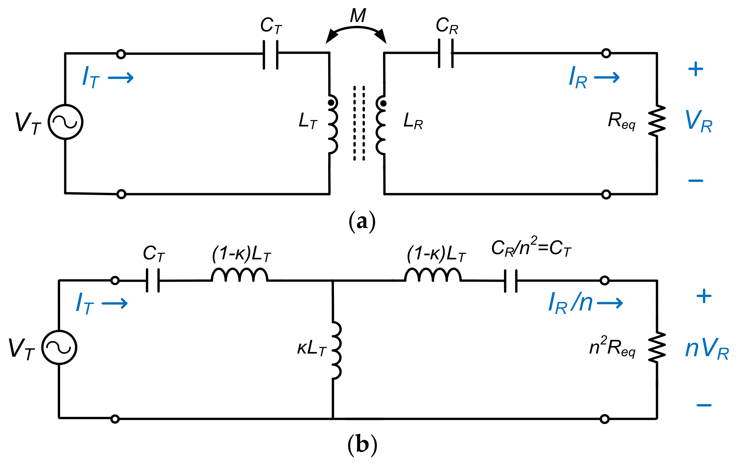
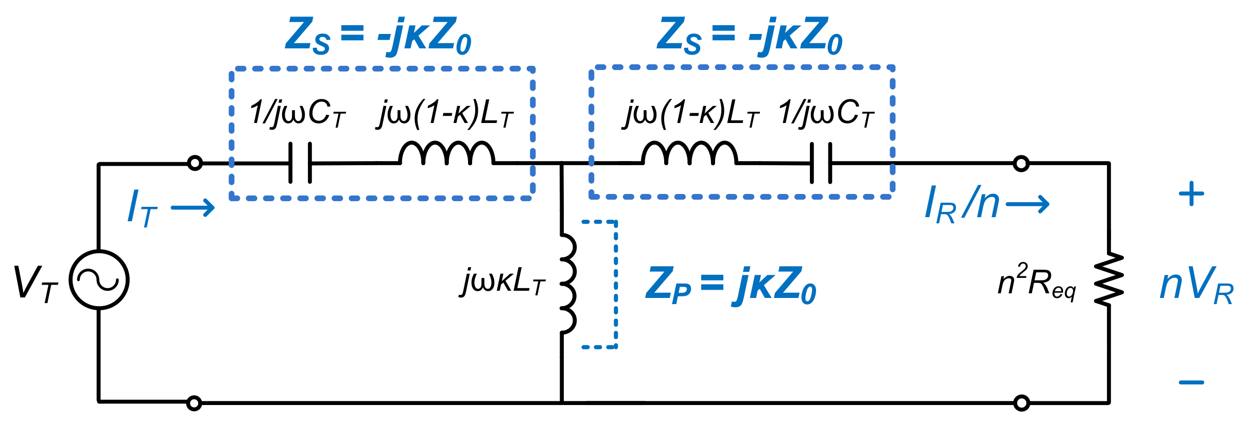
2. Current Source Characteristic of Series-Series Compensated Wireless Power Transfer

In the proposed wireless battery charging system, the SS-WPT system followed by AC-DC converter consists of a half-bridge inverter, resonant tank, full-bridge rectifier, filter, and load as the battery, as shown in Figure 3. The half-bridge inverter applies a square voltage into the resonant tank. The square voltage, Vsquare can be described as:
V s q u a r e ( t ) = { V I N 0 ( 0 < ω t π ) ( π < ω t 2 π )
where ω = 2 π f S and f S is the switching frequency of the half-bridge inverter in Figure 3.
The resonant tank consists of s transmitter coil, receiver coil, transmitter capacitor, and receiver capacitor. The capacitors in the resonant tank resonate with coils and improve the conversion efficiency of the system. Since the capacitors are in series with coils, the structure is called series-series (SS) compensation [19,20]. Since the series-series compensated resonant tank acts as a band pass filter, the effect of any harmonic components in the input square voltage Vsquare can be neglected, except for its fundamental component. Then, the transmitter and receiver voltages in the resonant tank are sinusoidal and expressed as VT and VR, respectively. The transmitter and receiver currents are also sinusoidal and expressed as IT and IR, respectively. The load represented as RL can be described with an equivalent load resistance Req [20]:
R e q = 8 π 2 R L
Figure 4a shows the equivalent circuit of the SS-WPT system in Figure 3, which consists of a sinusoidal transmitter voltage VT, capacitors, a coupled-inductor model, and an equivalent load resistance Req. The components in the receiver side can be transformed into the transmitter side by the effective transformer turns-ratio, n. Here, the term n can be expressed as:
n = L T / L R
where LT and LR are the transmitter coil’s self-inductance and receiver coil’s self-inductance, respectively.
The modified equivalent circuit of SS-WPT system can be represented with coupling coefficient κ, LT, and CT as shown in Figure 4b, assuming n = 1 and CT = CR. Figure 5 shows the modified equivalent circuit of SS-WPT system in frequency-domain.
The series impedance ZS and parallel impedance ZP are expressed as:
Z S = j ω L T ( 1 ω 2 ω r 2 ) j κ ω L T = j κ ω r L T = j κ Z O   and
Z P = j κ ω L T = j κ ω r L T = j κ Z O
where ωr is the resonant angular frequency and ZO is the characteristic impedance. The series impedance ZS and parallel impedance ZP have the same magnitude, but different phase. To define the characteristics between input and output parameters, the resonant tank can be described as the transmission matrix in Equation (6). From Equation (6), the relationship between input and output parameters can be obtained in as Equation (7):
[ V T I T ] = [ 0 j κ Z O j 1 κ Z O 0 ] [ n V R I R / n ]
V T = j κ Z O I R / n   and   I T = j κ 1 Z O n V R
In Equation (7), it is known that the sinusoidal receiver current IR is proportional to the sinusoidal transmitter voltage VT. This means that SS-WPT system driven by the fixed output voltage of AC-DC converter behaves as a constant current-source. In addition, if the magnitude of the output voltage of AC-DC converter is controlled, the SS-WPT system is able to be a voltage controlled current-source at the resonant frequency. From Equation (7), the battery charging current, Ich of the SS-WPT system in Figure 3 can be described with the input voltage VIN as follows:
I c h = 4 π 2 · n V I N κ Z O
Then, the output voltage VO can be expressed with the Ich as in Equation (9):
V O = I c h R L = 4 π 2 · n V I N κ Z O R L
Since the output voltage VO of SS-WPT system is clamped at the battery voltage Vbat, the load resistance RL can be determined from the Vbat and Ich:
R L = V b a t I c h

3. Implementation of CC-CV and MCC Charging

When the battery is not charged, it can be approximately modeled as only a capacitor with a high capacitance. At this state, the battery voltage Vbat is called open circuit voltage VOC. On the other hand, when the battery is charged by the charging current Ich, the battery voltage Vbat is called closed circuit voltage VCC, which is lower than VOC due to the IR voltage drop Vη across the overpotential resistance Rη and the voltage drop VP by polarization. The relationship between VOC and VCC can be expressed as:
V C C = V O C + V η + V P
In order to charge the battery fully, the open circuit voltage VOC should be able to arrive at the maximum allowable battery voltage Vmax_bat. However, although the VCC observed externally while being charged can reach to the Vmax_bat, the VOC is always lower than the Vmax_bat due to the two voltage drops in Equation (11). To solve this, the charging current Ich should be reduced to a predetermined small value Ism at the end-of-charge because the Vη and VP are proportional to the Ich.

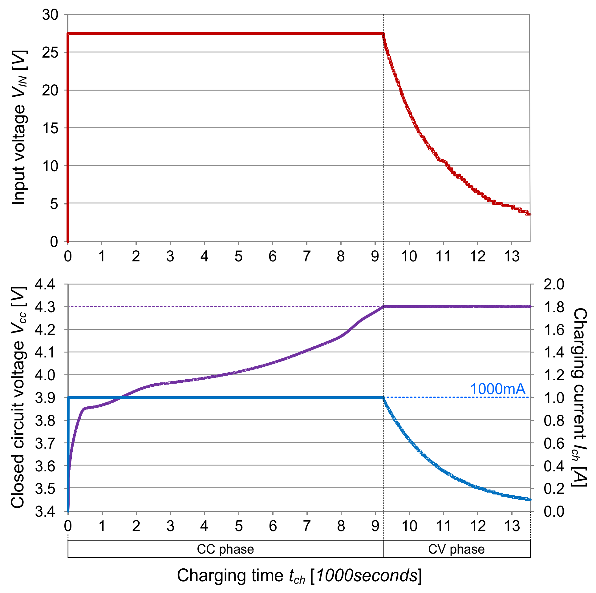
3.1. CC-CV Charging Profile

Figure 6a shows the concept on implementation of constant-current and constant-voltage charging in the proposed system. On the CC phase of the CC-CV charging, the relative high current is required for Ich for the fast charge. Since the charging current Ich of SS-WPT system is proportional to the input voltage VIN as in Equation (8), this means that the output voltage of AC-DC converter in the proposed wireless charging system (or VIN) must be set high. According to this principle, a fixed high VIN is required for a constant high Ich in the proposed system and then, the Ich will charge the battery directly until the closed circuit voltage VCC reaches the maximum allowable battery voltage Vmax_bat, as shown in Figure 6a.
On the CV phase, the Ich begins to decreasing and the decreasing Ich reduces the two voltage drops of Vη and VP to allow the open circuit voltage VOC to reach the maximum allowable battery voltage Vmax_bat. At the end of CV phase, the Ich reaches the predetermined small current Ism. For this mechanism, the proposed system must reduce the output voltage of AC-DC converter on CV phase. As a result, the Ich of SS-WPT system will decrease and the open circuit voltage VOC will continue to increase. The two voltage drops Vη and VP will decrease gradually on the CV phase. On the other hand, the closed circuit voltage VOC will be hold at the maximum allowable battery voltage Vmax_bat due to the constant sum of the increased open circuit voltage VOC and the decreased two voltage drops Vη and VP.
When CC-CV charging is implemented in the conventional system, any transient phase may occur during the switching time from CC control mode to CV control mode [7]. However, in the proposed wireless battery charging system, the current source characteristic of SS-WPT system is used on the CC phase and only the voltage feedback loop is required on the CV phase. This means that in the proposed system, the CC phase is always switched into the CV phase smoothly.

3.2. MCC Charging Profile

Figure 6b shows the concept on implementation of multi-current charging in the proposed system. The MCC charging is composed of various CC phases with different constant magnitudes for Ich. In this profile, whenever the closed circuit voltage VCC reaches the predetermined voltage Vpre_bat, the charging currents Ich is steped down in turn. On the last CC phase of the MCC charging, the Ich should be stepped down to the predetermined small current Ism to charge the battery fully, as shown in Figure 6b. In the proposed wireless battery charging system, this mechanism can be implemented by stepping down the output voltage of AC-DC converter in turn according to the MCC charging profile.

3.3. Other Charging Profile

The battery is charged generally from one current source, and the battery charging circuit carries out the role of the current source in the conventional wireless charging system. On the other hand, the SS-WPT system is used as a current source for the battery charging in the proposed wireless charging system. The current-level of the current source by the SS-WPT can be adjusted variously by changing the output voltage of AC-DC converter, as analyzed in Equation (8). From this, it is noted that most other charging techniques such as constant power charging [21,22,23,24], boost charging [25], varying current decay [26], and optimal charging based on temperature rise and charge time [27] can be implemented easily by the use of the proposed system.

4. Experimental Verification

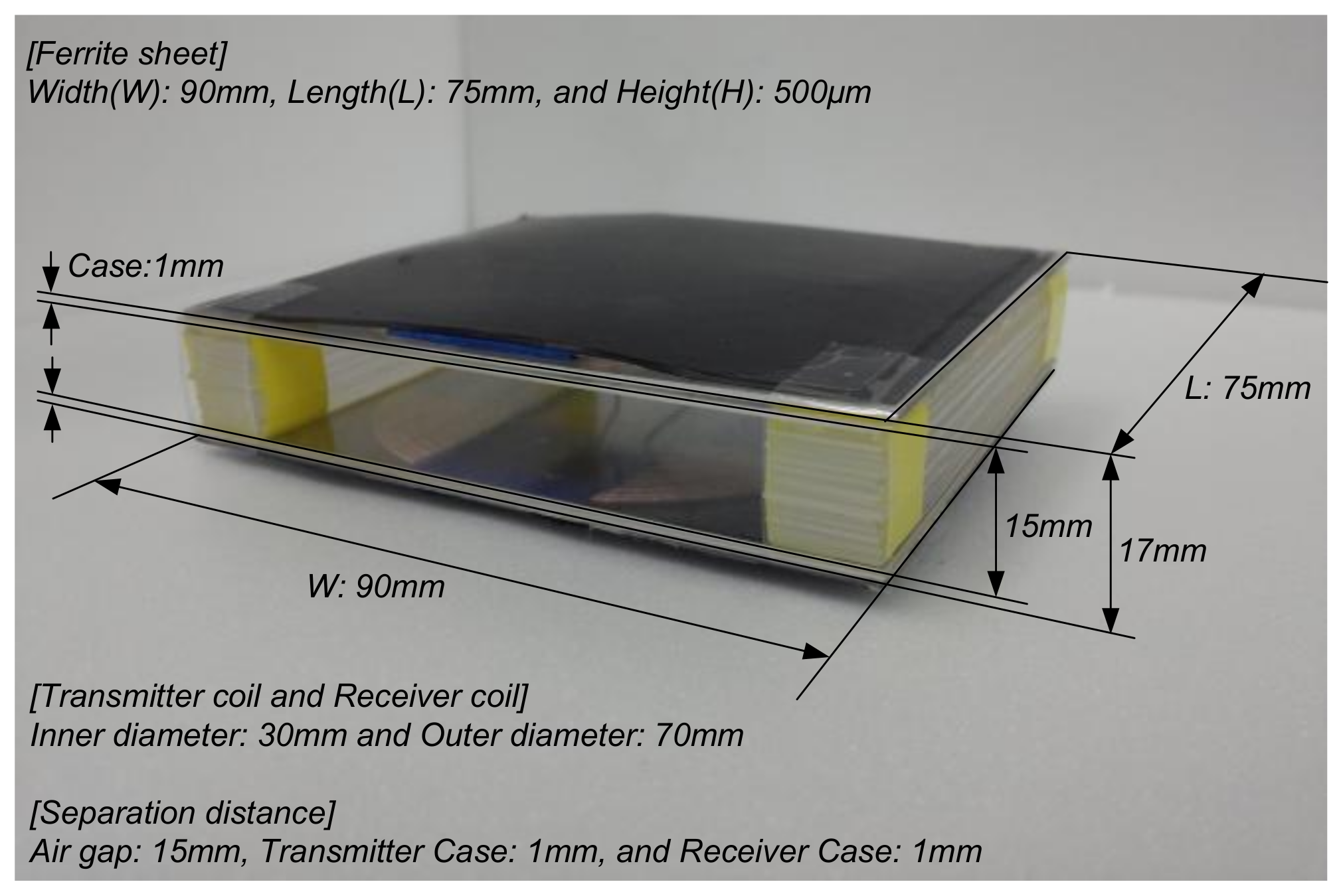
4.1. Experimental Conditions

A prototype was made to verify the proposed wireless battery charging system. Symmetric wire-wound spiral coils (inner diameter: 30 mm and outer diameter: 70 mm) with ferrite sheet (width: 90 mm, length: 75 mm, and height: 500 μm) are fabricated as illustrated in Figure 7. Symmetric wire-wound spiral coils are separated by the air gap of 15 mm. The thickness of transmitter case is 1 mm, and the thickness of receiver case is 1 mm. The parameters in Figure 3 for the experiment are listed in Table 1.
The lithium-ion batteries used for the experiment are prismatic 3100 mAh batteries (Samsung, city, country) which have the minimum allowable battery voltage Vmin_bat of 3.4 V and a maximum allowable battery voltage Vmax_bat of 4.3 V. One battery is charged according to the CC-CV charging profile, and another battery is charged based on the MCC charging profile. The input voltage VIN, the charging current Ich, and the closed circuit voltage VCC are simultaneously recorded by a MV1000 digital recorder (Yokogawa, Japan).
Figure 8 shows the measured Ich by changing the input voltage VIN of SS-WPT system. As shown in Figure 8, the charging current Ich of the proposed system increases linearly from 100 mA to 1000 mA when adjusting the VIN from 3.61 V to 27.46 V. From this result, it is confirmed that the SS-WPT system behaves as a voltage controlled current source at the resonant frequency. The voltage controlled current source will charge the two batteries from the minimum allowable battery voltage Vmin_bat of 3.4 V to the maximum allowable battery voltage Vmax_bat of 4.3 V. And the Ich at the end of CV phase is set to the predetermined small current Ism of 100 mA.

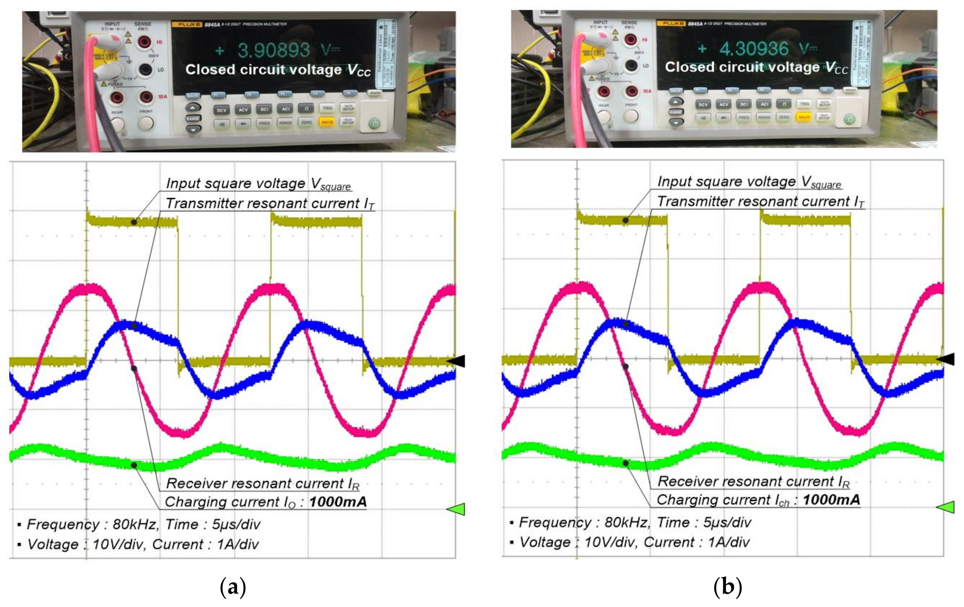
4.2. CC and CV Charging Profile

Figure 9 shows the measured curves of CC-CV charging in the proposed system. The input voltage VIN is set at 27.46 V to obtain the charging current Ich of 1000 mA on the CC phase. Then, the Ich of 1000 mA starts to charge the battery. The closed circuit voltage VCC increases sharply due to the two voltage drops of Vη and VP at the start point of the CC phase, and then reaches the maximum allowable battery voltage Vmax_bat of 4.3 V from 3.9 V, as shown in Figure 9. Figure 10 shows the measured key waveforms in the SS-WPT system while the closed circuit voltage VCC moves from 3.9 V to 4.3 V. As shown in Figure 10, the key waveforms at the VCC of 3.9 V is nearly similar to that at 4.3 V. At the end of CC phase, the VCC reaches the Vmax_bat of 4.3 V, but the open circuit voltage VOC will be not 4.3 V due to the two voltage drops Vη and VP.
On the CV phase after the CC phase, the Ich is decreased by reducing the VIN in order to charge the battery fully. Then, the two voltage drops of Vη and VP is reduced and the open circuit voltage VOC of the battery will arrives at the Vmax_bat of 4.3 V. Figure 11 shows the key waveforms in SS-WPT system on the CV phase. Since the WPT system operates at the resonant frequency, the input square voltage Vsquare and the transmitter resonant current IT are almost in phase. Also, the receiver resonant current IR leads the IT by about π/2. When the Ich reaches the predetermined small current Ism of 100 mA, the CC-CV charging profile ends. The total charging time tch is 13,540 s.
Concretely, the charging times on the CC phase is 9238 s and the CV phase needs a time of 4302 s. With this experiment, it is also confirmed that the total charging time tch measured in the proposed wireless battery charging system is almost equal to that of the conventional wired battery charging system (13,200 s) under the same conditions.

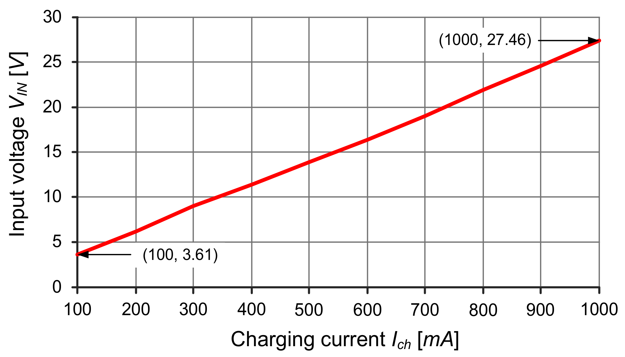
4.3. MCC Charging Profile

Another battery is charged according to the MCC charging profile consisting of four CC phases. Figure 12 shows the measured curves of MCC charging in the proposed system. While charging the battery, the constant charging current Ich is stepped down as follows: CC1 phase (1000 mA)–CC2 phase (800 mA)–CC3 phase (600 mA)–CC4 phase (400 mA)–CC5 phase (100 mA), as shown in Figure 12. The Ich on the last CC phase is set to the predetermined small current Ism of 100 mA to charge the battery fully. The output voltage of AC-DC converter is stepped down to 27.46 V, 22.06 V, 16.38 V, 11.39 V, and 3.61 V in sequence in order to obtain the constant Ich of 1000 mA, 800 mA, 600 mA, 400 mA, and 100 mA, respectively.
The maximum allowable battery voltage Vmax_bat is selected as the predetermined battery voltage Vpre_bat. As a result, when the closed circuit voltage VCC reaches the Vmax_bat of 4.3 V, the Ich are stepped down as shown in Figure 12. The total charging time tch under this MCC charging condition is 16,892 s.

5. Conclusions

This paper proposes a direct wireless battery charging system. Since the proposed system takes advantage of the inherent current-source characteristic of SS-WPT system, the regulation and battery-charging circuits in the conventional system are eliminated and hence it can be easily implemented in many battery applications such as portable electronic devices and electric vehicles, etc. In addition, a voltage controlled current source implemented by changing the output voltage of AC-DC converter in the proposed system can directly charge the battery. This enables us to easily implement various battery charging profiles such as CC-CV, MCC, etc. without an exclusive current feedback loop. In this paper, the abovementioned merits of the proposed system were analyzed in detail and the feasibility was verified with experiments based on a prototype of the proposed system, using Samsung prismatic 3100 mAh lithium-ion batteries, and a CC-CV charging profile. From the results, it can be stated that the proposed system will be more competitive than the conventional system.

Acknowledgments

This work was supported by “Human Resources Program in Energy Technology” of the Korea Institute of Energy Technology Evaluation and Planning (KETEP), granted financial resource from the Ministry of Trade, Industry & Energy, Republic of Korea. (No. 20174030201790). This research was supported by Basic Science Research Program through the National Research Foundation of Korea (NRF) funded by the Ministry of Science, ICT & Future Planning (2015R1C1A1A01051992).

Author Contributions

Il-Oun Lee and Shin-Young Cho were the main researchers who initiated and organized research reported in the paper, all authors including Woo-Seok Lee were responsible for making the prototype of the proposed system and carrying out the experiment.

Conflicts of Interest

The authors declare not conflict of interest.

References

  1. Jiang, H.; Brazis, P.; Tabaddor, M.; Bablo, J. Safety considerations of wireless charger for electric vehicles—A review paper. In Proceedings of the 2012 IEEE Symposium on Product Compliance Engineering Proceedings, Portland, OR, USA, 5–7 November 2012. [Google Scholar]
  2. Why Not A Wire? The Case for Wireless Power, Texas Instruments. Available online: http://www.wirelesspowerconsortium.com/technology/why-not-a-wire-the-case-for-wireless-power.html (accessed on 28 March 2018).
  3. Texas Instruments (TI), “bq51050B and bq51051B Datasheet”. Available online: http://www.ti.com/lit/ds/symlink/bq51050b.pdf (accessed on 28 March 2018).Linear Technology, “LTC4120 Datasheet”. Available online: http://cds.linear.com/docs/en/datasheet/4120fa.pdf (accessed on 28 March 2018).
  4. Li, P.; Bashirullah, R. A Wireless Power Interface for Rechargeable Battery Operated Medical Implants. IEEE Trans. Circuits Syst. II 2007, 54, 912–916. [Google Scholar] [CrossRef]
  5. Dearborn, S. Charging Li-ion batteries for maximum run times. Power Electron. Technol. 2005, 40–49. Available online: www.powerlectronics.com (accessed on 28 March 2018).
  6. Chen, M.; Rincón-Mora, G.A. Accurate, Compact, and Power-Efficient Li-Ion Battery Charger Circuit. IEEE Trans. Circuits Syst. II 2006, 53, 1180–1184. [Google Scholar] [CrossRef]
  7. Lin, C.-H.; Hsieh, C.-Y.; Chen, K.-H. A Li-Ion Battery Charger with Smooth Control Circuit and Built-In Resistance Compensator for Achieving Stable and Fast Charging. IEEE Trans. Circuits Syst. I Regul. Pap. 2010, 57, 506–517. [Google Scholar]
  8. Bruno, D.V.; Wentz, C.T.; Sarpeshkar, R. An Area and Power-Efficient Analog Li-Ion Battery Charger Circuit. IEEE Trans. Biomed. Circuits Syst. 2011, 5, 131–137. [Google Scholar]
  9. Inoa, E.; Wang, J. PHEV Charging Strategies for Maximized Energy Saving. IEEE Trans. Veh. Technol. 2011, 60, 2978–2986. [Google Scholar] [CrossRef]
  10. Chen, B.-Y.; Lai, Y.-S. New digital-controlled technique for battery charger with constant current and voltage control without current feedback. IEEE Trans. Ind. Electron. 2012, 59, 1545–1553. [Google Scholar] [CrossRef]
  11. Liu, Y.-H.; Teng, J.-H.; Lin, Y.-C. Search for an optimal rapid charging pattern for lithium-ion batteries using ant colony system algorithm. IEEE Trans. Ind. Electron. 2005, 52, 1328–1336. [Google Scholar] [CrossRef]
  12. Ikeya, T.; Iwasaki, M.; Takagi, S.; Sugii, Y.; Yada, M.; Sakabe, T.; Kousaka, E.; Tsuchiya, H.; Kanetsuki, M.; Nasu, H.; et al. Collaborative investigation on charging electic-vehicle battery systems for night-time load levelling by Japanese electric power companies. J. Power Sources 1997, 69, 103–111. [Google Scholar] [CrossRef]
  13. Ikeyaa, T.; Sawadab, N.; Takagic, S.; Murakamic, J.-I.; Kobayashid, K.; Sakabee, T.; Kousakaf, E.; Yoshiokag, H.; Katoh, S.; Yamashitai, M.; et al. Multi-step constant-current charging method for electric vehicle, valve-regulated, lead/acid batteries during night time for load-levelling. J. Power Sources 1998, 75, 101–107. [Google Scholar] [CrossRef]
  14. Ikeya, T.; Sawada, N.; Takagi, S.; Murakami, J.-I.; Kobayashi, K.; Sakabe, T.; Kousaka, E.; Yoshioka, H.; Kato, S.; Yamashita, M.; et al. Charging operation with high energy efficiency for electric vehicle valve-regulated lead–acid battery system. J. Power Sources 2000, 91, 130–136. [Google Scholar] [CrossRef]
  15. Ikeya, T.; Sawada, N.; Murakami, J.-I.; Kobayashi, K.; Hattori, M.; Murotani, N.; Ujiie, S.; Kajiyama, K.; Nasu, H.; Narisoko, H.; et al. Multi-step constant-current charging method for an electric vehicle nickel/metal hydride battery with high-energy efficiency and long cycle life. J. Power Sources 2002, 105, 6–12. [Google Scholar] [CrossRef]
  16. Liu, Y.-H.; Hsieh, C.-H.; Luo, Y.-F. Search for an Optimal Five-Step Charging Pattern for Li-Ion Batteries Using Consecutive Orthogonal Arrays. IEEE Trans. Energy Convers. 2011, 26, 654–661. [Google Scholar] [CrossRef]
  17. Liu, Y.-H.; Luo, Y.-F. Search for an Optimal Rapid-Charging Pattern for Li-Ion Batteries Using the Taguchi Approach. IEEE Trans. Ind. Electron. 2010, 57, 3963–3971. [Google Scholar] [CrossRef]
  18. Wang, C.-S.; Covic, G.A.; Stielau, O.H. Power transfer capability and bifurcation phenomena of loosely coupled inductive power transfer systems. IEEE Trans. Ind. Electron. 2004, 51, 148–157. [Google Scholar] [CrossRef]
  19. Moradewicz, A.J.; Kazmierkowski, M.P. Contactless energy transfer system with FPGA-controlled resonant converter. IEEE Trans. Ind. Electron. 2010, 57, 3181–3190. [Google Scholar] [CrossRef]
  20. Steigerwald, L. A comparison of Half-Bridge Resonant Converters. IEEE Trans. Power Electron. 1988, 3, 174–182. [Google Scholar] [CrossRef]
  21. Poon, N.K.; Pong, B.M.H.; Tse, C.K. A constant-power battery charger with inherent soft switching and power factor correction. IEEE Trans. Power Electron. 2003, 18, 1262–1269. [Google Scholar] [CrossRef] [Green Version]
  22. Yan, X.; Patterson, D. A high-efficiency on-board battery charger with unity input power factor. Int. J. Renew. Energy Eng. 2000, 2, 141–147. [Google Scholar]
  23. Kuperman, A.; Levy, U.; Goren, J.; Zafransky, A.; Savernin, A. Battery Charger for Electric Vehicle Traction Battery Switch Station. IEEE Trans. Ind. Electron. 2013, 60, 5391–5399. [Google Scholar] [CrossRef]
  24. Notten, P.H.L.; Veld, J.H.G.; van Beek, J.R.G. Boost charging Li-ion batteries: A challenging new charging concept. J. Power Sources 2005, 145, 89–94. [Google Scholar] [CrossRef]
  25. Chung, S.K.; Andriiko, A.A.; Mon’ko, A.P.; Lee, S.H. On charge conditions for Li-ion and other secondary lithium batteries with solid intercalation electrodes. J. Power Sources 1999, 79, 205–211. [Google Scholar] [CrossRef]
  26. Sikha, G.; Ramadass, P.; Haran, B.S.; White, R.E.; Popov, B.N. Comparison of the capacity fade of Sony US 18650 cells charged with different protocols. J. Power Sources 2003, 122, 67–76. [Google Scholar] [CrossRef]
  27. Zhang, C.; Jiang, J.; Gao, Y.; Zhang, W.; Liu, Q.; Hu, X. Charging optimization in lithium-ion batteries based on temperature rise and charge time. Appl. Energy 2017, 194, 569–577. [Google Scholar] [CrossRef]
Figure 1. Conventional wireless battery charging system.
Energies 11 00791 g001
Figure 2. Proposed wireless battery charging system.
Energies 11 00791 g002
Figure 3. Series-series compensated wireless power transfer circuit in the proposed system.
Energies 11 00791 g003
Figure 4. Equivalent circuits of series-series compensated wireless power transfer system: (a) equivalent circuit and (b) modified equivalent circuit.
Energies 11 00791 g004
Figure 5. Equivalent circuit of series-series compensated wireless power transfer system in frequency domain.
Energies 11 00791 g005
Figure 6. Concept on implementation of (a) constant-current and constant-voltage charging and (b) four-step CC charging with step-down charging current (when the predetermined battery voltage is the maximum allowable battery voltage) profiles in the proposed system.
Energies 11 00791 g006
Figure 7. Symmetric wire-wound spiral coils with ferrite sheet.
Energies 11 00791 g007
Figure 8. Measured relationship between input voltage and charging current in series-series compensated wireless power transfer system.
Energies 11 00791 g008
Figure 9. Measured curves of CC-CV charging in the proposed wireless battery charging method.
Energies 11 00791 g009
Figure 10. Key waveforms of series-series compensated wireless power transfer system in constant-current phase: (a) closed circuit voltage of 3.9 V and load resistance 3.9 Ω at the middle of constant-current phase and (b) closed circuit voltage of 4.3 V and load resistance 4.3 Ω at the end of constant-current phase.
Energies 11 00791 g010
Figure 11. Key waveforms of series-series compensated wireless power transfer system in constant-voltage phase: (a) charging current of 900 mA, (b) charging current of 700 mA, (c) charging current of 500 mA, (d) charging current of 300 mA, and (e) charging current of 100 mA.
Energies 11 00791 g011
Figure 12. Measured curves of MCC charging in the proposed wireless battery charging method.
Energies 11 00791 g012
Table 1. Parameters for experiments.
SymbolDescriptionValues/Part Name
LTSelf-inductance of transmitter coil 50 μH
LRSelf-inductance of receiver coil50 μH
κCoupling coefficient0.4
nTurns-ratio1 (27:27)
CTTransmitter capacitance78 nF
CRReceiver capacitance78 nF
Q1, Q2Switches50CN10N
D1D4DiodesPMEG4030ER
frResonant frequency80 kHz

