1. Introduction
Significantly increasing the proportion of renewable energy in energy production and consumption is an important measure to solve the problems of energy crisis and environmental pollution. At present, there are two main methods for the development and utilization of renewable energy, which are namely “large-scale centralized installation with medium/high voltage integration over long transmission distance for remote consumption” and “scale decentralized installation with low voltage integration for local consumption” [
1].
Using micro-grids is an effective way to consume renewable energy locally [
2]. A micro-grid can be classified as an AC micro-grid or DC micro-grid, depending on the properties of the common bus to which the devices are connected to for the exchange of power. In the DC micro-grid, it is easy to coordinate the operation of devices, because the voltage of DC bus is the only measurement for control, with no frequency or reactive power problems found to exist as in the AC system. Furthermore, the voltage disturbance from the AC side can be effectively isolated to ensure high reliability of the DC system power supply. With an increase in the DC equipment in the micro-grid, the development of the DC micro-grid has attracted more interest [
3,
4,
5,
6].
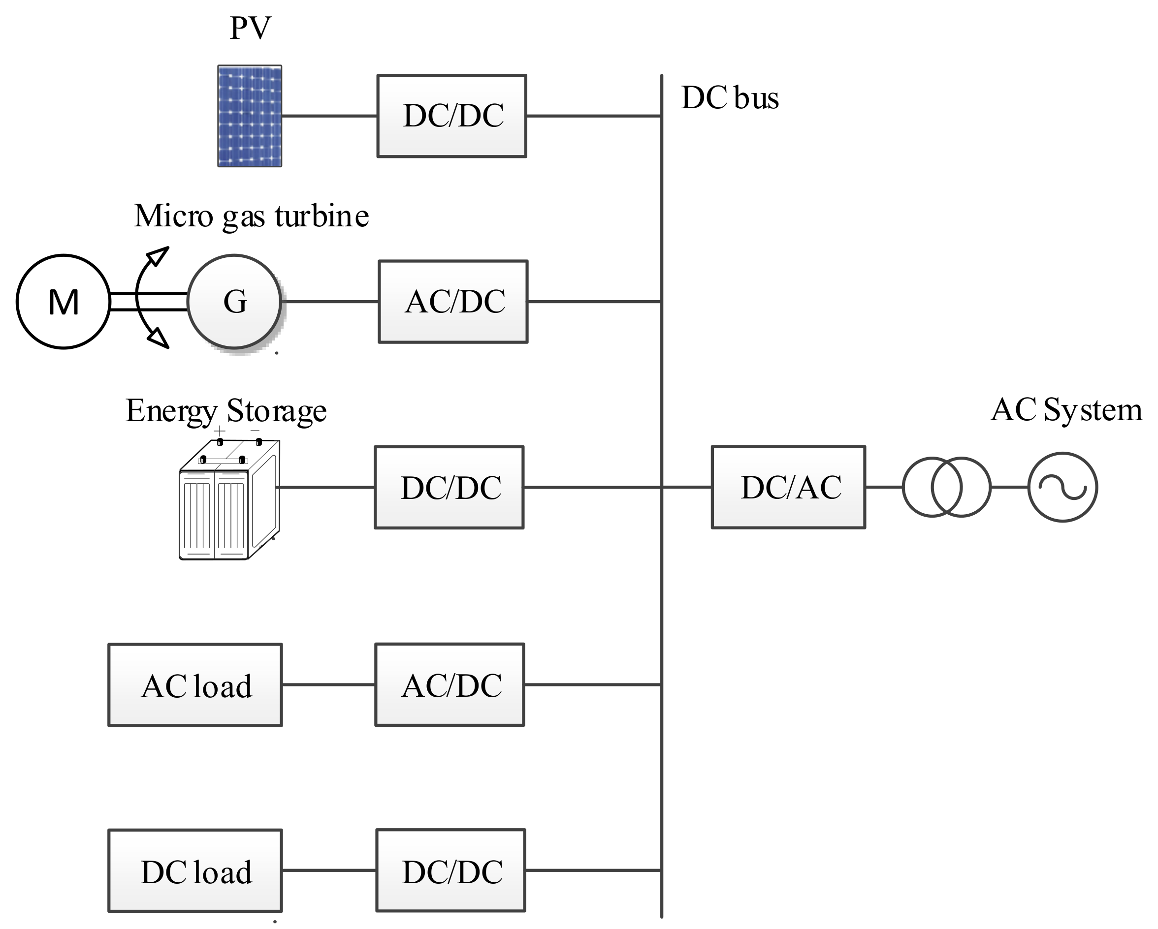
Figure 1 shows a typical grid-connected DC micro-grid, including the photovoltaic generation unit, DC load, AC load, energy storage unit, grid-connected inverter unit and transmission line.
In order to achieve DC bus voltage stability and power balance in the system of the DC micro-grid, a reliable control strategy is needed for the coordinated operation of multiple devices. Similar to the hierarchical control structure in the AC micro-grid, the control structure in the DC micro-grid can also be divided into three layers from top to bottom, including the distribution network operator (DNO), micro-grid central controller (MCC) and local controller (LC) [
7]. The power grid interacts with the micro-grid through MCC, whose main function is to maximize the benefit of the micro-grid and coordinate the control of LCs.
Master-slave control and peer-to-peer control are two typical control methods in MCC [
8,
9]. In the DC micro-grid, DC bus voltage is an important signal that indicates the stability of the DC system. In master-slave control mode, one power source or energy storage device is selected as the master control unit to control the DC bus voltage and the other devices are slave control units in constant output power mode. As it is responsible for supplementing a power shortage in a system and balancing the power fluctuation generated by renewable energy, the master control unit is required to have large reserve capacity and fast power regulation capability. Master-slave control is one type of centralized control. In this centralized control, a communication system is necessary to designate and switch the master control unit and slave-control units in the micro-grid. However, delay of the communication system usually has an adverse effect on the system.
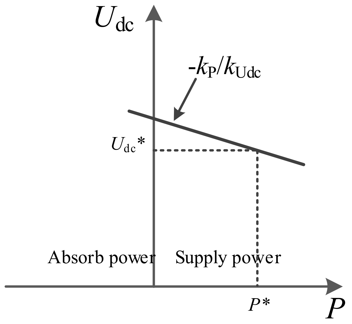
In peer-to-peer control mode, the equipment with power regulation ability (such as power supply, energy storage device, etc.) adopts droop control, whose output power is related to the DC voltage in the micro-grid. When the DC voltage falls (rises), the device with droop control will increase (decrease) its output power or reduce (increase) its absorption power in order to prevent the DC voltage from falling (raising). The peer-to-peer control has high reliability because all the droop-controlled devices are equipotent and are involved in DC bus voltage control and power regulation. When one converter station in the system is out of operation, the power shortage will be shared by all the droop-controlled devices in order to ensure the stability of the DC voltage without overloading any units. However, one shortcoming of droop control is that the variation in DC voltage will cause fluctuations in the device output power, especially in the micro-grid integrated with renewable energies. The output power of renewable energy is greatly influenced by the natural environment. If there is a power fluctuation in the environment, this will cause fluctuation of the DC voltage, thus affecting the output power of other droop-controlled devices. The droop control is not suitable when the output power of device is required to be constant.
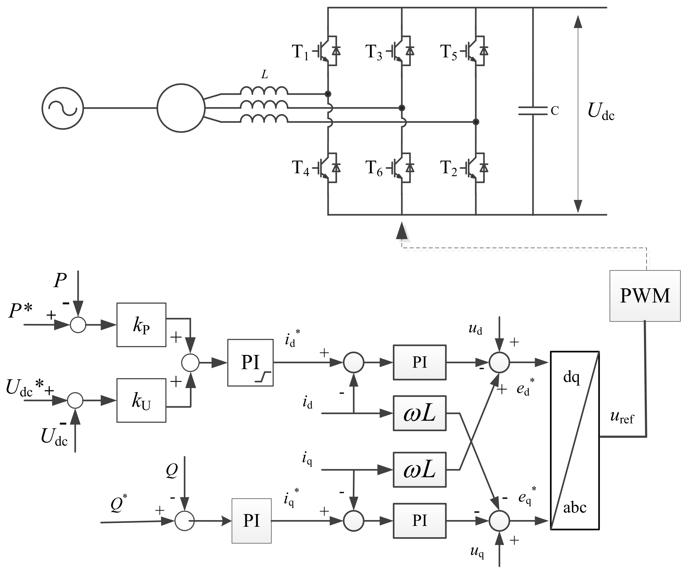
A grid-connected DC micro-grid is linked with the AC power grid through a DC/AC inverter. Obviously, if a constant tie-line power is required, the grid-connected inverter must be under the constant power control mode. Without the help of a communication system, the grid-connected inverter cannot participate in power regulation and distribution automatically when the power imbalance is caused by the outage of equipment in the micro-grid. The grid-connected inverter can adopt droop control to have the ability to provide power support to the micro-grid. However, the tie-line power will be influenced by voltage fluctuation in the DC bus.
At present, there are many ideas for tie-line power control from the perspective of the renewable energy power generation unit, demand of side management and energy storage system. Previous studies [
10,
11,
12,
13] have proposed some methods to suppress the power fluctuation of renewable energy with energy storage devices. From the perspective of the demand of side response, the tie-line power of micro-grid becomes smooth once combined with the energy storage system as shown in a previous study [
14]. Taking reduction in the tie-line power fluctuation as the optimization goal, a previous study [
15] also proposed a micro-grid energy management control strategy. However, most of these methods depend on the communication system to coordinate the operation of devices in a micro-grid, resulting in a high cost and complex control.
In order to solve this problem, an improved droop control strategy is proposed in this paper, which can simplify tie-line power control of a DC micro-grid. With this control strategy, the grid-connected inverter can not only keep the advantages of droop control, such as on the lack of reliance on the communication system and high reliability, but also maintain the advantage of maintaining a constant tie-line power in the steady state that will not be affected by renewable energy fluctuation. Based on the simulation model of the DC micro-grid built in MATLAB/Simulink, the effectiveness of the control strategy is verified. The results show that the control strategy has a good transient and steady performance.
3. Improved Droop Control Strategy for DC Micro-Grid
3.1. Local Level Control
In a system with traditional droop control, the “plug & play” functions of devices can be easily achieved as these devices have equal positions and no master or slave device exists. The bus voltage in the DC micro-grid is co-controlled by multiple power regulating devices, which improves the reliability of the system. The linear relationship between the voltage error and power error in droop control allows the devices to quickly participate in power regulation of micro-grid, but their output power is easily affected by DC bus voltage fluctuations. The stochastic fluctuation of the load and renewable energy in the micro-grid will cause variation in the DC bus voltage, thus affecting the power output of all droop-controlled devices and decreasing their steady-state performance.
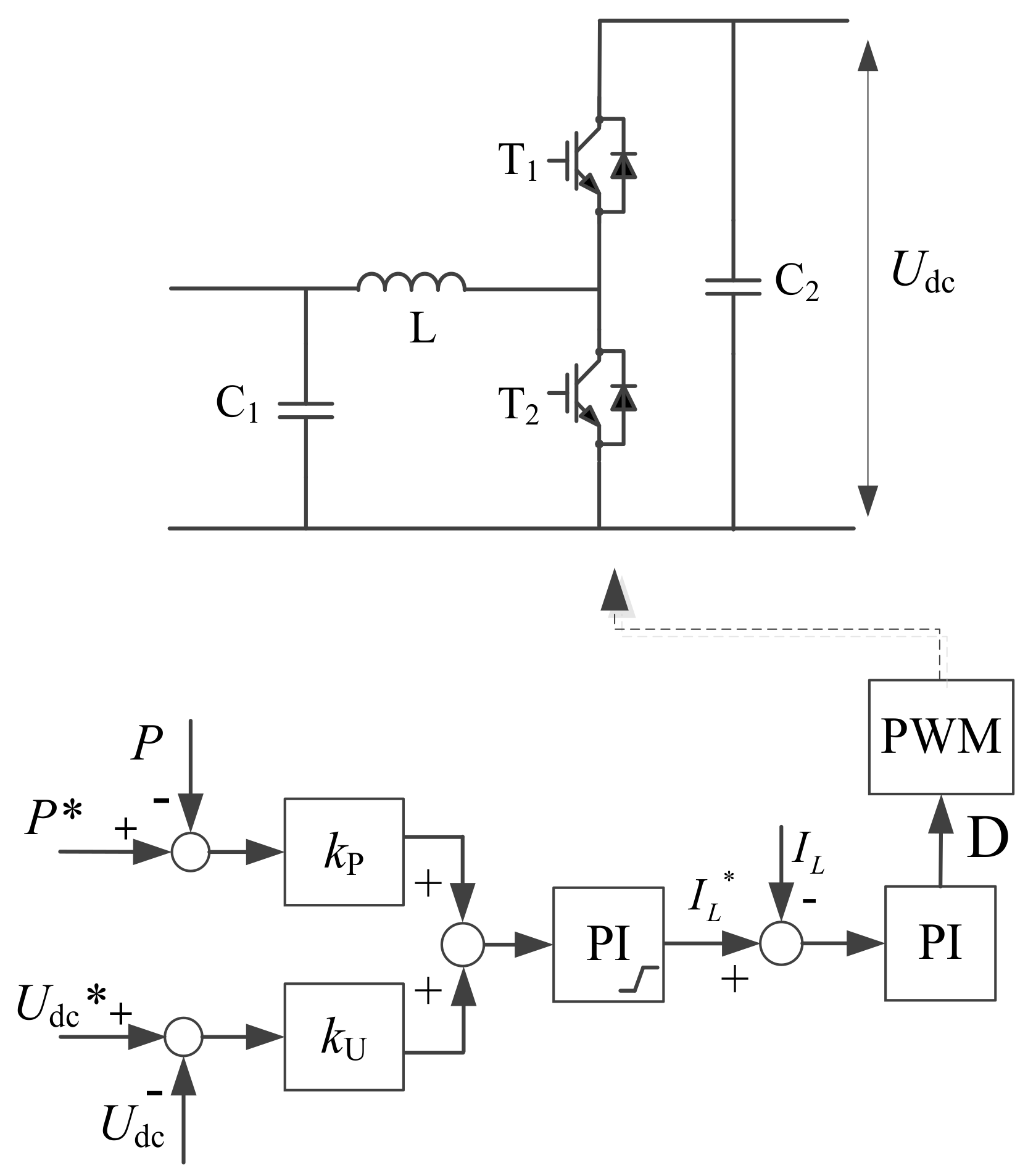
In order to solve the above problems and fully utilize the high reliability of droop control, an improved droop control strategy is proposed here, in which devices are divided into master device and slave devices. On the basis of the traditional droop control, a piecewise droop control is formed by adding a segment of constant voltage to the master device and a segment of constant power to the slave devices, respectively.
3.1.1. Master Device Control
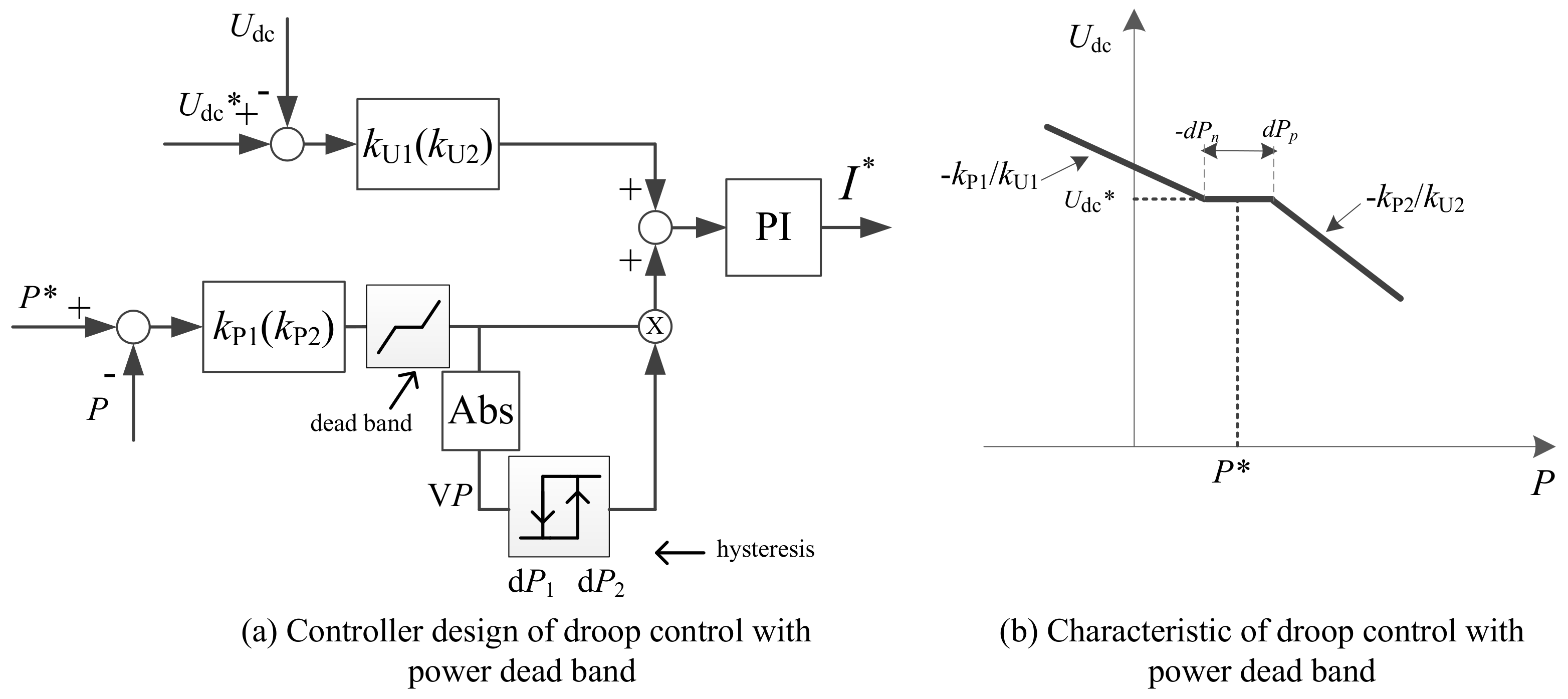
The droop controller design for the master device and its droop characteristics with a constant voltage region are shown in
Figure 6. By adding a dead band to the active power error, the constant voltage control can be achieved.
Considering the influence of the power dead band, the operation range of DC bus voltage and the equipment capacity, droop control can be divided into two sections in terms of droop characteristics with different droop slopes, as shown in Equation (4).
where
Pmax and
Pmin are the maximum and minimum output power of the equipment;
Udc_max and
Udc_min are the maximum and minimum DC voltage of DC micro-grid; and ∆
P is the power dead band value, respectively.
The characteristic of the droop control with the additional power dead band is shown in
Figure 6b. When the output power of renewable energy fluctuates within a certain dead band, the master device can adjust its output power to maintain a constant DC bus voltage. When the power fluctuation range exceeds the dead band, the master device will switch to the droop control section and the DC bus voltage will change. To avoid the jumping between different control mode, a hysteresis is added in the output of the power error. In
Figure 6a, V
P is the absolute value of output of dead band, while d
P1 and d
P2 are the hysteresis values. The hysteresis block the outputs of 1 when V
P increases to be larger than d
P2. The hysteresis block outputs 0 when V
P decreases to be smaller than d
P1.
3.1.2. Slave Device Control
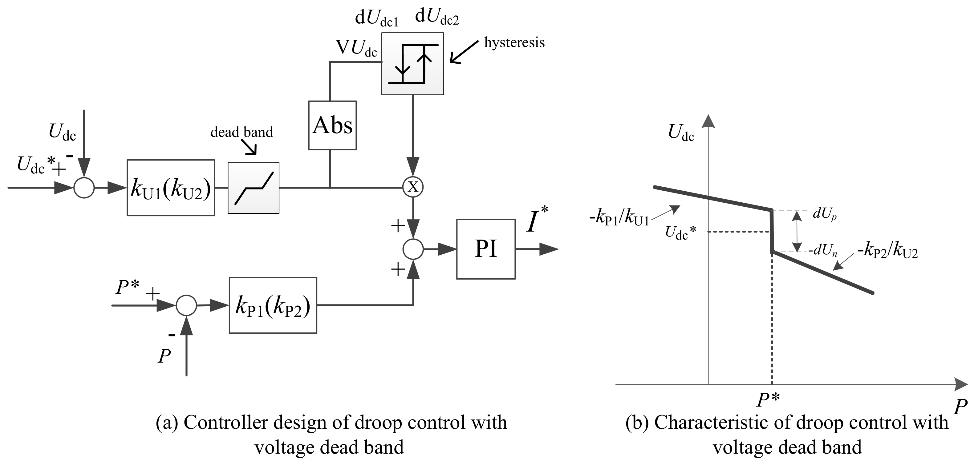
The droop controller design for the slave devices and its droop characteristics with a constant power section are shown in
Figure 7. By adding a dead band to the DC voltage error, the constant power control can be achieved. A hysteresis is added to avoid the jumping between different control modes. In
Figure 6a, V
Udc is the absolute value of output of the dead band, while d
Udc1 and d
Udc2 are the hysteresis values.
Considering the influence of the voltage dead band, droop control characteristics can be divided into two sections with different droop slopes as:
where ∆
U is the saturation value of the voltage dead band.
The droop control with the additional voltage dead band is shown in
Figure 7b. When the DC bus voltage fluctuates within a certain dead band, the slave devices output constant power. When the DC bus voltage fluctuation range exceeds the dead band, the slave devices switch to the droop control section to stabilize the DC voltage by adjusting their output power.
3.2. Micro-Grid Level Control
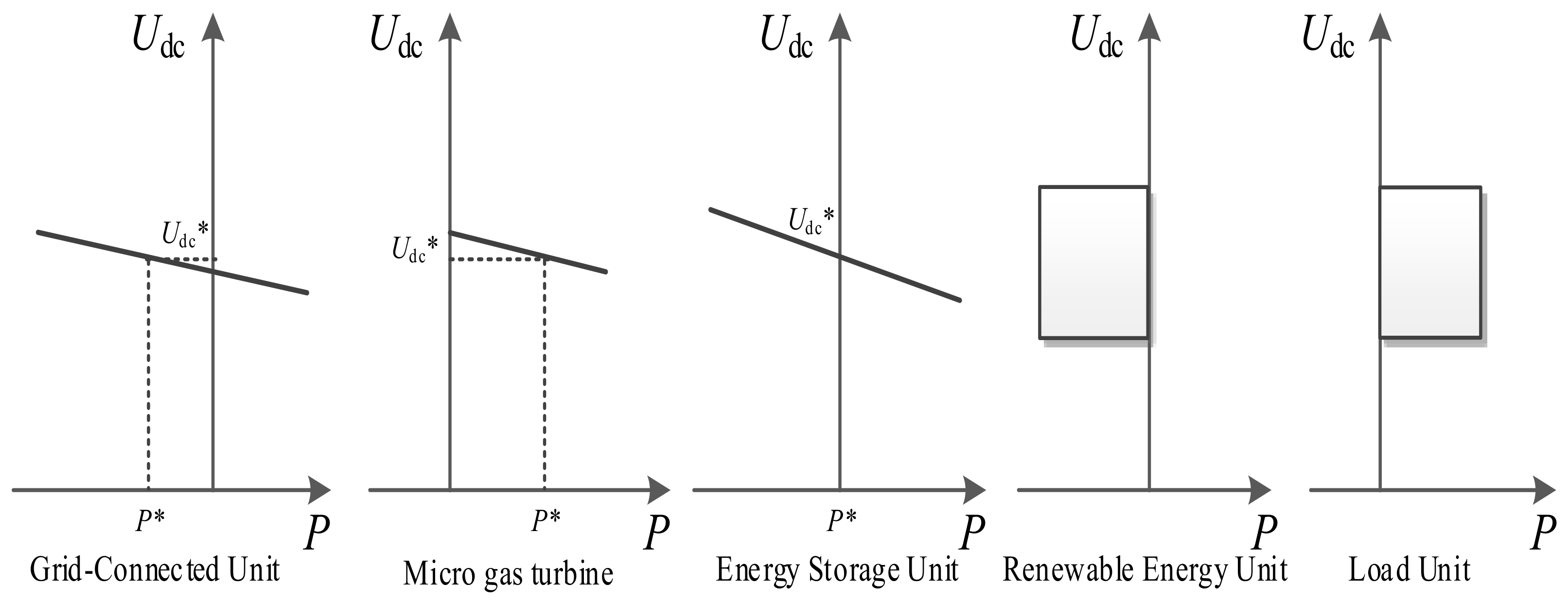
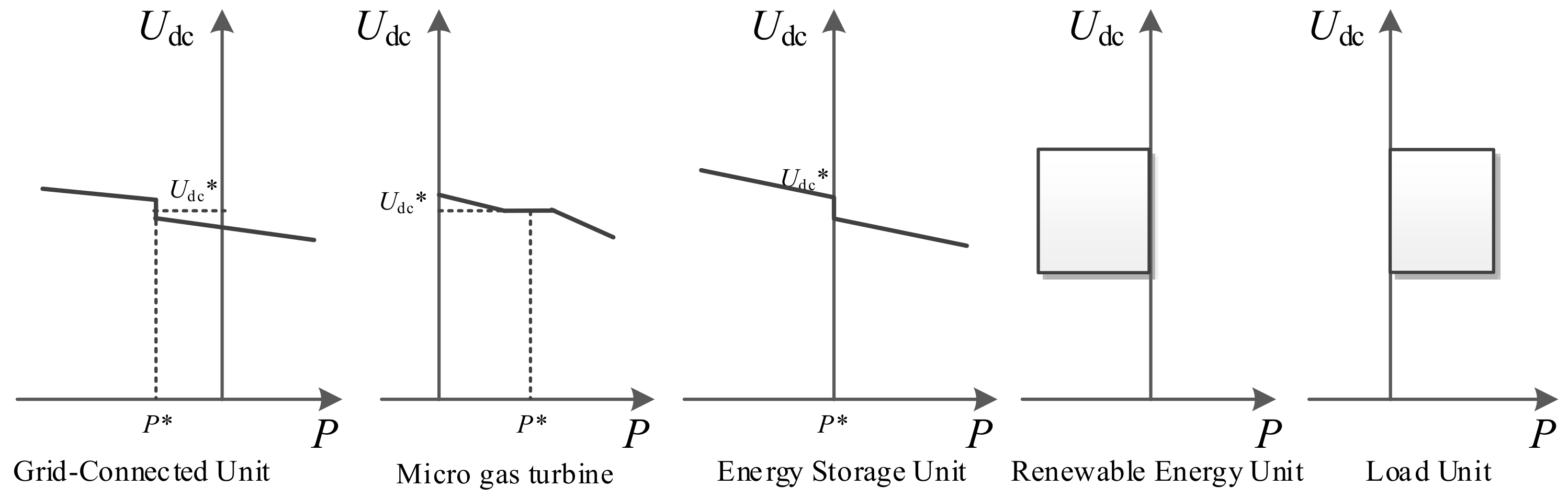
The output characteristics of the equipment in the DC micro-grid with improved coordinated control are shown in
Figure 8. The droop controller can be designed with the following steps. The master control unit should be chosen from the equipment with the ability to regulate power, such as generators and energy storage system. As there is only one master control unit, the other equipment will be slave control units. The power output of each device (i.e., the reference operating point) could also be determined with an optimization calculation in the MCC layer. The slope of droop curve can be calculated according to the capacity of equipment and operation range of DC voltage.
Taking the renewable energy fluctuation into account, the droop slope needs some modification. The power dead band of the master equipment ∆P is determined by the fluctuation range of renewable energy. The determination of the voltage dead band of slave equipment ∆Udc is based on the DC voltage variation range, which could be aided by power flow calculation. After this, the hysteresis value should be determined to avoid jumping of control modes.
In the DC micro-grid, the micro gas turbine usually operates as the master control unit because its output power can be adjusted flexibly and easily as shown in
Figure 1. To maintain constant tie-line power, the grid-connected inverter operates in the slave control mode. Since only one master device with constant DC voltage control is allowed in the DC micro-grid, the other devices with power regulation capability work in slave control mode.
In steady state, the master device is responsible for stabilizing and complementing the power output of renewable energy, and the slave devices output constant power, which is similar to the traditional master-slave control. In the transient state, all the master and slave devices switch to droop control sections to dominate the DC voltage and balance system power in a coordinated manner, which is similar to the traditional droop control.
5. Conclusions
The DC micro-grid requires a coordinated control method to maintain stable operation of distributed energy, energy storage device, energy conversion device and loads in the system. Droop control is usually adopted to improve system reliability. However, the active power of the device is easily affected by the fluctuations in DC voltage, which becomes more prominent when renewable energy is integrated. This paper proposes an improved droop control strategy, which forms a piecewise droop control by adding a power dead band and voltage dead band to the master device and slave devices in DC micro-grid, respectively. In the steady state, the master device stabilizes and complements the power output of renewable energy, while slave devices output constant power, which is similar to the traditional master-slave control. In the transient state, both master and slave devices switch to droop control mode, jointly controlling the DC voltage and balancing system power, which are similar to the traditional droop control. The simulation results indicate that this control strategy shows a good transient and steady performance.


